
HYBRID UML COMPONENTS FOR THE DESIGN OF
COMPLEX SELF-OPTIMIZING MECHATRONIC SYSTEMS
∗
Sven Burmester
†
and Holger Giese
Software Engineering Group, University of Paderborn
Warburger Str. 100, D-33098 Paderborn, Germany
Oliver Oberschelp
Mechatronic Laboratory Paderborn, University of Paderborn
Pohlweg 98, D-33098 Paderborn, Germany
Keywords:
Mechatronic, Self-optimization, Control, Hybrid Systems, Components, Reconfiguration, Unified Modelling
Language (UML), Real-Time
Abstract:
Complex technical systems, such as mechatronic systems, can exploit the computational power available to-
day to achieve an automatic improvement of the technical system performance at run-time by means of self-
optimization. To realize this vision appropriate means for the design of such systems are required. To support
self-optimization it is not enough just to permit to alter some free parameters of the controllers. Furthermore,
support for the modular reconfiguration of the internal structures of the controllers is required. Thereby it
makes sense to find a representation for reconfigurable systems which includes classical, non-reconfigurable
block diagrams. We therefore propose hybrid components and a related hybrid Statechart extension for the
Unified Modeling Language (UML); it is to support the design of self-optimizing mechatronic systems by al-
lowing specification of the necessary flexible reconfiguration of the system as well as of its hybrid subsystems
in a modular manner.
1 INTRODUCTION
Mechatronic systems are technical systems whose be-
havior is actively controlled with the help of computer
technology. The design of these systems is marked by
a combination of technologies used in mechanical and
electrical engineering as well as in computer science.
The focus of the development is on the technical sys-
tem whose motion behavior is controlled by software.
The increasing efficiency of microelectronics, par-
ticularly in embedded systems, allows the develop-
ment of mechatronic systems that besides the re-
quired control use computational resources to im-
prove their long term performance. These forms of
self-optimization allow an automatic improvement of
a technical system during operation which increases
the operating efficiency of the system and reduces the
operating costs.
∗
This work was developed in the course of the Spe-
cial Research Initiative 614 - Self-optimizing Concepts and
Structures in Mechanical Engineering - University of Pader-
born, and was published on its behalf and funded by the
Deutsche Forschungsgemeinschaft.
†
Supported by the International Graduate School of Dy-
namic Intelligent Systems. University of Paderborn
A generally accepted definition of the term self-
optimization is difficult to find. In our view, the core
function of self-optimization in technical systems is
generally an automatic improvement of the behavior
of the technical system at run-time with respect to de-
fined target criteria. In a self-optimizing design, de-
velopment decisions are being shifted from the design
phase to the system run-time.
There are two opportunities of optimization during
runtime. The first is to optimize parameters (Li and
Horowitz, 1997) the second is to optimize the struc-
ture. However, alteration of the free parameters of the
system will not lead very far because many charac-
teristics, in particular those of the controller, can be
altered only in the internal structures and not just by
a modification of parameters (F
¨
ollinger et al., 1994;
Isermann et al., 1992).
While most approaches to hybrid modeling (Hen-
zinger et al., 1995; Bender et al., 2002; Alur et al.,
2001) describe how the continuous behavior can be
modified when the discrete control state of the sys-
tem is altered, we need an approach that allows the
continuous behavior as well as its topology to be al-
tered in a modular manner to support the design of
self-optimizing systems.
222
Burmester S., Giese H. and Oberschelp O. (2004).
HYBRID UML COMPONENTS FOR THE DESIGN OF COMPLEX SELF-OPTIMIZING MECHATRONIC SYSTEMS.
In Proceedings of the First International Conference on Informatics in Control, Automation and Robotics, pages 222-229
DOI: 10.5220/0001141502220229
Copyright
c
SciTePress

Our suggestion is to integrate methods used in me-
chanical engineering and software engineering to sup-
port the design of mechatronic systems with self-
optimization. We therefore combine component di-
agrams and state machines as proposed in the forth-
coming UML 2.0 (UML, 2003) with block diagrams
(F
¨
ollinger et al., 1994) usually employed by control
engineers. The proposed component-based approach
thus allows a decoupling of the domains: A control
engineer can develop the continuous controllers as
well as their reconfiguration and switching in form of
hybrid components. A software engineer on the other
hand can integrate these components in his design of
the real-time coordination. As this paper focusses the
modeling aspect we set simulation aside. Simulation
results can be found in (Liu-Henke et al., 2000).
In Section 2 we will examine related work. Section
3 discusses problems resulting from reconfiguration
by means of an application example. In Section 4,
our approach to hybrid modeling with an extension of
UML components and Statecharts will be described.
Thereafter we describe our model’s runtime platform
in Section 5 and sum up in Section 6 with a final con-
clusion and an outlook on future work.
2 RELATED WORK
A couple of modeling languages have been proposed
to support the design of hybrid systems (Alur et al.,
1995; Lamport, 1993; Wieting, 1996). Most of these
approaches provide models, like linear hybrid au-
tomata (Alur et al., 1995), that enable the use of ef-
ficient formal analysis methods, but lack of methods
for structured, modular design, that is indispensable
in a practical application (M
¨
uller and Rake, 1999).
To overcome this limitation, hybrid automata have
been extended to hybrid Statecharts in (Kesten and
Pnueli, 1992). Hybrid Statecharts reduce the visual
complexity of a hybrid automaton through the use of
high-level constructs like hierarchy and parallelism,
but for more complex systems further concepts for
modularization are required.
The hybrid extensions HyROOM (Stauner et al.,
2001), HyCharts (Grosu et al., 1998; Stauner, 2001)
and Hybrid Sequence Charts (Grosu et al., 1999) of
ROOM/UML-RT integrate domain specific model-
ing techniques. The software’s architecture is spec-
ified similar to ROOM/UML-RT and the behavior
is specified by statecharts whose states are asso-
ciated with systems of ordinary differential equa-
tions and differential constraints (HyCharts) or Mat-
lab/Simulink block diagrams (HyROOM). HyROOM
models can be mapped to HyCharts (Stauner et al.,
2001). Through adding tolerances to the continuous
behavior this interesting specification technique en-
ables automatic implementation, but support for the
modular reconfiguration is not given.
In (Conrad et al., 1998) guiding principles for the
design of hybrid systems are sketched. It describes
how to apply techniques that are used in automo-
tive engineering, like the combination of statecharts,
blockdiagrams and commercial tools. Following this
approach hybrid systems need to be decoupled into
discrete and continuous systems in the early design
phases. Therefore a seamless support and a common
model are not provided.
Within the Fresco project the description language
Masaccio (Henzinger, 2000) which permits hierar-
chical, parallelized, and serially composed discrete
and continuous components has been developed. A
Masaccio model can be mapped to a Giotto (Hen-
zinger et al., 2003) model, that contains sufficient in-
formation about tasks, frequencies, etc. to provide an
implementaion. The project provides a seamless sup-
port for modeling, verification and implementation,
but our needs for advanced modeling techniques that
support dynamic reconfiguration are not addressed.
3 MODELING
RECONFIGURATION
We will use the switching between three controller
structures as a running example to outline the result-
ing modeling problems. The concrete example is an
active vehicle suspension system with its controller
which stems from the Neue Bahntechnik Paderborn
3
research project. The project has been initiated and
worked upon by several departments of the Univer-
sity of Paderborn and the Heinz Nixdorf Institute. In
the project, a modular rail system will be developed;
it is to combine modern chassis technology with the
advantages of the Transrapid
4
and the use of existing
rail tracks. The interaction between information tech-
nology and sensor/actuator technology paves the way
for an entirely new type of mechatronic rail system.
The vehicles designed apply the linear drive technol-
ogy used in the Transrapid, but travel on existing rail
tracks. The use of existing rail tracks will eliminate an
essential barrier to the proliferation of new railbound
transport systems (L
¨
uckel et al., 1999).
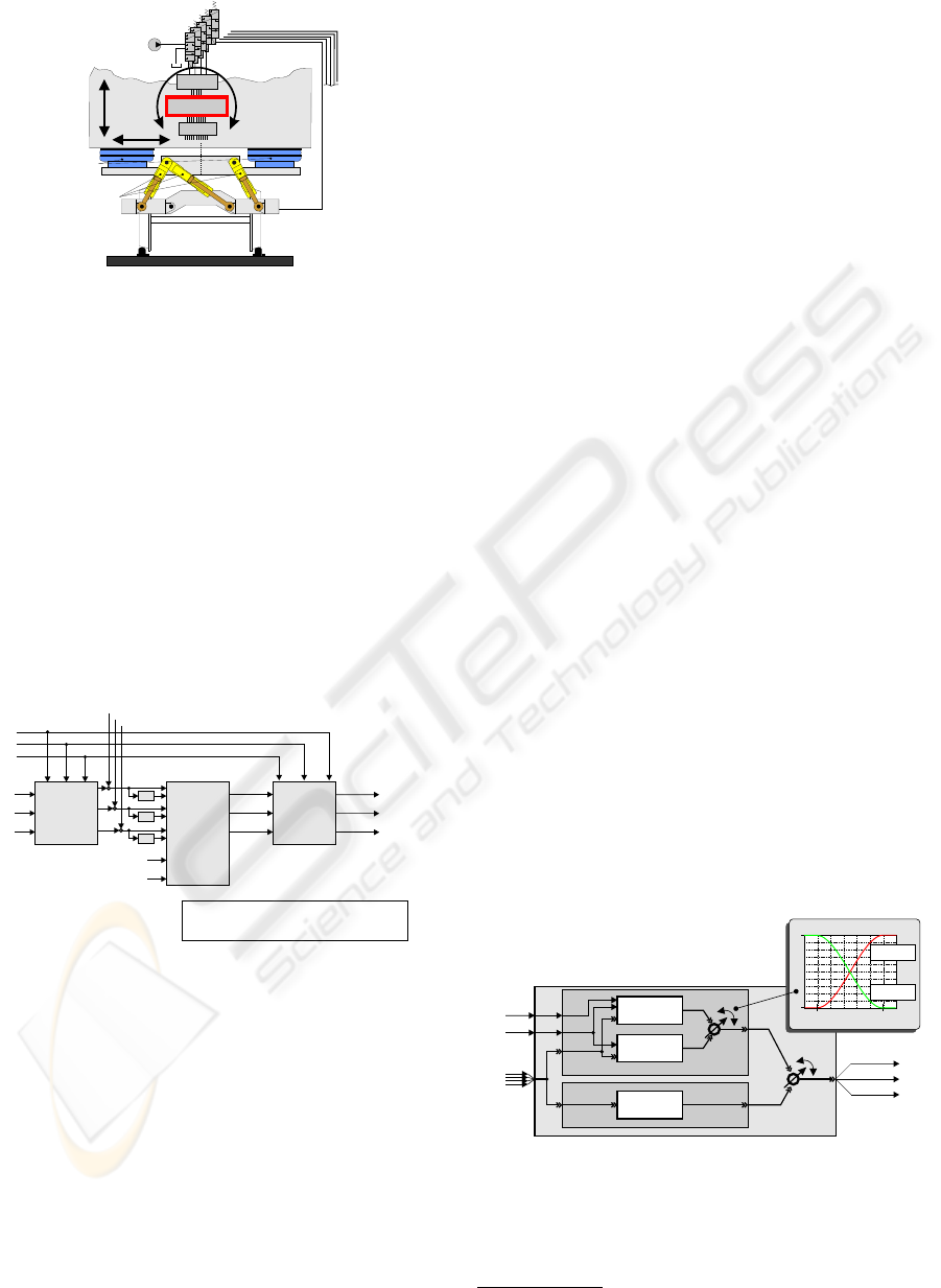
Figure 1 shows a schema of the physical model of
the active vehicle suspension system. The suspen-
sion system of railway vehicles is based on air springs
which can be damped actively by a displacement of
their bases. The active spring-based displacement is
effected by hydraulic cylinders. Three vertical hy-
draulic cylinders, arranged on a plane, move the bases
3
http://www-nbp.upb.de/en
4
http://www.transrapid.de/en
HYBRID UML COMPONENTS FOR THE DESIGN OF COMPLEX SELF-OPTIMIZING MECHATRONIC SYSTEMS
223
A B C
prop.- valves
A / D
controller
D / A
sensors
hydr. pump
car body
hydr. actuators
air springs
to the
actuators
z
y
a
Figure 1: Scheme of the suspension/tilt module
of the air springs via an intermediate frame, the sus-
pension frame. This arrangement allows a damping of
forces in lateral and vertical directions. In addition, it
is also possible to regulate the level of the coach and
add active tilting of the coach body. Three additional
hydraulic cylinders allow a simulation of vertical and
lateral rail excitation (Hestermeyer et al., 2002). The
vital task for the control system is to control the dy-
namical behavior of the coach body. In our example,
we will focus only on the vertical dynamic behavior of
the coach body. The overall controller structure com-
prises different feedback controllers, e.g., for control-
ling the hydraulic cylinder position and the dynamics
of the car body.
reference overall
lateral acceleration
vertical acceleration
decoupling
tuning
forces
coupling
DT
DT
DT
X
Z, A
X
Z, B
X
Z, C
Y
airsp
Z
airsp, L
Z
airsp, R
Y
a
Z
Z
.
Y
.
a
.
F
lift
M
tilt
F
lat.
X
Z, A, ref.
X
Z, B, ref.
X
Z, C, ref.
Y
ref.
Z
ref.
a
ref.
reference values
to cylinder A, B, C
(local controller)
}
x
..
abs.
z
..
abs.
M
tilt
tilt torque
F
lift
lift force
F
lat.
lateral force
Y, aZ,
body coordinates
airsp
L R,
Y, Z , Z
airspring positions
X
Z, A, B, C
cylinder positions
Figure 2: Reference controller
The schema of the reference controller for the over-
all body controller is depicted in Figure 2. The sub-
ordinated controller is not displayed here for reasons
of clarity. The controller essentially consists of the
blocks decoupling, tuning forces, and coupling. In the
block decoupling the kinematics of the cylinders is
converted into Cartesian coordinates for the descrip-
tion of the body motion. The actual control algorithm
is in the block tuning forces. Here the forces are com-
puted which are to affect the mechanical structure.
In the block coupling the forces and torques are con-
verted again into reference values for the subordinated
cylinder controller (Liu-Henke et al., 2000).
A common representation for the modeling of
mechatronic systems which have been employed here
are hierarchical block diagrams. This kind of repre-
sentation has its seeds in control engineering, where
it is used to represent mathematic transfer functions
graphically. It is widely-used in different CAE-
tools. Block diagrams consist generally of function
blocks, specifying function resp. behavior and hier-
archy blocks grouping function and hierarchy blocks.
This allows a structured draft and reduces the over-
all complexity of a block diagram. Between single
blocks exists connections or couplings, which can
have the shape of directed or non-directed links. With
directed links data is exchanged whereas non-directed
ones often describe functional relations or physical
links, such as a link between mass and spring in multi-
body system representation. While parameter opti-
mization can be described using simply an additional
connection for the parameter, the static structure of
block diagrams does not permit to model structural
modifications (Isermann et al., 1992).
We can, however, use special switches or fading
blocks to describe the required behavior. The con-
troller in our example has two normal modes: Ref-
erence and absolute. The controller reference uses a
given trajectory that describes the motion of the coach
body z
ref
= f(x) and the absolute velocity of the
coach body ˙z
abs
(derived from ¨z
abs
). The z
ref
tra-
jectory is given for each single track section. A track
section’s registry communicates this reference trajec-
tory to the vehicle. In case a reference trajectory is
not available, another controller which requires only
the absolute velocity of the coach body ˙z
abs
for the
damping of the coach-body motion has to be used.
Besides the regular modes another controller
named robust is required for an emergency; it must be
able to operate even if neither the reference trajectory
nor the measurement of the coach-body acceleration
are available (see Figure 3).
z
..
z
Z
ref.
abs.
X
Z, A, ref.
X
Z, B, ref.
X
Z, C, ref.
normal
“reference”
“absolute”
failure
“robust”
body control
common
inputs
t
0
t
end
1
0
f (t)
Switch
1-f (t)
Switch
blending curves
Figure 3: Fading between different control modes
For a switching between two controllers one must
distinguish between two different cases: atomic
switching and cross fading.
5
In the case of atomic
5
The structure and type of cross fading depends on the
ICINCO 2004 - SIGNAL PROCESSING, SYSTEMS MODELING AND CONTROL
224
switching the change can take place between two
computation steps. To start the new controller up, it
is often necessary to initialize its states on the basis
of the states of the old controller. In our example, the
switching from the normal block to the failure block
(see Figure 3) can be processed atomically because
the robust controller actually has no state. Different
theoretical works deal with the verification of stabil-
ity in systems with any desired switching processes
(Lygeros et al., 2003). In the simple case of a switch
to a robust controller, stability can be maintained with
the help of condition monitoring (Deppe and Ober-
schelp, 2000).
If, however, the operating points of the controllers
are not identical it will be necessary to cross-fade be-
tween the two controllers. This handling is required in
the normal block depicted in Figure 3, where a transi-
tion between the reference and the absolute controller
is realized. The cross fading itself is specified by a
fading function f
switch
(t) and an additional parame-
ter which determines the duration of the cross fading.
While the outlined modeling style allows to de-
scribe the required behavior, the result is inadequate
because of the following two problems: (1) the differ-
ent operation modes and the possible transitions be-
tween them are more appropriately modeled using a
techniques for finite state systems rather than a set
of blocks scattered all around in the block diagrams
and (2) this style of modeling would require to exe-
cute all alternative controllers in parallel even though
a straight forward analysis of the state space of the re-
sulting finite state system would permit to run only the
blocks which realize the currently active controllers.
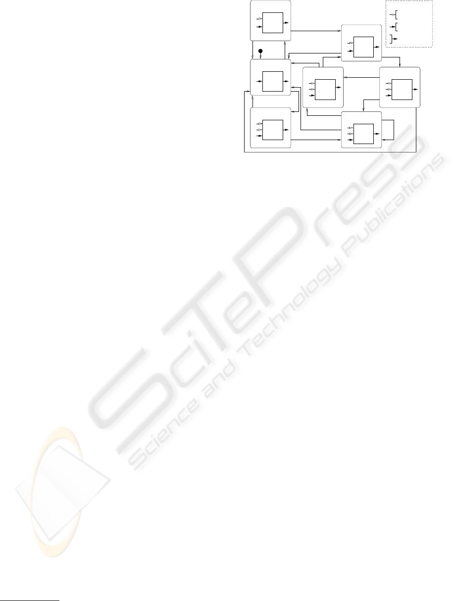
To overcome these problems, hybrid modeling ap-
proaches such as hybrid automata (Henzinger et al.,
1995) can be employed. When modeling the fading
and switching between the different controllers in our
example according to Figure 3, a hybrid automaton
with at least three discrete states – one for each of the
controllers– might be used. These are the locations
Robust, Absolute and Reference in Figure 4. The
locations’ continuous behavior is represented by the
associated controllers. Contrary to the white-filled
arrows, black-filled ones denote the common inputs
which are always available and required by all con-
trollers.
When the automaton resides in the start location
Robust and for instance the ¨z
abs
signal becomes avail-
able (as indicated by the discrete zAbsOK signal),
the location and the controller change to the absolute
mode. As this change requires cross fading an addi-
tional location (FadeRobAbs) is introduced in which
the cross fading is comprised. To specify a fading du-
ration d
1
= [d
1
low
, d
1
up
] an additional state variable
controller types and could lead to complex structures. In
our example we use only output fading.
<Ref
Abs>
<Abs
Ref>
common input
special input
Legend:
common output
<Rob
Abs>
<Rob
Ref>
FadeRobRef
Robust
<Rob>
zRefFailure
Absolute
Reference
zRefOK
zRefOK
FadeRobAbs
FadeRefAbs
<Ref>
FadeAbsRef
<Abs>
zAbsFailure
zAbsFailure
zAbsOK
zAbsFailure
zAbsFailure
zAbsFailure
zRefFailure
zAbsFailure
zAbsOK
z
ref
¨z
abs
t
0
≤ d
4
up
d
4
low
≤ t
0
≤ d
4
up
d
1
low
≤ t
0
≤ d
1
up
t
0
= 0
t
0
≤ d
1
up
z
ref
¨z
abs
z
ref
¨z
abs
z
ref
¨z
abs
¨z
abs
¨z
abs
t
0
≤ d
2
up
t
0
≤ d
3
up
d
3
low
≤ t
0
≤ d
3
up
t
0
= 0
d
2
low
≤ t
0
≤ d
2
up
t
0
= 0
t
0
= 0
Figure 4: Hybrid body control with fading locations
t
c
with
˙
t
c
= 1 is introduced. The reset when en-
tering the fading location FadeRobAbs, its invariant
t
c
≤ d
1
up
and the transition’s guard d
1
low
≤ t
c
≤ d
1
up
guarantee that the fading will take d
1
low
at a minimum
and d
1
up
at a maximum. After completing the fading,
the target location Absolute is entered. The duration
of the other fading transitions is specified similarly. If
the ¨z
abs
signal is lost during fading or during the use
of the absolute-controller, the default location with its
robust control is entered immediately (cf. Figure 4).
In an appropriate self-optimizing design the aim
must be to use the most comfortable controller while
still maintaining the shuttle’s safety. If, for instance,
the absolute controller is in use and the related sensor
fails, the controller may become instable. Thus there
is need for a discrete control monitor which ensures
that only safe configurations are allowed. The moni-
tor which controls the correct transition between the
discrete controller modes must also be coordinated
with the overall real-time processing. In our example,
the reference controller can only be employed when
the data about the track characteristics has been re-
ceived in time by the real-time shuttle control soft-
ware. Trying to also integrate these additional dis-
crete state elements into our hybrid description of the
body control would obviously result in a overly com-
plex description by means of a single hybrid State-
chart which lacks modularity.
4 THE APPROACH
To support the design of complex mechatronic sys-
tems and to overcome the problems of the available
modeling techniques as outlined in the preceding sec-
tion, we introduce in the following informally our ap-
proach for modeling with the UML in Section 4.1,
our notion for hybrid Statecharts in Section 4.2, our
HYBRID UML COMPONENTS FOR THE DESIGN OF COMPLEX SELF-OPTIMIZING MECHATRONIC SYSTEMS
225
notion for hybrid components in Section 4.3, and the
modular reconfiguration in Section 4.4. The exact for-
malization is presented in (Giese et al., 2004).
4.1 Hybrid UML Model
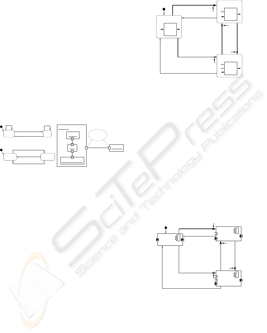
In Figure 5c the overall structural view of our exam-
ple is presented by means of a UML component di-
agram. The Monitor component, that embeds three
components, communicates with the Registry compo-
nent through ports and a communication channel. The
Shuttle-Registration pattern specifies the communica-
tion protocol between Monitor and Registry. The be-
havior of the track section registry which is frequently
contacted by the monitor to obtain the required z
ref
is depicted in Figure 5b. In Figure 5a the sensor’s be-
havior is described by a Statechart.
:Registry
:Monitor
storage : Storage
:BC
:Sensor
Registration
Shuttle−
Pattern
c) Component diagram
a) Sensor
On Off
/ monitor.ok
/ monitor.failure
b) Registry
Default Proceed
shuttle.requestInfo /
Vector zRef)
/ shuttle.sendInfo(
Figure 5: Monitor and its environment (incl. behavior)
The embedded components communicate continu-
ous signals through so called continuous ports, de-
picted by framed triangles whose orientation indicates
the direction of the signal flow, and discrete events
through discrete, non-filled ports.
4.2 Hybrid Statecharts
A look at the hybrid automaton from Figure 4 re-
veals that the explicit fading locations considerably
increase the number of visible locations of the au-
tomaton and make it unnecessarily difficult to under-
stand.
Therefore we propose an extension of UML State-
charts towards Hybrid Statecharts that provide a
short-form to describe the fading. The short-form
contains the following parameters: A source- and a
target-location, a guard and an event trigger, informa-
tion on whether or not it is an atomic switch, and,
in the latter case, a fading strategy (here cross fad-
ing is used for all fading transitions), a fading func-
tion (f
fade
) and the required fading duration interval
d = [d
low
, d
up
] specifying the minimum and maxi-
mum duration of the fading. This short-form is dis-
played in Figure 6. The fading-transitions are visual-
ized by thick arrows while atomic switches have the
shape of regular arrows.
zAbsFailure
zAbsOK
Robust
Reference
Absolute
zRefOK
zAbsFailure
zAbsOK
zRefFailure
<Abs>
<Ref>
<Rob>
d
4
d
2
f
fade
2
f
fade
1
¨z
abs
¨z
abs
z
ref
d
1
d
3
f
fade
3
f
fade
4
Figure 6: Behavior of the body control component
An atomic transition, leaving the source or the tar-
get state of a currently active fading transition, inter-
rupts the execution of the fading transition. In case
of conflicting atomic transitions of the source and tar-
get state, the source state’s transitions have priority by
default.
4.3 Hybrid Components
One serious limitation of today’s approaches for hy-
brid systems is due to the fact that the continuous part
of each location has to have the same set of required
input and provided output variables (continuous in-
terface). To foster the reconfiguration we propose to
describe the different externally relevant continuous
interfaces as well as the transition between them us-
ing hybrid interface Statecharts.
zRefOK
zAbsFailure
zAbsOK
zRefFailure
zAbsOK
[Robust]
[Absolute]
zAbsFailure
[Reference]
d
2
d
3
d
1
d
4
¨z
abs
z
ref
¨z
abs
Figure 7: Interface Statechart of the BC component
The related interface Statechart of the body control
component of Figure 6 is displayed in Figure 7. It
shows that the body control component has three pos-
sible different interfaces. The (continous) ports that
are required in each of the three interfaces are filled
black, the ones that are only used in a subset of the
states are filled white. For all possible state changes,
only the externally relevant information, such as du-
rations and the signals to initiate and to break the tran-
ICINCO 2004 - SIGNAL PROCESSING, SYSTEMS MODELING AND CONTROL
226
sitions, are present.
Interface Statecharts can be employed to ab-
stract from realization details of a component. A
component in our approach can thus be described
as a UML component – with ports with distinct
quasi-continuous and discrete signals and events– by
• a hybrid interface Statechart which is a correct
abstraction of the component behavior (cf. (Giese
et al., 2004)) which determines what signals are
used in what state,
• the dependency relation between the output
and input signals of a component per state of
the interface Statechart in order to ensure only
acyclic dependencies between the components, and
• the behavior of the component usually described
by a single Hybrid Statechart and its embedded
subcomponents (see Section 4.4).
In our example, the BC component is described by
its hybrid interface Statechart presented in Figure 7,
the additionally required information on which de-
pendencies between output and input variables exist
which is not displayed in Figure 7, and its behavior
described by the Hybrid Statechart of Figure 6 where
the required quasi-continuous behavior is specified by
controllers.
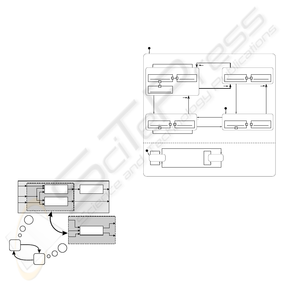
4.4 Modular Reconfiguration
The hybrid statechart from Figure 6, which supports
state-dependent continuous interfaces, does still not
include the case that the employed controllers show
hybrid behavior themselves. Instead, complete sep-
aration of discrete and continuous behavior like in
(Alur et al., 2001; Bender et al., 2002; Henzinger
et al., 1995; K
¨
uhl et al., 2002) is still present.
basic block
basic block
basic block
interchange,
reconfiguration
basic block
hierarchy
hierarchy
hierarchy
A
B
Figure 8: Reconfigurable block diagram
To overcome this limitation, we propose to assign
the required configuration of embedded subcompo-
nents (not only quasi-continuous blocks) to each state
of a Hybrid Statechart by means of UML instance di-
agrams. This idea is motivated by the observation
that the topology of hierarchical block diagrams could
be seen as a tree. With the leafs of this tree repre-
senting the behavior whereas the inner nodes describe
the structure of the system. This distinction between
structure (hierarchy) and function (block) can be used
for the required modular reconfigurable systems. In
our context, a reconfiguration can be understood as a
change in the structure resp. substructure of a block
diagram. It alters the topology of the system; func-
tions are added and/or interlinked anew. Thus to real-
ize modular reconfiguration we only have to provide
a solution to alter the hierarchical elements (cf. Fig.
8). In this manner the required coordination of aggre-
gated components can be described using a modular
Hybrid statechart which alter the configurations of its
hybrid subcomponents (see Figure 9).
:Sensor[Off]:BC[Robust]
storage:Storage
:Sensor[On]:BC[Reference] :Sensor[On]:BC[Absolute]
:BC[Robust] :Sensor[Off]
when(next
Segment)
noData? /
when(nextSegment)
data(Vector zRef)?
when(
!storage.isEmpty())
/ data(Vector zRef)!
after(20)
/ registry.
requestInfo
RefNon
Available
/ noData!
registry.sendInfo(zRef) / storage.add(zRef)
Ref
Available
when(storage.isEmpty())
when(nextSegment)
data(Vector zRef)? /
sensor.ok
RefAvailable
NoneAvailable
sensor.failure
sensor.ok
data(Vector zRef)?
noData?
AbsAvailableAllAvailable
sensor.failure
when(nextSegment)
data(Vector zRef)? /
d
b
d
d
d
a
d
c
Figure 9: Monitor behavior with modular reconfiguration
of the subcomponent BC
Figure 9 specifies the behavior of the control mon-
itor software. The upper AND-state consists of four
locations indicating which of the two signals ¨z
abs
and
z
ref
are available. Some transitions can fire imme-
diately, others are associated with a deadline interval
d = [d
low
, d
up
] specifying how much time a transi-
tion may take minimal and maximal. These transi-
tions are thicker and marked with an arrow and the
intervals (d
a
, . . . , d
d
). The lower branch of the mod-
ular Hybrid statechart communicates with the track
section registry (Figure 5c), frequently requests the
z
ref
function, and puts it in the storage.
In the Hybrid Statechart, every discrete state has
been associated with a configuration of the subcom-
ponents (BC, Sensor, Storage). In the design of these
associations, only the interface description of the em-
bedded component BC (see Figure 7) is relevant and
HYBRID UML COMPONENTS FOR THE DESIGN OF COMPLEX SELF-OPTIMIZING MECHATRONIC SYSTEMS
227

the inner structure can be neglected. Therefore, as
shown in Figure 9, we can assign to each location of
the upper AND-state of the statechart the BC compo-
nent in the appropriate state. E.g., the BC component
instance in state Reference has been (via a visual em-
bedding) assigned to the location AllAvailable of the
monitor where z
ref
as well as ¨z
abs
are available. The
required structure is specified by instances of the Sen-
sor and the Storage component and the communica-
tion links.
The Hybrid Statechart of Figure 9 defines a map-
ping of states to required configurations of the sub-
components. The required synchronization between
the components is accomplished through explicit rais-
ing of the discrete signals defined in Figure 7.
5 RUN-TIME ARCHITECTURE
In order to reach interoperability for mechatronic sys-
tems, which are only alterable within certain limits,
one can use appropriate middleware solutions like
IPANEMA (Honekamp, 1998), which allows abstrac-
tion from hardware details. IPANEMA is a plat-
form concept for distributed real-time execution and
simulation to support rapid prototyping. It allows
a modular-hierarchical organization of tasks or pro-
cesses on distributed hardware.
In order to make interoperability possible also for
hybrid components, which contain the kinds of alter-
ation capability described above, the support of alter-
ation capability by the middleware must be consider-
ably extended. First it is necessary to generate the
models in accordance to their modular-hierarchical
structure. This is the basis for a reconfiguration.
In each discrete location of the system the equa-
tions, that implement the currently active controllers,
have to be employed to compute the correct continu-
ous behavior. Thus in every location of this kind only
the relevant equations have to be evaluated. To reach
this aim, the architecture provides means for every
component to adjust the set of active equation blocks
in such a way that the required reconfiguration of the
component system is efficiently managed.
In the modular execution framework outlined, the
required execution order results from the local eval-
uation dependencies within each component as well
as from their interconnection. It must thus be deter-
mined at deployment-time or run-time.
The continuous nonlinear differential equations are
solved by applying suitable numeric solvers. Com-
putation is time-discrete. Incrementation depends on
the solver and the dynamics of the continuous system.
A time-accurate detection of a continuous condition
is not possible if the controller is coupled with a real
technical system. Thus, we restrict the urgent reaction
to continuous conditions in the hybrid statecharts to a
detection within the desired time slot (cf. (Henzinger
et al., 2003; Stauner, 2002)).
6 CONCLUSION AND FUTURE
WORK
Complex mechatronic systems with self-optimization
are hybrid systems which reconfigure themselves at
run-time. As outlined in the paper, their modeling
can hardly be done by the approaches currently avail-
able. Therefore, we propose an extension of UML
components and Statecharts towards reconfigurable
hybrid systems which supports the modular hierarchi-
cal modeling of reconfigurable systems with hybrid
components and hybrid Statecharts.
The presented approach permits that the needed
discrete coordination can be designed by a software
engineer with extended Statecharts. In parallel, a con-
trol engineer can construct the advanced controller
component which offers the technical feasible recon-
figuration steps. These two views can then be inte-
grated using only the component interface of the con-
troller component.
It is planned to support the presented concepts by
both the CAE tool CAMeL (Richert, 1996) and the
CASE tool Fujaba (Giese et al., 2003). With both
tools, the result of every design activity will be a hy-
brid component. Each of these hybrid components it-
self can integrate hybrid components. The integration
only requires the information given by the component
interface. Additional automatic and modular code
generation for the hybrid models and run-time sup-
port for the reconfiguration will thus result in support
for the modular and component-based development of
self-optimizing mechatronic systems from the model
level down to the final code.
REFERENCES
(2003). UML 2.0 Superstructure Specification. Object Man-
agement Group. Document ptc/03-08-02.
Alur, R., Courcoubetis, C., Halbwachs, N., Henzinger, T.,
Ho, P.-H., Nicollin, X., Olivero, A., Sifakis, J., and
Yovine, S. (1995). The algorithmic analysis of hybrid
systems. Theoretical Computer Science, 138(3-34).
Alur, R., Dang, T., Esposito, J., Fierro, R., Hur, Y., Ivan-
cic, F., Kumar, V., Lee, I., Mishra, P., Pappas, G., and
Sokolsky, O. (2001). Hierarchical Hybrid Modeling of
Embedded Systems. In First Workshop on Embedded
Software.
Bender, K., Broy, M., Peter, I., Pretschner, A., and Stauner,
T. (2002). Model based development of hybrid sys-
tems. In Modelling, Analysis, and Design of Hybrid
ICINCO 2004 - SIGNAL PROCESSING, SYSTEMS MODELING AND CONTROL
228

Systems, volume 279 of Lecture Notes on Control and
Information Sciences, pages 37–52. Springer Verlag.
Conrad, M., Weber, M., and Mueller, O. (1998). Towards
a methodology for the design of hybrid systems in
automotive electronics. In Proc. of the International
Symposium on Automotive Technology and Automa-
tion (ISATA’98).
Deppe, M. and Oberschelp, O. (2000). Real-Time Sup-
port For Online Controller Supervision And Optimi-
sation. In Proc. of DIPES 2000. Workshop on Dis-
tributed and Parallel Embedded Systems, Mechatron-
ics Laboratory Paderborn, University of Paderborn.
F
¨
ollinger, O., D
¨
orscheid, F., and Klittich, M. (1994).
Regelungstechnik - Einf
¨
uhrung in die Methoden und
ihre Anwendung. H
¨
uthig.
Giese, H., Burmester, S., Sch
¨
afer, W., and Oberschelp,
O. (2004). Modular Design and Verification of
Component-Based Mechatronic Systems with Online-
Reconfiguration. In Proc. of 12th ACM SIGSOFT
Foundations of Software Engineering 2004 (FSE
2004), Newport Beach, USA. ACM. (accepted).
Giese, H., Tichy, M., Burmester, S., Sch
¨
afer, W., and Flake,
S. (2003). Towards the Compositional Verification of
Real-Time UML Designs. In Proc. of the European
Software Engineering Conference (ESEC), Helsinki,
Finland. Copyright 2003 by ACM, Inc.
Grosu, R., Krueger, I., and Stauner, T. (1999). Hybrid se-
quence charts. Technical Report TUM-I9914, Techni-
cal University Munich, Munich.
Grosu, R., Stauner, T., and Broy, M. (1998). A modular
visual model for hybrid systems. In Proc. of Formal
Techniques in Real-Time and Fault-Tolerant Systems
(FTRTFT’98), LNCS 1486. Springer-Verlag.
Henzinger, T. A. (2000). Masaccio: A Formal Model for
Embedded Components. In Proceedings of the First
IFIP International Conference on Theoretical Com-
puter Science (TCS), Lecture Notes in Computer Sci-
ence 1872, Springer-Verlag, 2000, pp. 549-563.
Henzinger, T. A., Ho, P.-H., and Wong-Toi, H. (1995).
HyTech: The Next Generation. In Proc. of the 16th
IEEE Real-Time Symposium. IEEE Computer Press.
Henzinger, T. A., Kirsch, C. M., Sanvido, M. A., and Pree,
W. (2003). From Control Models to Real-Time Code
Using Giotto. In IEEE Control Systems Magazine
23(1):50-64, 2003.
Hestermeyer, T., Schlautmann, P., and Ettingshausen,
C. (2002). Active suspension system for railway
vehicles-system design and kinematics. In Proc. of
the 2nd IFAC - Confecence on mechatronic systems,
Berkeley, California, USA.
Honekamp, U. (1998). IPANEMA - Verteilte Echtzeit-
Informationsverarbeitung in mechatronischen Syste-
men. PhD thesis, Universit
¨
at Paderborn, D
¨
usseldorf.
Isermann, R., Lachmann, K.-H., and Matko, D. (1992).
Adaptive Control Systems. Prentice Hall, Herford-
shire.
Kesten, Y. and Pnueli, A. (1992). Timed and hybrid
statecharts and their textual representation. In Proc.
Formal Techniques in Real-Time and Fault-Tolerant
Systems, 2nd International Symposium, LNCS 571.
Springer-Verlag.
K
¨
uhl, M., Reichmann, C., Pr
¨
otel, I., and M
¨
uller-Glaser,
K. D. (2002). From object-oriented modeling to
code generation for rapid prototyping of embedded
electronic systems. In Proc. of the 13th IEEE In-
ternational Workshop on Rapid System Prototyping
(RSP’02), Darmstadt, Germany.
Lamport, L. (1993). Hybrid systems in tla+. Springer.
L
¨
uckel, J., Grotstollen, H., J
¨
aker, K.-P., Henke, M., and
Liu, X. (1999). Mechatronic design of a modular rail-
way carriage. In Proc. of the 1999 IEEE/ASME Inter-
national Conference on Advanced Intelligent Mecha-
tronics (AIM99), Atlanta, GA, USA.
Li, P. Y. and Horowitz, R. (1997). Self-optimizing control.
In Proc. of the 36th IEEE Conference on Decision and
Control (CDC), pages 1228–1233, San Diego, USA.
Liu-Henke, X., L
¨
uckel, J., and J
¨
aker, K.-P. (2000). De-
velopment of an Active Suspension/Tilt System for
a Mechatronic Railway Carriage. In Proc. of the 1st
IFAC-Conference on Mechatronics Systems (Mecha-
tronics 2000), Darmstadt, Germany.
Lygeros, J., Johansson, K. H., Simic´, S. N., Zhang, J., and
Sastry, S. S. (2003). Dynamical Properties of Hy-
brid Automata. In IEEE TRANSACTIONS ON AUTO-
MATIC CONTROL, VOL. 48, NO. 1, JANUARY 2003,
volume 48.
M
¨
uller, C. and Rake, H. (1999). Automatische Synthese von
Steuerungskorrekturen. In KONDISK-Kolloquium,
Berlin.
Richert, J. (1996). Integration of mechatronic design tools
with camel, exemplified by vehicle convoy control de-
sign. In Proc. of the IEEE International Symposium
on Computer Aided Control System Design, Dearborn,
Michigan, USA.
Stauner, T. (2001). Systematic Development of Hybrid Sys-
tems. PhD thesis, Technical University Munich.
Stauner, T. (2002). Discrete-time refinement of hybrid
automata. In Tomlin, C. and Greenstreet, M., edi-
tors, Proceedings of the 5th International Workshop
on Hybrid Systems: Computation and Control (HSCC
2002), volume 2289 of Lecture Notes in Computer
Science, page 407ff, Stanford, CA, USA.
Stauner, T., Pretschner, A., and P
´
eter, I. (2001). Ap-
proaching a Discrete-Continuous UML: Tool Support
and Formalization. In Proc. UML’2001 workshop on
Practical UML-Based Rigorous Development Meth-
ods – Countering or Integrating the eXtremists, pages
242–257, Toronto, Canada.
Wieting, R. (1996). Hybrid high-level nets. In Proceedings
of the 1996 Winter Simulation Conference, pages 848–
855, Coronado, CA, USA.
HYBRID UML COMPONENTS FOR THE DESIGN OF COMPLEX SELF-OPTIMIZING MECHATRONIC SYSTEMS
229
