
REAL WORLD SENSORIZATION AND VIRTUALIZATION FOR
OBSERVING HUMAN ACTIVITIES
Koji Kitamura
Tokyo University of Science
2641, Yamazaki Noda-shi Chiba 278-8510 JAPAN
Yoshifumi Nishida, Makoto Kimura
Digital Human Research Center, National Insititute of Advanced Industrial Science and Technology (AIST)
2-41-6, Aomi Koto Tokyo 135-0064 JAPAN
CREST, JST (Japan Science and Technology Agency)
Hiroshi Mizoguchi
Tokyo University of Science
2641, Yamazaki Noda-shi Chiba 278-8510 JAPAN
Keywords:
Human Behavior Detection, Ubiquitous Computing, Sensorization, Distributed Sensor.
Abstract:
This paper describes a method for robustly detecting and efficiently recognizing daily human behavior in real
world. The proposed method involves real world sensorization for robustly observing his or her behavior using
ultrasonic 3D tags, which is a kind of an ultrasonic location system, real world virtualization for creating a vir-
tual environment through modeling 3D shape of real objects by a stereovision system, and virtual sensorization
of the virtualized objects for quickly registering human activities handling objects in real world and efficiently
recognizing target human activities. As for real world sensorization, this paper describes algorithms for ro-
bustly estimating 3D positions of objects that a human handles. This paper also describes a method for real
world virtualization and virtual sensorization using the ultrasonic 3D tag system and a stereovision system.
1 INTRODUCTION
The observation of human activities in the real world
makes it possible to input personal information into
a computer without any conscious operation of an in-
terface. Human-centered applications based on im-
plicit input of human information require the facility
to observe and recognize activities as a basis. This
paper describes a method for realizing a function for
robustly and efficiently detecting daily human activity
events in the real world.
There are two problems in realizing and utilizing
a function for recognizing human activity in the real
world: the robust observation of a human activity
pattern, and the efficient recognition of meaning of
activity from the observed pattern. Without solving
the first problem, a human activity pattern to be ana-
lyzed cannot be obtained. Without tackling the sec-
ond problem, guaranteeing a solution to the equation
within the time frame demanded by the application is
impossible.
As a method for efficient recognition of activity, the
idea of object-based activity recognition has been pro-
posed (Mizoguchi et al., 1996). In theory, the activity
of handling objects in an environment such as an of-
fice or home can be recognized based on the motion
of the objects. However, when applying the method to
real environments, it is difficult to even achieve an ad-
equate level of object recognition, which is the basis
of the method.
Separating the problems of object recognition and
activity recognition is becoming increasingly realis-
tic with the progress in ubiquitous computing tech-
nology such as microcomputers, sensor, and wireless
networks technology. It has now become possible to
resolve object recognition into the problems of sen-
sorizing objects and tagging the objects with identifi-
cation codes (IDs), and to address activity recognition
separately through the development of applied tech-
nology.
As for robust observation of human activity, this
paper describes a method for ”sensorizing objects in
15
Kitamura K., Nishida Y., Kimura M. and Mizoguchi H. (2004).
REAL WORLD SENSORIZATION AND VIRTUALIZATION FOR OBSERVING HUMAN ACTIVITIES.
In Proceedings of the Sixth International Conference on Enterprise Information Systems, pages 15-20
DOI: 10.5220/0002625400150020
Copyright
c
SciTePress
real world” using a special device. The present au-
thors have developed a three-dimensional ultrasonic
location and tagging system, an ultrasonic 3D tagging
system, for that purpose. In terms of cost and robust-
ness against environmental noise, the ultrasonic sys-
tem is superior to other location techniques such as
visual, tactile, and magnetic systems. A number of ul-
trasonic location systems have already been proposed
or commercialized (Hopper et al., 1999; Shih et al.,
2001). The system presented in the present paper is
developed specifically to address the issue of robust-
ness and accuracy in real time when a person handles
objects having ultrasonic 3D tags.
As for efficient recognition of target activity, this
paper describes a method for ”creating virtual ob-
jects” and ”virtually sensorizing the virtualized ob-
jects” for recognizing target activity. It is important
to create virtual environment extracting essential fea-
tures of the real world so that the created virtual envi-
ronment can eliminate unnecessary process but can
maintain association with target phenomena of the
real world. The method enables a user to quickly reg-
ister target activity to be recognized interactively on a
computer.
This paper is organized as follows. The next sec-
tion describes the method for real world sensoriza-
tion using the ultrasonic 3D tagging system. The de-
veloped ultrasonic 3D tagging system is introduced
briefly. Algorithms for robustly measuring 3D posi-
tions of the objects handled by a person and exper-
imental results are shown. Section 3 describes the
method for creating virtual objects and virtually sen-
sorizing the virtual objects using the ultrasonic 3D
tagging system and a stereovision system.
2 REAL WORLD
SENSORIZATION FOR ROBUST
DETECTION OF HUMAN
ACTIVITY
2.1 Ultrasonic 3D tag
The ultrasonic 3D tagging system developed by the
authors(Nishida et al., 2003) consists of an ultrasonic
receiving section, an ultrasonic transmitting section,
a time-of-flight measuring section, a network section,
and a personal computer. The ultrasonic receiving
section receives ultrasonic pulses emitted from the
ultrasonic transmitter and amplifies the received sig-
nal. The time-of-flight measuring section records the
travel time of the signal from transmission to recep-
tion. The network section synchronizes the system
and collects time-of-flight data from the ultrasonic re-
ceiving section. The positions of objects are calcu-
lated based on more than three time-of-flight results.
The sampling frequency of the proposed system is
50 Hz. The system can keep the sampling frequency
as high as 50 Hz when the number of the target trans-
mitters are less than three or four(Hori et al., 2003). A
user of the system can attach ultrasonic receivers on
arbitrary positions of ceilings or walls and can eas-
ily calibrate the receivers’ positions using a portable
calibration device.
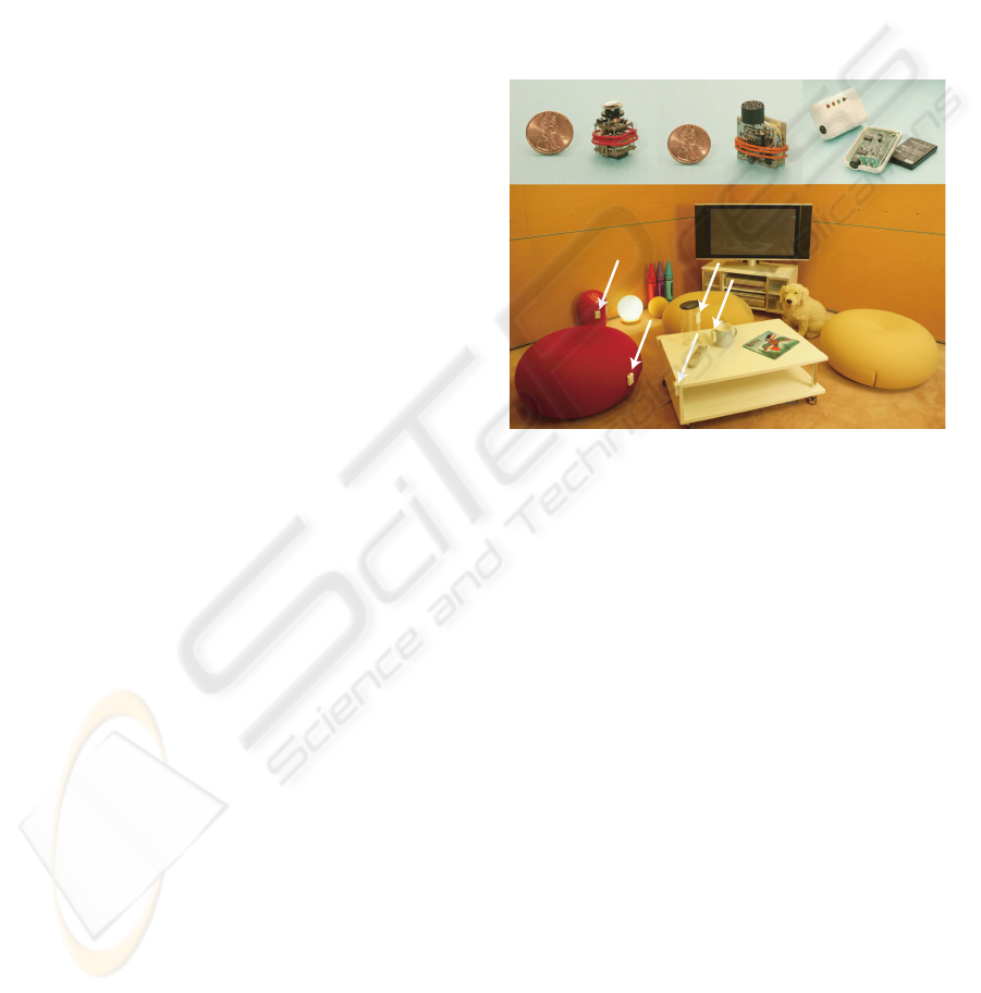
Figure 1 shows the experimental systems for evalu-
ating a function for robust detection of human activity.
The experimental results are shown later. The upper
part of the figure shows a tiny, a small, and a long
life battery type of ultrasonic 3D tag and objects with
ultrasonic 3D tags.
Tiny type
(12x12x20mm)
Small type
(28x20x17mm)
Long life
battery type
(65x44x20mm)
Tag
Figure 1: Ultrasonic 3D tag and sensorized environment
The room was 3.5 × 3.5 × 2.7 m in size, and was
fitted with 307 ultrasonic receivers embedded in the
wall and ceiling. Tags were attached to various ob-
jects, including a cup and a stapler. Some objects
were fitted with two transmitters.
2.2 Multilateration method 1:
linearization of the minimization
problem
Trilateration or multilateration algorithms have been
proposed in the field of aerospace(Ho, 1993;
Manolakis, 1996). This paper presents the multilat-
eration algorithms applicable to a more general case
that multiple ultrasonic receivers are put on arbitrary
positions. Using distance data l
i
, l
j
and the receiver
positions (x
i
, y
i
, z
i
), (x
j
, y
j
, z
j
), we obtain the fol-
lowing spherical equations for the possible position
of the target.
(x
i
− x)
2
+ (y
i
− y)
2
+ (z
i
− z)
2
= l
2
i
, (1)
(x
j
− x)
2
+ (y
j
− y)
2
+ (z
j
− z)
2
= l
2
j
. (2)
By subtracting Eq. (2) from Eq. (1), we obtain an
equation for intersecting planes between the spheres.
ICEIS 2004 - HUMAN-COMPUTER INTERACTION
16
2(x
j
− x
i
)x + 2(y
j
− y
i
)y + 2(z
j
− z
i
)z =
l
2
i
− l
2
j
− x
2
i
− y
2
i
− z
2
i
+ x
2
j
+ y
2
j
+ z
2
j
(3)
By inputting pairs of (i, j) into the above equation,
we obtain simultaneous linear equations, as expressed
by
AP = B, (4)
where P =
Ã
x
y
z
!
, (5)
A =
Ã
2(x
0
− x
1
) 2(y
0
− y
1
) 2(z
0
− z
1
)
2(x
0
− x
2
) 2(y
0
− y
2
) 2(z
0
− z
2
)
2(x
0
− x
3
) 2(y
0
− y
3
) 2(z
0
− z
3
)
!
,(6)
B =
l
2
1
− l
2
0
− x
2
1
− y
2
1
− z
2
1
+ x
2
0
+ y
2
0
+ z
2
0
l
2
2
− l
2
0
− x
2
2
− y
2
2
− z
2
2
+ x
2
0
+ y
2
0
+ z
2
0
l
2
3
− l
2
0
− x
2
3
− y
2
3
− z
2
3
+ x
2
0
+ y
2
0
+ z
2
0
.
.
.
.
(7)
The position (ˆx, ˆy, ˆz) can then be calculated by a
least-squares method as follows.
P = (A
T
A)
−1
A
T
B. (8)
This method minimizes the square of the distance be-
tween the planes expressed by Eq. (3) and the esti-
mated position. In actual usage, the rank of matrix A
must be considered.
2.3 Multilateration method 2:
Robust estimation by RANSAC
Data sampled by the ultrasonic tagging system is
easily contaminated by outliers due to reflections.
Method 1 above is unable to estimate the 3D po-
sition with high accuracy if sampled data includes
outliers deviating from a normal distribution. In the
field of computer vision, robust estimation methods
that are effective for sampled data including outliers
have already been developed. In this work, the ran-
dom sample consensus (RANSAC) (Rousseeuw and
Leroy, 1987; Fishler and Bolles, 1981) estimator is
adopted to eliminate the undesirable effects of out-
liers. The procedure is as follows.
1. Randomly select three distances measured by three
receivers (jth trial).
2. Calculate the position (x
cj
, y
cj
, z
cj
) by trilatera-
tion.
3. Calculate the error ε
cji
for all receivers (i =
0, 1, ..., n) by Eq. (9), and find the median ε
mj
of
ε
cji
.
4. Repeat steps 1 to 3 as necessary to find the combi-
nation of measurements giving the minimum error,
and adopt the corresponding 3D position.
ε
cji
=
¯
¯
¯
l
i
−
p
(x
i
− x
mj
)
2
+ (y
i
− y
mj
)
2
+ (z
i
− z
mj
)
2
¯
¯
¯
(9)
ε
mj
= med
j
|ε
cji
| (10)
(ˆx, ˆy, ˆz) = min ε
mj
(11)
2.4 Robustness to occlusion
As in other measuring techniques such as vision-
based methods, it is necessary to increase the num-
ber of sensors to solve the problem of sensor occlu-
sion, where the line of sight to the target object is ob-
structed by other objects such as walls or room occu-
pants. In the present tagging system, the problem of
occlusion occurs often when a person moves or oper-
ates an object. These situations give rise to two sep-
arate problems; a decrease in the number of usable
sensors for the target, and an increase in reflections
due to obstruction and movement. As one of the most
typical situations where occlusion occurs, this section
focuses on occlusion due to a hand.
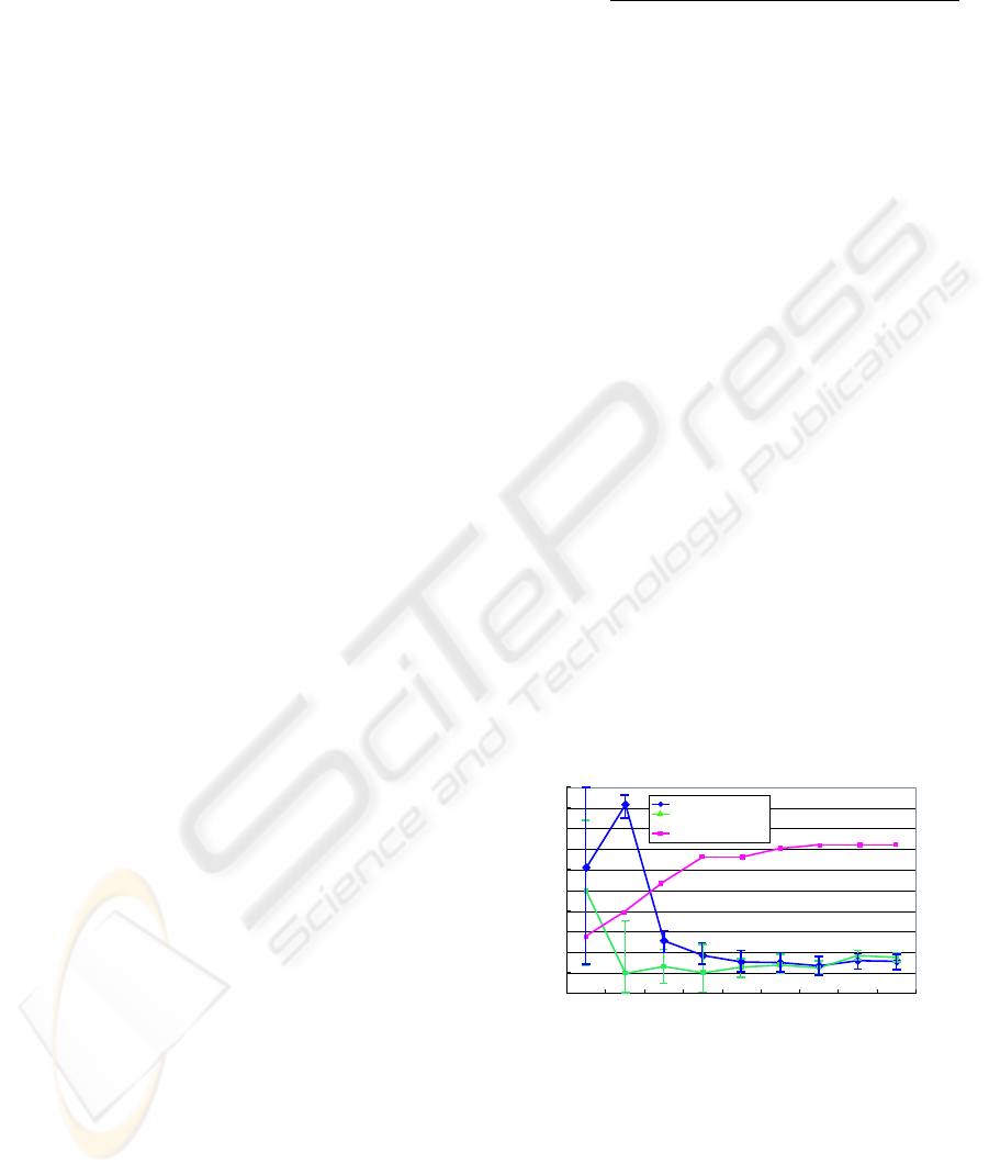
Figure 2 shows how the error increases and the
number of usable sensor decreases as a hand ap-
proaches an object fitted with an ultrasonic trans-
mitter for the least-squares and RANSAC methods.
Although the error increases significantly by both
methods when the hand approaches the object, the
RANSAC method is much less affected than the least-
squares method. This demonstrates that the propor-
tion of outliers increases when occlusion occurs, and
that RANSAC is more robust in this situation because
it can mitigate the effect of such outliers.
Distance from object [cm]
Error [mm]
0
20
40
60
80
100
120
140
160
180
200
10 15 20 25 30 35 40 45 50
Least Square
RANSAC
The number of valid sensors
0
10
20
30
40
The number of valid sensors
Figure 2: Accuracy of the ultrasonic tagging system when
occlusion due to a hand occurs
2.5 Experimental results: robust
detection of human activity
Figure 3 shows the measured trajectory for a person
moving a cup to a chair, the floor, and a desk. The
REAL WORLD SENSORIZATION AND VIRTUALIZATION FOR OBSERVING HUMAN ACTIVITIES
17
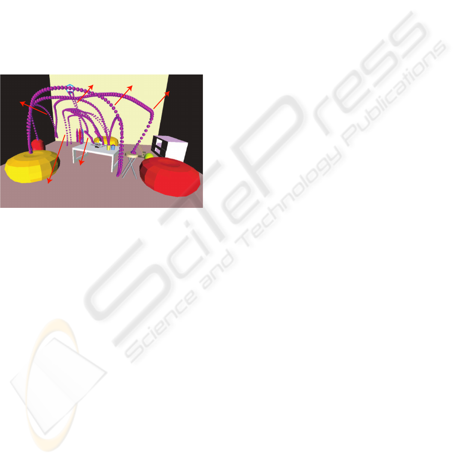
figure demonstrates that the system can robustly mea-
sure the positions of the objects in most places of the
room regardless of occlusion by a hand or body. In
the current system, the sampling frequency is about
50 Hz. Basically this frequency decreases to 50/n Hz
when n objects are being monitored although the sys-
tem can keep the sampling frequency as high as 50 Hz
when the number of the target transmitters is less than
three or four(Hori et al., 2003). However, it is possible
to maintain a high sampling frequency by selecting
which transmitters to track dynamically. For exam-
ple, a transmitter can be attached to a person’s wrist,
and the system can select transmitters in the vicinity
of the wrist to be tracked, thereby reducing the num-
ber of transmitters that need to be tracked at one time
and maintaining the highest sampling frequency pos-
sible.
chair
cup
trash
cell phone
documents
stapler
Figure 3: Robust detection of human activity
3 VIRTUAL SENSORIZATION
FOR QUICK REGISTRATION
AND EFFICIENT
RECOGNITION OF HUMAN
ACTIVITY
3.1 Virtual Sensorizaztion
This section describes a method for virtualizing real
objects and virtually sensorizing the virtualized ob-
jects for efficiently recognizing human acitivities.
The real objects virtualization enables to extract es-
sential geometric features of real objects by simplify-
ing 3D shape of real objects. The 3D shape simplifi-
cation is performed using a stereovision fitted with ul-
trasonic 3D tags in combination with interactive soft-
ware. The software abstracts the shapes of objects in
real world as simple two-dimensional shapes such as
lines, circles, or polygons.
The virtual sensorization of virtualized objects en-
ables to extract essential physical phenomena among
the real objects relating to target activity events. In
order to describe the real world events when a person
handles the objects, the software abstracts the func-
tion of objects as simple phenomena such as touch,
detouch, or rotation. The software adopts the concept
of virtual sensors and effectors to allow the user to de-
fine the function of the objects easily through simple
mouse operations. For example, to define the activity
”put a cup on the desk”, the user simplifies the cup
and the desk as simple two-dimensional models of a
circle and a rectangle using the photo-modeling func-
tion of the software. Using a function for editting vir-
tual sensors, the user then adds a ”touch” virtual sen-
sor to the model of the desk, and adds a ”bar” effector
to the model of the cup. Details of real object virtu-
alization, virtual sensorization of virtualized objects,
registration of target activity, and real time detection
and recognition of the target activity are described in
the following.
3.2 Virtual Sensorizaztion Procedure
Step A: Real object virtualization Figure 7 shows
examples of simplified 3D shape models of objects
such as a tissue, a cup, a desk and a stapler. The cup
is expressed as a circle and the desk as a rectangle.
The simplification is performed using a stereovision
in combination with photo-modeling function (Fig. 6)
of the software.
There is a problem with photo-modeling function
of stereovision. It is difficult to have a target object to
be modeled in stereovision’s sights.To solve the prob-
lem, the authors developed the stereovision system
fitted with multiple ultrasonic 3D tags. We call the
system an ”UltraVision”. Since the UltraVision can
track its position and posture, it is possible to move
the UltraVision freely when the user creates simpli-
fied 3D shape models and the system can integrate
the created models into the world coordinate system.
Concrete process for integrating models is described
in the following.
We assume that the UltraVision is placed at posi-
tion P1 initially and moves from position P1 to posi-
tion P2. The UltraVision has sterevision system and
the ultrasonic 3D tags. There are two coordinate sys-
tems, U1 and C1 as shown in Fig. 4. U1 indicates the
local coordinate system whose origin is the position
of a tag attached on the UltraVision placed at posi-
tion P1, and C1 indicates the local coordinate system
of stereovision. Coordinate systems U2 and C2 are
defined similarly to the case of U1 and U2.
Since the relative location between the stereovi-
sion and tags doen’t change even if the Ultravision
moves, the transformation matrices M
c1u1
and M
c2u2
are constant as follows.
M
c1u1
= M
c2u2
= M
cu
(12)
If M
cu
is known, we can transform the local coordi-
nate value P
c1
and P
c2
to the world coordinate value
ICEIS 2004 - HUMAN-COMPUTER INTERACTION
18
P
w
using the following equation.
P
w
= M
u1w
· M
cu
· P
c1
(13)
P
w
= M
u2w
· M
cu
· P
c2
(14)
Note that M
u1w
and M
u2w
can be calculated using
the positions of multiple tags attached on the UltraV-
ision after the UltraVision moves.
Example of moldeling large room actualy using Ul-
traVision based on this process is Fig. 5.
W
(World coordinate system)
Pc1
Pc2
P
Mc2u2(=Mcu)
Mc1u1(=Mcu)
Mu1w
C2
(Stereovision coordinate system)
U2
(Coordinate system of UltraVision
placed at position P1 )
P1
P2
Pw
Mc1w
C1
(Stereovision coordinate system)
Mc2w
U1
(Coordinate system of UltraVision
placed at position P1 )
Mu2w
Figure 4: Coordinate Conversion in UltraVision system
Chair
Chair
Chair
Table
Desk
TV
Chair
Stapler
Cup
Ultrasonic 3D tag
Stereoscopic camera
Virtualized objects
Objects in real world
UltraVision
Figure 5: UltraVision for virtualizing objects and example
of virtualized objects
Step B: Virtual sensorization of virtualized objects
The software creates a model of an object’s function
by attaching virtual sensors and effectors to the model
created in step A. Virtual sensors and effectors are
prepared in advance by the software and function as
sensors and effectors affecting the sensors on com-
puter. The current system has an ”angle sensor” for
detecting rotation, a ”bar effector” to represent touch,
and a ”touch sensor” for detecting touch. In the right
part of Fig. 8, red indicate a virtual bar effector, and
green indicates a virtual touch sensor. Using simple
mouse operations, it is possible to add virtual sen-
sors/effectors to the 3D shape model.
+OCIGUHTQOUVGTGQUEQRKEECOGTC
5RGEKHKPIEJCTCEVGTKUVKERQKPVU
Figure 6: Photo-modeling by stereovision system
Figure 7: Real object virtualization
Step C: Associating virtual object sensor with
human activity event Human activity can be de-
scribed using the output of the virtual sensors created
in Step B. In Fig. 9, red indicates that the cup touches
the desk, and blue indicates that the cup does not. By
creating a table describing the relationship between
the output of the virtual sensors and the target events,
the system can output symbolic information such as
”put a cup on the desk” when the states of the virtual
sensors change.
Step D: Real time detection and recognition of hu-
man activity event When the software inputs the
$CT'HHGEVQT
6QWEJ5GPUQT
$CT'HHGEVQTVWTPUTGF
YJGPKVKUVQWEJKPIYKVJ6QWEJ5GPUQT
Figure 8: Create model of physical object’s function using
virtual sensors/effectors
REAL WORLD SENSORIZATION AND VIRTUALIZATION FOR OBSERVING HUMAN ACTIVITIES
19
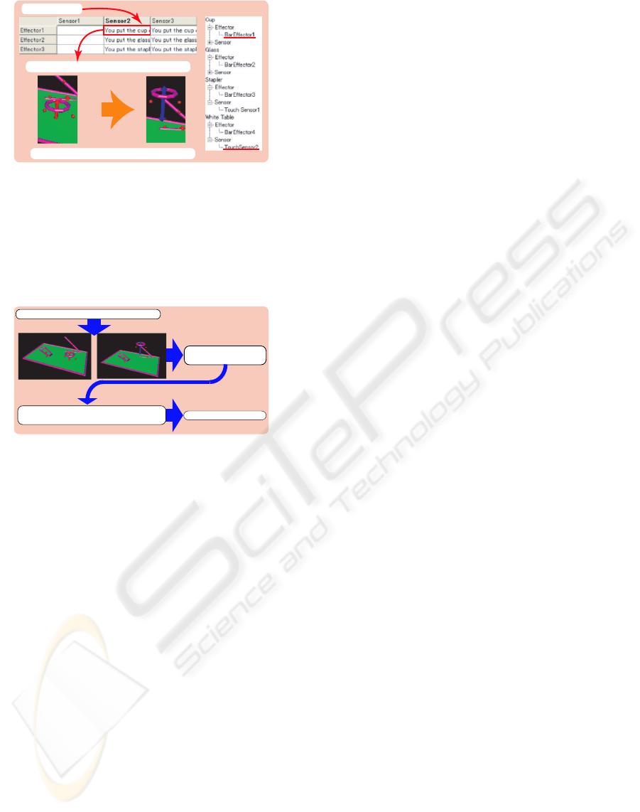
#EVKXKV['XGPV
GZ;QWRWVVJGEWRQPVJGYJKVGVCDNG
$CT'HHGEVQTVQWEJGU6QWEJ5GPUQT
Figure 9: Associate output of virtual sensors with target ac-
tivity event
position data of the ultrasonic 3D tag, the software
can detect the target events using the virtual sensors
and the table defined in Step A to C, as shown in Fig.
10
Human activity events
Output of virtual sensors
(touch state)
3D positions from ultrasonic 3D tag system
Refering table where association of virtual
sensors' output and activity events are defined.
Figure 10: Real time detection and recognition of human
activity by virtual object sensor
4 CONCLUSION
This paper described a method for robustly detecting
human activity in real world and a method for quickly
registering and efficiently recognizing target activity.
The robust detection of human activity is per-
formed by sensorizing objects in real world using an
ultrasonic 3D tagging system, which is a kind of an
ultrasonic location sensor. In order to estimate the
3D position with high accuracy and robustness to oc-
clusion, the authors propose two estimation methods,
one based on a least-squares approach and one based
on RANSAC. The results of experiments conducted
using 48 receivers in the ceiling for a room with di-
mensions of 3.5 × 3.5 × 2.7 m show that it is possible
to improve the accuracy and robustness to occlusion
by increasing the number of ultrasonic receivers and
by adopting a robust estimator such as RANSAC to
estimate the 3D position based on redundant distance
data.
The efficient recognition of human activity in-
volves a method for creating virtual objects using the
ultrasonic 3D tagging system and a stereovision and
a method for virtually sensorizing the created vir-
tual objects interactively on a computer. To verify
the effectiveness of the function, using a stereovi-
sion with ultrasonic 3D tags and interactive software,
the authors registered activity such as ”put a cup on
the desk” and ”staple document” through creating the
simplified 3D shape models of ten objects such as a
TV, a desk, a cup, a chair, a box, and a stapler.
Further development of the system will include re-
finement of the method for measuring the 3D position
with higher accuracy and resolution, and development
of a systematic method for defining and recognizing
human activity based on the tagging data and data
from other sensor systems.
REFERENCES
Fishler, M. and Bolles, R. (1981). Random sample consen-
sus: A paradigm for model fitting with application to
image analysis and automated cartography. Commu-
nication of the ACM, 24:381–395.
Ho, K. (1993). Solution and performance analysis of geolo-
cation by tdoa. IEEE Transaction on Aerospace and
Electronic Systems, 29(4):1311–1322.
Hopper, A., Steggles, P., Ward, A., and Webster, P. (1999).
The anatomy of a context-aware application. In Pro-
ceedings of 5th Annual International Conference Mo-
bile Computing and Networking (Mobicom99), pages
59–68.
Hori, T., Nishida, Y., Kanade, T., and Akiyama, K. (2003).
Improving sampling rate with multiplexed ultrasonic
emitters. In Proceedings of 2003 IEEE International
Conference on Systems, Man and Cybernetics, pages
4522–4527.
Manolakis, D. (1996). Efficient solution and performance
analysis of 3-d position estimation by trilateration.
IEEE Trans. on Aerospace and Electronic Systems,
32(4):1239–1248.
Mizoguchi, H., Sato, T., and Ishikawa, T. (1996). Robotic
office room to support office work by human be-
havior understanding function with networked ma-
chines. IEEE/ASME Transactions on Mechatronics,
1(3):237–244.
Nishida, Y., Aizawa, H., Hori, T., Hoffman, N., Kanade, T.,
and Kakikura, M. (2003). 3-d ultrasonic tagging sys-
tem for observing human activity. In Proceedings of
IEEE International Conference on Intelligent Robots
and Systems, pages 785–791.
Rousseeuw, P. and Leroy, A. (1987). Robust Regression and
Outlier Detection. Wiley, New York.
Shih, S., Minami, M., Morikawa, H., and Aoyama, T.
(2001). An implementation and evaluation of indoor
ultrasonic tracking system. In Proceedings of the 2001
IEICE Domestic General Conference.
ICEIS 2004 - HUMAN-COMPUTER INTERACTION
20
