
A FORMAL APPROACH TO ENTERPRISE MODELING
Yoshiyuki Shinkawa
Department of Media Informatics, Ryukoku University
1-5 Seta Oe-cho Yokotani, Otsu, Shiga, Japan
Keywords:
Enterprise modeling, model consistency, model evaluation, enterprise information systems.
Abstract:
Model driven development for software systems provides us with many advantages in quality, productivity,
or reusability. For accurate modeling, we have to create many kinds of models from various viewpoints.
When applying model driven development to enterprise information systems, those viewpoints include not
only software oriented matters but also business oriented matters. Such complexity in modeling often causes
inconsistency between models. This paper presents a formal and systematic way to create consistent and
integrated enterprise models that reflect those various viewpoints. Set theory, Colored Petri Nets (CPNs), and
Unified Modeling Language (UML) are used for this formalism. In addition, the paper proposes a set theoretic
approach to evaluating consistency between enterprise models. The consistency is discussed in traditional
hierarchical organization and modern matrix organization.
1 INTRODUCTION
Today’s large scale enterprise information systems are
often built up through model based or model oriented
approaches, so that various complicated requirements
are implemented accurately into the information sys-
tems (Frankel, 2003).
Since late 1980’s or early 1990’s, there have been
proposed many kinds of enterprise modeling frame-
works which are equipped with the linkage to soft-
ware development methodologies (Vernadat, 1996).
Those frameworks include CIMASA (Kosanke,
1992), GRAI /GIM (Doumeingts et al., 1994), ARIS
(Scheer, 1999), PERA/GERAM (Williams and Hong,
1998), and so on.
As there are many viewpoints or aspects of an en-
terprise, those frameworks claim to create multiple
models according to the viewpoints, e.g., function, re-
source, data, and so on. However, those models are
often tightly interrelated, and if they are built up inde-
pendently by the isolated different groups, there could
exist a lot of inconsistencies between them.
This paper presents a systematic approach to mak-
ing those enterprise models consistent within an en-
terprise, and gives a formal way to evaluate the con-
sistencies.
2 A BASIC MODEL STRUCTURE
An enterprise is a very complex reality which includes
many resources, activities, processes, rules, regula-
tions, constraints, objectives, missions, organizations,
and so on. Therefore, enterprise models have to repre-
sent such a complex reality, and enterprise modeling
becomes a complicated and difficult task. There are
many consideration points that have to be taken into
account in enterprise modeling.
This paper defines the three groups of them,
namely, modeling lifecycle, decision levels, and kind
of interest. Those groups are referred to as axes
that compose an orthogonal coordination system, and
multiple values or entries are defined on those axes.
The modeling lifecycle axis represents a modeling
process which consists of the requirement analysis
phase, the conceptual modeling phase, and the imple-
mentation phase.
The decision level axis represents managerial hier-
archy in an enterprise, which consists of the strategic
level, the management control level and the opera-
tional level.
The third axis, kind of interest axis, looks differ-
ently depending on which phase is focused on. In the
requirement analysis phase, this axis is composed of
the following business oriented matters, that is, re-
663
Shinkawa Y. (2004).
A FORMAL APPROACH TO ENTERPRISE MODELING.
In Proceedings of the Sixth International Conference on Enter prise Information Systems, pages 663-668
DOI: 10.5220/0002626306630668
Copyright
c
SciTePress
source, organization, function, activity, and process.
On the other hand, in the implementation phase, the
axis consists of more software or system oriented mat-
ters. The models in this phase are expressed as spec-
ifications written in appropriate specification tools.
The paper adopts UML as a specification tool, and
regards kind of interest axis as being composed of the
class diagram, activity diagram, and sequence dia-
gram.
In the conceptual modeling phase, the models
should be neutral from the above two viewpoints, the
business and software viewpoints. The paper regards
the models in this phase as composing the transforma-
tion layer between the business oriented models and
the software oriented models.
This framework resembles CIMOSA cube. How-
ever, CIMOSA cube has a symmetric model structure
between the business view and the information sys-
tem view, on the other hand, the proposed model has
asymmetric model structure between them.
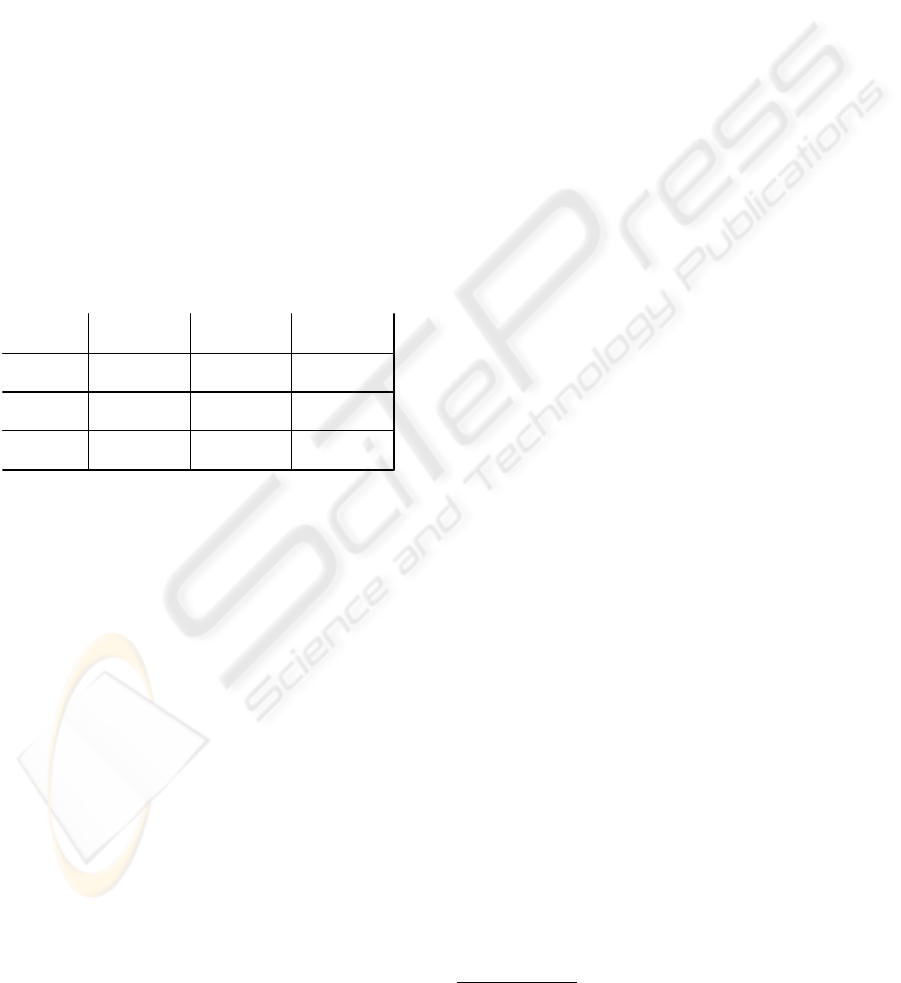
Since three dimensional model frameworks are dif-
ficult to view and understand, the framework in this
paper is divided into two parts.
Strategic
Management
Control
Operational
Requirement
Analysis
Conceptual
Modelig
Implementation
MS
SR
MS
OR
MS
MC
MS
SC
MS
OC
MS
SI
MS
MR
MS
OI
MS
MI
Figure 1: Modeling Framework 1
One is the framework with modeling lifecycle axis
and decision level axis, which is shown in Figure 1.
The modeling process usually follows the MS
Sx
→
MS
Mx
→ MS
Ox
path and MS
yR
→ MS
yC
→ MS
yI
path. However, as for the former path, that is, the top
down deployment, enterprise modeling activities usu-
ally do not participate with it. This deployment is a
part of enterprise design or business design. There-
fore, this paper only deal with the latter path, and it
assumes MS
SR
, MS
MR
, and MS
OR
are modeled in-
dependently.
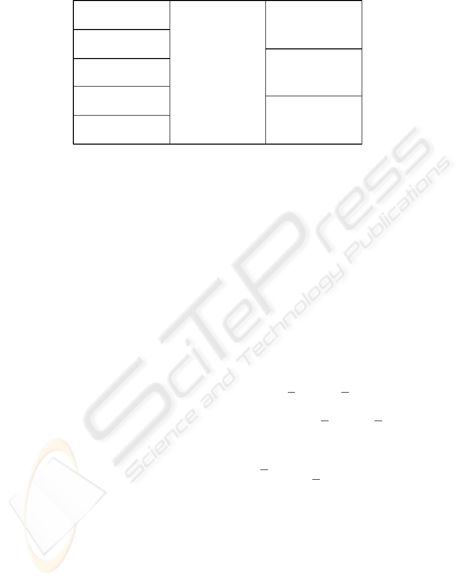
The other is the model framework with the model
lifecycle axis and kind of interest axis, which is shown
in Figure 2.
The relationships between the models in Figure 1
and Figure 2 are as follows.
MS
xR
= {RA
xR
, RA
xO
, RA
xF
, RA
xA
, RA
xP
}
MS
xC
= CM
x
MS
xI
= {IM
xC
, IM
xA
, IM
xS
}
The entries in Figure 2, e.g., RA
xR
and CM
x
, are
called model constituents in this paper.
Once the model framework is defined, the next
steps are creating actual enterprise models which con-
form to the framework, and evaluating or validating
those models. The next section discusses how the
conforming enterprise models are created.
3 CREATING CONFORMING
MODELS
According to the model framework discussed in the
previous section, we have to create the following
models.
1. Resource/Organization/Function/Activity/Process
models for each decision levels, in the requirement
analysis phase. Those are the models from a
business view.
2. Concept models for each decision level, in the con-
ceptual modeling phase.
3. Class diagrams, activity diagrams, and sequence
diagrams for each decision level in the implemen-
tation phase. Those are the models from a informa-
tion system view.
This section shows how those models are created.
3.1 Model Creation from a Business
View
In order to create enterprise models from the business
view rigorously, we first have to define the meaning
of the terms resource, organization, function, activity,
and process.
One of the ways to formalize those terms is to ex-
press them using the rough set theory (Pawlak, 1992).
The first two constituents can be derived us-
ing equivalence relations
1
in the following way
(Shinkawa and Matsumoto, 2001).
1. The definition of resource (RA
xR
)
(a) Let U be a set of all the externally observable
substances in an enterprise. This U is identical
between the decision levels.
(b) A resource is a class of U in terms of set theory,
which is defined by an equivalence relation over
U. This equivalence relation represents a piece
of knowledge on the resources in an enterprise.
(c) Assuming R
i
(x) is an equivalence relation over
U which corresponds to a piece of knowledge at
the decision level x, the resources that are de-
fined by R
i
(x) is denoted by
1
A relation R ⊆ U × U which is reflexive, symmetric
and transitive.
ICEIS 2004 - INFORMATION SYSTEMS ANALYSIS AND SPECIFICATION
664
Requirement
Analysis
Implementation
Conceptual
Modeling
Resource
( RA
xR
)
Organization
( RA
xO
)
Activity
( RA
xA
)
Function
( RA
xF
)
Process
( RA
xP
)
Activity
Diagram
( IM
xA
)
Class
Diagram
( IM
xC
)
Sequence
Diagram
( IM
xS
)
Concept
Model
( CM
x
)
Business View
Information System
View
Figure 2: Modeling Framework 2
U/R
i
(x) = {U
(i)
1
(x), . . . , U
(i)
m
i
(x)}
where U/R
i
(x) represents the classification of
the set U by the equivalence relation R
i
(x).
Each U
(i)
j
means a resource.
(d) The resource model constituent at the decision
level x is a set of the above pieces of knowledge
expressed in the equivalence relations, that is,
RA
xR
= {R
i
(x)}
2. The definition of organization (RA
xO
)
(a) Let V be a set of all the people in an enterprise.
This V is identical between the decision levels.
(b) In the similar way to defining the resource model
constituent, the organization is formalized as
V/Q
i
(x) = {V
(i)
1
(x), . . . , V
(i)
n
i
(x)}
where Q
i
(x) is an equivalence relation over V at
the decision level x.
(c) The organization model constituent at the deci-
sion level x is denoted by
RA
xO
= {Q
i
(x)}
as we did for RA
xR
.
The third model constituent function (RA
xF
) is
defined as a transformation rule between resources.
Such a transformation is formalized as an S-sorted
function of many-sorted algebra (Astesiano et al.,
1999). A function at the decision level x is denoted
by
F
i
(x) : U
i1
(x) × · · · × U
in
i
(x) −→ U
i
(x)
where U
ij
(x) and U
i
(x) are the resources defined at
the decision level x in the above way. The function
model constituent RA
xF
is a set of all the functions
at the decision level x, that is,
RA
xF
= {F
i
(x)}
The fourth model constituent activity (RA
xA
) is
defined as a pair of a function and an organization that
performs the function. At decision level x, an activity
thus defined is denoted by a tuple of a function and an
organization
A
i
(x) = hF
j
(x), V
k
(x)i
and the activity model constituent RA
xA
is defined as
RA
xA
= {A
i
(x)}
The last model constituent process (RA
xP
) is de-
fined as a partially ordered sequence of activities.
Such an activity is expressed as a set of tuples h pre-
ceeding activities, center activity, succeeding activi-
ties i. Therefore a a process at the decision level x
can be denoted by
P
i
(x) = {h
A
(i)
j1
(x), . . . ,
A
(i)
jm
ij
(x), A
(i)
j
(x),
A
(i)
j1
(x), . . . , A
(i)
jn
ij
(x)i}
and the model constituent RA
xP
is denoted by
RA
xP
= {P
i
(x)}
where
A
(j)
k
(x) and A
(j)
k
(x) represent a preceding ac-
tivity and a succeeding activity of the activity A
(j)
i
(x)
respectively. The m
ij
or the n
ij
is zero if A
(i)
j
(x) is
an initial or a terminal node.
3.2 Model Creation from a
Conceptual View
This paper uses Colored Petri Nets (CPNs) for con-
ceptual modeling. CPNs can be conveniently used for
expressing workflows and business processes (Aalst
and Hee, 1995)(Aalst, 1998). In our case, the pro-
cesses correspond to them, and the processes include
all the model constituents by definition.
A FORMAL APPROACH TO ENTERPRISE MODELING
665

CPNs are one of the enhancements of Petri nets,
and formally defined as follows (Jensen, 1997).
CPN=(S, P, T, A, N, C, G, E, I) ,
where
S : a finite set of non-empty types, called color
sets,
P : a finite set of places,
T : a finite set of transitions,
A : finite set of arcs P ∩T = P ∩A = T ∩A = ∅,
N : node function A → P × T ∪ T × P ,
C : a color function P → S,
G : a guard function T → expression,
E : an arc expression function A → expression
and
I : an initialization function : P → closed ex-
pression.
In order to transform a process in RA
xP
into a
CPN model, we introduce the following basic rules
(Shinkawa and Matsumoto, 2000). Let the original
process be
P
i
(x) = {hA
(i)
j1
(x), . . . ,
A
(i)
jm
ij
(x), A
(i)
j
(x),
A
(i)
j1
(x), . . . , A
(i)
jn
ij
(x)i}
and let the resultant CPN model be
CPN
i
(x) =
¡
S
i
(x), P l
i
(x), T
i
(x), A
i
(x),
N
i
(x), C
i
(x), G
i
(x), E
i
(x), I
i
(x)
¢
where x is a decision level.
1. T (x) is a set of the activities that occur in the P
i
(x)
as A,
A, or A.
2. P l
i
(x) is a set of the organizations that are included
in A, A, or A in the form of
A
i
(x) = hF
j
(x), V
k
(x)i,
where V
k
(x) represents an organization.
3. A tuple hV
(i)
jk
(x), A
(i)
j
(x)i, is a member of N(x),
iff A
(i)
jk
(x) = h
F
(i)
jk
(x),
V
(i)
jk
(x)i is one of the pre-
ceding activities of A
(i)
j
(x).
4. A tuple hA
(i)
j
(x), V
(i)
jk
(x)i, is a member of N(x),
iff A
(i)
jk
(x) = hF
(i)
jk
(x), V
(i)
jk
(x)i is one of the suc-
ceeding activities of A
(i)
j
(x).
5. The union of the above two sets of tuples,
N(x) = {hV
(i)
jk
, A
(i)
j
(x)i}
S
{hA
(i)
j
(x), V
(i)
jk
i}
determines the structure of the CPN model.
6. S
i
(x) = U/RA
xR
and P l
i
(x) = V/RA
xO
, where
U/RA
xR
means all the classes made by the equiv-
alence relations included in RA
xR
.
7. A
i
(x) is a set of arc names, and we can give arbi-
trary names to the arcs defined by N
i
(x).
8. C
i
(x) represents the associated colors to each
place, and it means the required resource types for
the transition that receive the tokens from the place.
This association is imbedded in each
A
i
(x) = hF
j
(x), V
j
(x)i and
F
j
(x) : U
j1
(x) × · · · × U
jm
j
(x) −→ U
j
(x).
¡
U
jk
(x) ∈ C
i
(x)
¢
9. E(x), an arc expression function represents the
function that each activity performs, therefore it
can be derived from A
i
(x) = hF
j
(x), V
k
(x)i.
10. G
i
(x), a guard function, and I
i
(x), an initialization
function, are derived from the constraint statements
C.
3.3 Model Creation from a
Information System View
CPN models are too abstract to be implemented into
enterprise information systems. In addition, most
software developers, e.g., programmers, system de-
signers, or systems engineers, seem not to be familiar
with CPN. Therefore, those models should be trans-
formed into the models written in more appropriate
methods for software development. UML (Unified
Modeling Language) is one of the most popular tools
to design software and systems.
Although many kinds of diagrams are provided by
UML, the most essential ones for enterprise modeling
are class diagram, activity diagram, and sequence di-
agram. Some other diagrams, such as component dia-
grams, deployment diagrams, or state chart diagrams,
are to be created after the enterprise modeling, while
use case diagrams are considered to be embedded in
CPN models.
The roles of places, transitions, arc expression
functions, and guard functions discussed in the pre-
vious section suggests the following transformation
rules from a CPN model to UML models.
1. A class is an entity that provides some functional-
ity. This role is taken by a pair of an input place
and a transition in our CPN models. Therefore,
each pair of an input place and a transition com-
pose a class, where arc expression functions are re-
garded as methods. The attributes in the class are
defined by colors associated to the tokens that make
the transition fire.
2. The role of an activity in UML is approximately the
same as that of a transition in CPN models. Since
activity diagrams show the execution sequences of
those activities, they are formed by deleting the
places from the CPN models, and connecting the
transitions directly.
3. The role of a sequence diagram is to describe the
message passing between objects. The places in
ICEIS 2004 - INFORMATION SYSTEMS ANALYSIS AND SPECIFICATION
666

CPN models can be regarded as those objects that
send and receive messages as color tokens. There-
fore, sequence diagrams are formed by deleting the
transitions from the CPN models, and connecting
the places directly.
Since the symbols and notation of CPN and UML
are different from each other, we have to transform
them into appropriate forms that conform to UML.
The above UML models are to be treated as the proto-
types of IM
xC
, IM
xA
, and IM
xS
in Figure 2. Those
models should be refined according to the actual con-
straints of the information systems to be built.
4 MODEL CONSISTENCY
The previous discussion on model transformation
does not take the model consistency along decision
level axis into account. This section deals with the
consistency along that axis.
4.1 Hierarchical Enterprise
Structure
In the requirement analysis phase, all the model
sets are expressed as a set of equivalence relations
or sets of tuples, regardless of the decision levels.
Since the decision level axis represents generaliza-
tion/specialization as we discussed in section 2, the
consistency along this path can be defined by relations
of inclusion as follows.
1. Resource and Organization
Let RA
xR
= {R
i
(x)} and RA
xO
= {Q
i
(x)} be
the model constituents of resources and organiza-
tions respectively, where x represents a decision
level. For model consistency between the decision
levels,
∀R
i
(O) ∈ RA
OR
∃R
j
(M) ∈ RA
MR
∃R
k
(S) ∈ RA
SR
[R
i
(O) ⊂ R
j
(M) ⊂ R
k
(S)]
and
∀Q
i
(O) ∈ RA
OO
∃Q
j
(M) ∈ RA
MO
∃Q
k
(S) ∈ RA
SO
[Q
i
(O) ⊂ Q
j
(M) ⊂ Q
k
(S)]
must hold. Those conditions represent that the ex-
tent of resources or organizations in a higher deci-
sion level must be wider than that in a lower level.
2. Function
Let RA
xF
= {F
i
(x)} be a model constituent of
functions. For consistency,
∀F
i
(O) ∈ RA
OF
∃F
j
(M) ∈ RA
MF
∃F
k
(S) ∈ RA
SF
[F
i
(O) ⊂ F
j
(M) ⊂ F
k
(S)]
must hold. This condition also represents the extent
of functions between the decision levels.
3. Activity
Let RA
xA
= {A
i
(x)} = {hF
j
(x), V
k
(x)i} be a
model constituent of activities. For consistency
∀A
i
(O) = hF
j
(O), V
k
(O)i ∈ RA
OA
∃A
i
0
(M) = hF
j
0
(M), V
k
0
(M)i ∈ RA
MA
∃A
i
00
(S) = hF
j
00
(S), V
k
00
(S)i ∈ RA
SA
[F
j
(O) ⊂ F
j
0
(M) ⊂ F
j
00
(S)
V
V
k
(O) ⊂ V
k
0
(M) ⊂ V
k
00
(S)]
must hold.
4. Process
Let
RA
xP
= {P
i
(x)} =
©
{h
A
(i)
j1
(x), . . . ,
A
(i)
jm
ij
(x),
A
(i)
j
(x), A
(i)
j1
(x), . . . , A
(i)
jn
ij
(x)i}
ª
be a model constituent of processes. For consis-
tency,
∀P
i
(O) = {h
A
(i)
j1
(O), . . . , A
(i)
jm
ij
(O),
A
(i)
j
(O), A
(i)
j1
(O), . . . , A
(i)
jn
ij
(O)i}
∈ RA
OP
∃P
i
0
(M) = {h
A
(i
0
)
j
0
1
(M), . . . ,
A
(i
0
)
j
0
m
i
0
j
0
(M),
A
(i
0
)
j
0
(M), A
(i
0
)
j
0
1
(M), . . . , A
(i
0
)
jn
i
0
j
0
(M)i}
∈ RA
MP
∃P
i
00
(S) = {h
A
(i
00
)
j
00
1
(S), . . . ,
A
(i
00
)
j
00
m
i
00
j
00
(S),
A
(i
00
)
j
00
(S), A
(i
00
)
j
00
1
(S), . . . , A
(i
00
)
jn
i
00
j
00
(S)i}
∈ RA
SP
[
¡
A
(i)
jk
(O) ⊂ A
(i
0
)
i
0
j
0
(M) ⊂
A
(i
00
)
i
00
j
00
(S)
¢
V
¡
A
(i)
j
(O) ⊂ A
(i
0
)
j
0
(M) ⊂ A
(i
00
)
j
00
(S)
¢
V
¡
A
(i)
jk
(O) ⊂ A
(i
0
)
i
0
j
0
(M) ⊂ A
(i
00
)
i
00
j
00
(S)
¢
]
must hold.
The above conditions assure the model consistency
along the decision level axis in the requirement anal-
ysis phase on the modeling lifecycle axis, The model
consistency in this phase guarantee the model consis-
tency in the conceptual modeling phase and the imple-
mentation phase, since all the models in those phases
are derived consistently from the model constituents
in the requirement analysis phase.
4.2 Non-Hierarchy Enterprise
Structure
The model consistency discussed in the previous
section assumes the simple hierarchical organization
structure, and the decision level axis represents gener-
alization/specialization process. In modern business
environment, many enterprises adopt more efficient
forms of organization for swift decision-making. A
typical one of those new organization forms is ma-
trix organization. A matrix organization is an orga-
nization which has multi-dimensional decision paths.
The simplest form of the matrix organization is a two-
dimensional organization, e.g., an organization with
A FORMAL APPROACH TO ENTERPRISE MODELING
667

the functional decision path and the regional decision
path.
In matrix organization, the decision level axis splits
into the multiple axes corresponding to the deci-
sion paths defined in that organization. In addition,
while the classical organization theory proposed three
managerial levels or decision levels, today’s complex
enterprise organization includes variable number of
those levels, more or less than three. From those dis-
cussions, the models of an enterprise with such an or-
ganization are formalized as follows.
1. Let the decision path axes be X
1
, . . . , X
p
, where
each path X
i
includes q
i
levels α
1
, . . . , α
q
i
.
2. Each model set MS
xy
shown in Figure 1 is
extended to the multi-dimensional expression
MS
y
(x
1
, . . . , x
p
), whrer x
i
∈ X
i
.
3. Each model RA
xy
in Figure 2 is extended to the
multi-dimensional expression RA
y
(x
1
, . . . , x
p
).
4. Each model CM
x
in Figure 2 is extended to the
multi-dimensional expression CM(x
1
, . . . , x
p
).
5. Each model IM
xy
in Figure 2 is extended to the
multi-dimensional expression IM
y
(x
1
, . . . , x
p
).
Each decision path axis X
i
can be regarded as a to-
tally ordered set X
i
= {α
i1
, . . . , α
iq
i
}, where
∀j, k(j < k)[α
ij
≺ α
ik
]
holds. This total order “≺” represents the hierarchy
or reporting line along this decision path. The model
sets in the requirement analysis phase can be expressd
as
MS
R
(~x) = {RA
R
(~x), RA
O
(~x), RA
F
(~x),
RA
A
(~x), RA
P
(~x)}
where ~x = hx
1
, . . . , x
p
i, and each RA
y
(~x) represents
the same objects as defined in Section 3.1.
5 CONCLUSION
In this paper, a formal approach to enterprise model-
ing and model consistency evaluation was presented.
An asymmetric model framework between a business
view and a system view was used to create and eval-
uate enterprise models. This framework is composed
of three orthogonal axes that represent different types
of concerning points for modeling.
The paper dealt with enterprise modeling within a
single enterprise. However, the Internet technologies
are enabling enterprise collaborations in a rapid pace.
Therefore, it is required to enhance the proposed
approach to modeling such enterprise collaborations
as Supply Chain Management (SCM), e-business, e-
marketplace, or virtual enterprises.
REFERENCES
Aalst, W. M. P. (1998). Three good reasons for using a petri-
net-based workflow management system. In Informa-
tion and process integration in enterprises: Rethink-
ing documents, pages 161–182, pp.161-182. Kluwer
Academic Publishers.
Aalst, W. M. P. and Hee, K. M. (1995). Framework for
business process redesign. In Proc. of 4th Workshop
on Enabling Technologies: Infrastructure for Collab-
orative Enterprises (WET ICE ’95), pp.36-45. IEEE.
Astesiano, E., Kreowski, H. J., and Bruckner, B. K.
(1999). Algebraic Foundation of System Specification.
Springer.
Doumeingts, G., Chen, D., Vallespir, B., and Fenic, R.
(1994). Grai integrated methodology (gim) and its
evolutions: a methodology to design and specify ad-
vanced manufacturing systems. In IFIP Transac-
tions B: Computer Applications in Technology B-14
pp.101-117.
Frankel, D. S. (2003). Model Driven Architecture: Applying
MDA to Enterprise Computing. John Wiley & Sons.
Jensen, K. (1997). Coloured Petri Nets Volume 1-3.
Springer.
Kosanke, K. (1992). Cimosa–a european development for
enterprise integration part 1: An overview. In Enter-
prise Integration Modeling (Edited by C.G. Petrie Jr),
pp.179-188. MIT Press.
Pawlak, Z. (1992). Rough Sets : Theoretical Aspects of
Reasoning About Data. Kluwer Academic Publishers.
Scheer, A. W. (1999). ARIS–Business Process Modeling.
Springer.
Shinkawa, Y. and Matsumoto, M. J. (2000). Knowledge-
based software composition using rough set the-
ory. In IEICE Trans. on Inf. and Syst, Vol.E83-D.
No.4,pp.691-700. IEICE.
Shinkawa, Y. and Matsumoto, M. J. (2001). Identifying
the structure of business processes for comprehensive
enterprise modeling. In IEICE Trans. on Inf. and Syst,
Vol.E84-D. No.2, pp.239-248. IEICE.
Vernadat, F. B. (1996). Enterprise Modeling and Integra-
tion. Chapman and Hall, Upper Saddle River,NJ.
Williams, T. J. and Hong, L. (1998). Pera and geram en-
terprise reference architectures in enterprise integra-
tion. In Proc. of Design and Information Infrastruc-
ture and Systems for Manufacturing, pp3-30. Kluwer
Academic Publishers.
ICEIS 2004 - INFORMATION SYSTEMS ANALYSIS AND SPECIFICATION
668
