DEPTH GRADIENT IMAGE BASED ON SILHOUETTE
A Solution for Reconstruction of Scenes in 3D Environments
Pilar Merchán
Escuela de Ingenierías Industriales,Universidad de Extremadura, Avda. Elvas,s/n, 06071Badajoz, Spain
Antonio Adán
Escuela Superior de Informatica, Universidad de Castilla La Mancha, 13071 Ciudad Real, Spain
Santiago Salamanca
Escuela de Ingenierías Industriales,Universidad de Extremadura, Avda. Elvas,s/n, 06071Badajoz, Spain
Keywords: 3D Computer Vision, Reconstruction, 3D Object Recognition,
Range Image Processing.
Abstract: Greatest difficulties arise in 3D environments when we h
ave to deal with a scene with dissimilar objects
without pose restrictions and where contacts and occlusions are allowed. This work tackles the problem of
correspondence and alignment of surfaces in such a kind of scenes. The method presented in this paper is
based on a new representation model called Depth Gradient Image Based on Silhouette (DGI-BS) which
synthesizes object surface information (through depth) and object shape information (through contour).
Recognition and pose problems are efficiently solved for all objects of the scene by using a simple matching
algorithm in the DGI-BS space. As a result of this the scene can be virtually reconstructed. This work is part
of a robot intelligent manipulation project. The method has been successfully tested in real experimentation
environments using range sensors.
1 INTRODUCTION
1.1 Statement of the Problem in a
Practical Environment
The work presented in this paper is integrated in a
robot-vision project where a robot has to carry out
an intelligent interaction in a complex scene. The 3D
vision system takes a single range image of the
scene which is processed to extract information
about the identity of the objects and their pose in the
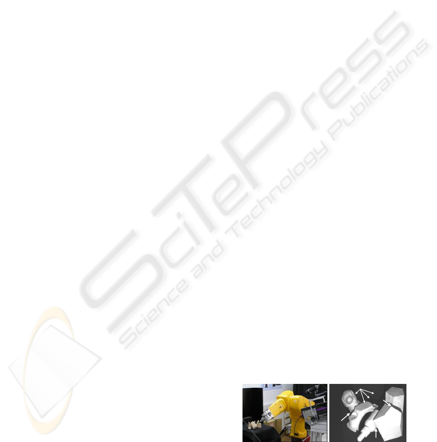
scene. Figure 1a) presents the real environment with
the components that we are using in our work: the
scene, the immobile vision sensor and the robot. In
the worst case, the complexity of this scene includes:
no shape-restrictions, shades, occlusion, cluttering
and contact between objects. Figure 1b) shows a
prototype of a scene that we have dealt with.
An intelligent interaction (grasping, pushing,
t
ouching, etc) of a robot in such a scene is a complex
task which involves several and different research
fields: 3D image processing, computer vision and
robotics. There are three main phases in the
interaction: segmentation of the scene into their
constituent parts, recognition and pose of the objects
and robot planning/interaction. In this paper we
specifically present an efficient recognition/pose
solution that allows us to know the layout of the
objects in the scene. This information is essential to
carry out a robot interaction in the scene. Therefore
we have integrated this work as a part of the general
project which is being currently used in real
applications.
Arbitrary positions
contact
sh
adow
occlusion
Arbitrary positions
contact
sh
adow
occlusion
Arbitrary positions
Figure 1: a) Robot interaction in the scene. b) Example of
com
plex scene.
112
Merchán P., Adán A. and Salamanca S. (2006).
DEPTH GRADIENT IMAGE BASED ON SILHOUETTE - A Solution for Reconstruction of Scenes in 3D Environments.
In Proceedings of the Third International Conference on Informatics in Control, Automation and Robotics, pages 112-119
DOI: 10.5220/0001214401120119
Copyright
c
SciTePress

1.2 Previous Work on Contour and
Surface Based Representations
Object recognition in complex scenes is one of the
current problems in the computer vision area. In a
general sense, the recognition involves identifying
an unknown object, which is arbitrarily posed,
among a set of objects in a database. In 3D
environments, recognition and positioning are two
different concepts that can be separately handled
when complete information of the scene is available.
Nevertheless, if only a part of the object is sensed in
the scene, recognition and pose appear closely
related. In others words, the object is recognized
through the computation of the best alignment
scene-model.
As we know, there is a wide variety of solutions
to recognize 3D objects. Most of them use models
based on geometrical features of the objects and the
solution depends on the feature matching procedure.
Among the variety of methods are those that
recognize 3D objects by studying sets of 2D images
of the object from different viewpoints. Some of
these methods rely on extracting the relevant points
of a subset of canonical views of the object (Roh,
2000; Rothwell, 1995). The main drawback of these
techniques is that the detection of relevant points
may be sensitive to noise, illumination changes and
transformations. There are also strategies that use
shape descriptors instead of relevant points of the
object (Trazegnies, 2003; Xu, 2005) but most of
them need the complete image of the object to solve
the recognition problem.
Matching and alignment techniques based on
contour representations are usually effective in 2D
environments. Thus, different techniques based on:
Fourier descriptors (Zahn, 1972), moment invariants
(Bamieh, 1986), spline curves (Alferez, 1999),
wavelets (Lee, 2000) and contour curvature
(Mokhararian, 1997; Zabulis, 2005) can be found in
the literature. Nevertheless, in 3D environments
these techniques have serious limitations. The main
restrictions are: limited object pose, viewpoint
restrictions (usually reduced to one freedom degree)
and occlusions not allowed. Main troubles of the
contour based techniques occur due to the fact that
the silhouette’s information may be insufficient and
ambiguous. Thus, similar silhouettes might
correspond to different objects from different
viewpoints. Consequently, a representation based on
the object contour may be ambiguous, especially
when occlusion circumstances occur. As a result, the
matching problem is usually tackled by means of
techniques that use surface information instead of
contour information.
Surface matching algorithms solve the recognition
problem using 3D sensors. In this case two different
processes arise: surface correspondence and surface
registration. Surface correspondence is the process
that establishes which portions of two surfaces
overlap. Using the surface correspondence,
registration computes the transformation that aligns
the two surfaces. Obviously the correspondence
phase is the most interesting part of the algorithm.
Recently Planitz et al. (Planitz, 2005) have published
a survey about these techniques. Next, we will
present a brief summary of the most important
works that are closely related to ours.
Chua and Jarvis code surrounding information at a
point of the surface through a feature called Point
Signature (Ching, 1997). Point signature encodes
information on a 3D contour of a point
P of the
surface. The contour is obtained by intersecting the
surface of the object with a sphere centered on
P.
The information extracted consists of distances of
the contour to a reference plane fixed to it. So, a
parametric curve is computed for every
P and it is
called point signature. An index table, where each
bin contains the list of indexes whose minimum and
maximum point signature values are common, is
used for making correspondences. The best global
correspondence produces the best registration.
Johnson and Hebert (Johnson, 1999) have been
working with polygonal and regular meshes to
compare two objects through Spin Image concept.
Spin image representation encodes information not
for a contour but for a region around a point
P. Two
geometrical values
(α,β) are defined for the points of
a region and a 2D histogram is finally constructed.
In (Yamany, 2002) a representation, that stores
surface curvature information from certain points,
produces images called Surface Signatures at these
points. As a result of this, a standard Euclidean
distance to match objects is presented. Surface
signature representation has several points in
common with spin image. In this case, surface
curvature information is extracted to produce 2D
images called surface signature where 2D
coordinates correspond to other geometrical
parameters related to local curvature. Geometric
Histogram matching (Ashbrook, 1998) is a similar
method that builds another kind of 2D geometric
histogram.
Zhang (Zhang, 1999) also uses 2D feature
representation for regions. In this case a curvature-
based representation is carried out for arbitrary
regions creating harmonic shape images. Model and
scene representations are matched and the best local
match is chosen. Adán et al. (Adán, 2004) present a
new strategy for 3D objects recognition using a
DEPTH GRADIENT IMAGE BASED ON SILHOUETTE - A Solution for Reconstruction of Scenes in 3D Environments
113
flexible similarity measure that can be used in partial
views. Through a new curvature feature, called Cone
Curvature, a matching process yields a coarse
transformation between surfaces. Campbell and
Flynn (Campbell, 2002) suggest a new local feature
based technique that selects and classify the highly
curved regions of the surface. These surfaces are
divided up into smaller segments which define a
basic unit in the surface. The registration is
accomplished through consistent poses for triples of
segments.
Cyr and Kimia (Cyr, 2004) measure the similarity
between two views of the 3D object by a metric that
measures the distance between their corresponding
2D projected shapes. Liu, et al. (Xinguo, 2003)
propose the Directional Histogram Model for objects
that have been completely reconstructed.
Most methods described impose some kind of
restriction related to 3D sensed information or the
scene itself. The main restrictions and limitations
are: several views are necessary (Roh, 2000;
Rothwell, 1995), isolated object or few objects in the
scene, shape restrictions (Yamany, 2002; Ashbrook,
1998; Adán, 2004), points or zones of the object
must be selected in advance (Johnson, 1999;
Yamany, 2002; Zhang, 1999; Campbell, 2002) and
occlusion is not allowed (Xinguo, 2003) .
In this paper we deal with the problem of
correspondence and registration of surfaces by using
a new strategy that synthesizes both surface and
shape information in 3D scenes without restrictions.
In other words: only a view of the scene is
necessary, multi-occlusion is allowed, no initial
points or regions are chosen and no shape
restrictions are imposed. Our technique is based on a
new 3D representation called Depth Gradient Image
Based on Silhouette (DGI-BS). Through a simple
DGI-BS matching algorithm, the surface
correspondence is solved and a coarse alignment is
yielded.
The paper is structured as follows. DGI-BS model
is presented throughout section 2 including the DGI-
BS representation for occlusion cases. Section 3
presents the DGI-BS based surface correspondence
algorithm and section 4 deals with correspondence
verification and registration. Section 5 presents the
main results achieved in our lab and finally
conclusions and future work are set in section 6.
2 DGI-BS MODEL
2.1 Concept
DGI-BS model is defined on the range image of the
scene. Range image yields the 3D coordinates of the
pixels corresponding to the intensity image of the
scene. If the reference system is centred in the
camera, the coordinate corresponding to the optic
axis (usually Z axis) gives the depth information. So,
the depth image is directly available.
Let us suppose a scene with only one object. Let Z
be the depth image of the object from an arbitrary
viewpoint v and let H be the silhouette of the object
from v. Note that the silhouette H can be marked in
Z.
After recording the list of pixels along the
silhouette, we calculate (see Fig. 2 above), for every
pixel j of H, a set of depth gradients corresponding
to pixels that are in the 2D normal direction to P
j
towards inside of the object. Formally
(1)
j
H
i
j
iH
ZZZ −=∇
,
where
tisiPPdpjHP
ijj
...1·),(,,1, ==
=
∈
∀
…
(2)
In expression (2), p is the number of pixels of the
silhouette H, d is the Euclidean distance (in the
depth image Z) between pixels P
j
and P
i
, and s is the
distance between two samples. Note that the first
pixel of H is selected at random.
Once has been calculated for every point
of H, we obtain a
j
iH
Z
,
∇
pt
×
matrix which represents the
object from the viewpoint v. That is we have called
DGI-BS representation from v.
⎥
⎥
⎥
⎥
⎥
⎦
⎤
⎢
⎢
⎢
⎢
⎢
⎣
⎡
∇∇∇
∇∇∇
∇∇∇
=−
t
p
H
t
H
t
H
p
H
HH
p
H
HH
ZZZ
ZZZ
ZZZ
BSDGI
,
,
2
,
1
2,
2,
2
2,
1
1,
2
1,
1
1,
..
...
..
)(
ν
(3)
Note that DGI-BS(v) is a small image where j-th
column is the set of depth gradients for pixel P
j
and
i-th row stores the gradients for points that are i·s
far from contour pixels in the corresponding normal
directions. Fig. 2 (below) shows an example of DGI-
BS using a colour code where black colour pixels
correspond to samples that are outside the object.
i=2
i=3
i=20
i=1
P
j
i=4
j
i
t
p
i=23
Silhouette
Sampled points
Depth image Z
Z
i
Figure 2: Depth gradient concept (above). DGI-BS
representation for a single view (below).
ICINCO 2006 - ROBOTICS AND AUTOMATION
114
p
k
synthesized model
depth image
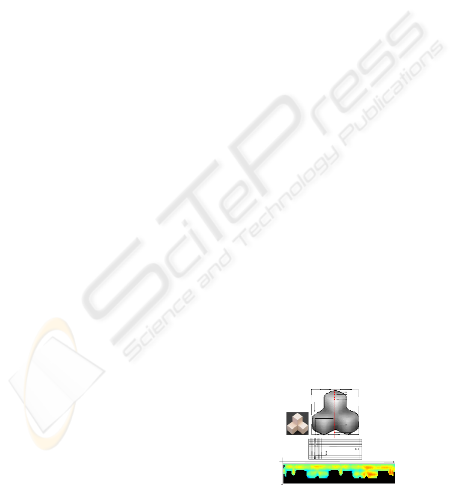
Figure 3: Viewpoints defined by the tessellated sphere and
depth images synthetically generated (left). Whole BGI-
BS model (right).
In practice a factor f
mm-pixel
turns into pixels.
f
j
iH
Z
,
∇
mm-pixel
is maintained whatever scene we work with.
This change makes the DGI-BS representation
invariant to camera-scene distance.
2.2 The Whole DGI-BS Model
The whole DGI-BS model of an object is an image
that comprises k DGI-BS representations from k
different viewpoints. In practice we use a
synthesized high-resolution geometric model of the
object to obtain the depth images. The viewpoints
are defined by the nodes of a tessellated sphere that
contains the model of the object. Each node N
defines a viewpoint ON, O being the centre of the
sphere (Fig. 3 left), from which the DGI-BS
representation is generated. Thus, a whole DGI-BS
model consists of an image of
dimension . We have duplicated
dimension p in order to carry out an efficient partial-
whole DGI-BS matching. Fig. 3 shows the whole
DGI-BS model for one object. Note that this is a
single image smaller than 1 mega pixel (1600x400
pixels in this case) that synthesizes the surface
information of the complete object.
)*2),(( ptk ∗
2.3 DGI-BS with Occlusion
Let us suppose that an object is occluded by others
in a complex scene. In this case DGI-BS can be
obtained if the silhouette corresponding to the non-
occluded part of the object is obtained in advance.
We call this “real silhouette”. Therefore, it is
necessary to carry out a preliminary range image
processing consisting of two phases: segmentation
and real silhouettes labelling. Since this paper is
focused on present the DGI-BS and due to length
limitations only a brief reference of these issues is
given. More details can be found in (Merchán, 2002)
and (Adán, 2005).
Segmentation means that the scene splits in a set
of disjointed surface portions belonging to the
several objects. Segmentation can be accomplished
by discovering depth discontinuity and separating
set of points 3D in the range image. We have used
the technique of Merchán et al. (Merchán, 2002)
which is based on establishing a set of suitable data
exploration directions to perform a distributed
segmentation. Since this issue is not the matter of
this paper, from now on we will assume that the
range and the intensity image are segmented in
advance.
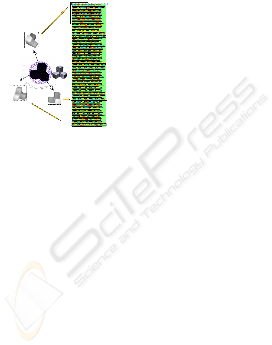
Concerning the real silhouettes labelling, a
generic silhouette H, corresponding to a segmented
portion of the scene, is divided up into smaller parts
which are classified as real or false silhouettes. To
do that, we consider two steps:
I. Define H as a sequence of isolated and
connected parts. A part is isolated if all their points
are far enough from every other contour in the image
and connected if it is very close to another part
belonging to another contour. In conclusion, this
step finds the parts of the contours that are in contact
and those that are not.
II. Define H as a sequence of real (R) and false
parts (F). The goal is to find which parts occlude to
others (R) and which ones are occluded parts (F).
The set of connected parts must be classified as real
or false. Using Z (depth image) we compare the
mean depths for each pair of associated connected
parts (belonging to the contours H and H’) and we
classify it. After comparing all connected pairs of H,
the real silhouettes are finally obtained. See figure 4.
After carrying out the real silhouette labelling
process we can obtain the DGI-BS representation for
every segmented surface of the scene. In the case of
an occluded object, we build DGI-BS only for the
longest real silhouette of H. In practice, one or two
real parts (which correspond to one and two
occlusions) are expected. Of course, cases with more
occlusions are possible but in any case the largest
real part must be at least 30% of H. Otherwise very
little information of the object would be available.
Note that in occlusions circumstances DGI-BS is
a
'pt
×
sub-matrix of the non-occluded DGI-BS
DEPTH GRADIENT IMAGE BASED ON SILHOUETTE - A Solution for Reconstruction of Scenes in 3D Environments
115
version. Since a close viewpoint is available in the
whole DGI-BS model, this property can be easily
verified. Fig. 5 illustrates an example of this
property. Now dimension p’<p but dimension t is
image of the object is not complete more sampled
points fall outside the object. That is why a few
more number of black pixels appears in it.
3 SURFACE CORRESPONDENCE
THROUGH DGI-BS
The whole DGI-BS model gives complete
information of an object. Consider to
be a reference system O being the geometric
centroid of the object, v being a viewpoint of the
scene defined by the polar coordinates (ρ,θ,ϕ) and φ
being the camera swing angle. When a surface
portion Θ is segmented in a complex scene, DGI-
BS
),,,( ZYXO
Θ
can be searched in the whole model of the
object. Thus, two coordinates (k
Θ
, p
Θ
) in the whole
DGI-BS space can be determined in this matching
process: the best view (index k) and the best fitting
point (index p).
Figure 4: Scene C: range image processing: segmentation
and real silhouettes labelling (R=Real and F=false
silhouette).
Figure 5: DGI-BS representation of a non-occluded object
(above) and DGI-BS representation of the same object
under occlusion circumstances placed in the best matching
position (below).
Now we will present the sequence of steps in the
surface correspondence algorithm.
The segment is projected from camera viewpoint
and the depth image Z
Θ
and its silhouette H
Θ
are
obtained. After that, the real part of H
Θ
is extracted
according to the procedure explained in section 2.3.
If there are several real parts of the silhouette the
longest one is chosen and the corresponding DGI-
BS
Θ
representation is generated. Then a scene-model
matching in the DGI-BS space is carried out and two
coordinates in the DGI-BS space are determined.
For a database with n objects we have n candidate
views, one for each object of the database, with their
respective n associated fitting points. For every pair
of index (k, p)
m
, m=1…n, a mean square
error, is defined for each candidate.
)(me
BSDGI −
Note that the surface correspondence is based on
both surface and contour information. Surface
information is supplied by DGI-BS representation
and contour information is intrinsic to the DGI-BS
definition itself. However DGI-BS representation
could be ambiguous, especially on flat surfaces and
hard occlusion cases. Consequently, to make the
surface correspondence algorithm more efficient, we
have added extrinsic information of the silhouette.
This information consists of the Function of Angles
(FA). FA contains the tangent angle for every pixel
of real part of the silhouette. This is a typical slope
representation of a contour.
Like , for every pair of index (k, p)
)(me
BSDGI −
m
,
m=1…n, FA matching error, , is calculated.
Finally, by minimizing the error the
best surface correspondence is finally selected. On
the other hand, a sorted list of candidates is stored
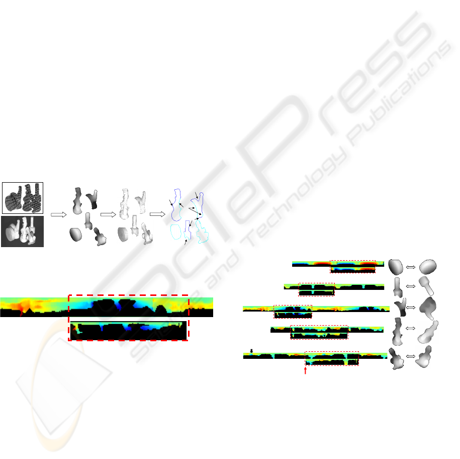
for further purposes. Fig. 6 shows the best DGI-BS
matching for several segments of scene C. It can be
seen the DGI-BS of the best view (index k) and the
DGI-BS of the segments at the fitting position
(index p). The scene-model surface correspondences
are shown on the right
.
)(me
FA
FABSDGI
eee .
−
=
Scene Image
Segmentation
Scene
2D
Segmentation
Silhouette
labelling
F
R
R
R
R
F
R
Scene
Model
Fitting point
(index p)
Best view in DGI-BS of the candidate model (index k)
Figure 6: DGI-BS matching for several objects of the
scene C.
4 CORRESPONDENCE
VERIFICATION THROUGH
REGISTRATION
Let us assume that DGI-BS
M
is the best candidate
obtained in the correspondence phase. Note that
when the DGI-BS matching problem is solved a
ICINCO 2006 - ROBOTICS AND AUTOMATION
116
point to point correspondence is established in the
depth images Z
Θ
and Z
M
and, consequently, the same
point to point correspondence is maintained for the
corresponding 3D points C
Θ
and C
M
. Thus a coarse
transformation T
*
between C
Θ
and C
M
is easily
calculated. After that we compute a refined
transformation that definitively aligns the two
surfaces in a common coordinate system. Thus,
through the error yielded by a registration technique,
we can analyse the goodness of the coarse
transformation T
*
and evaluate the validity of the
DGI-BS matching.
We have used the well known ICP registration
technique. ICP algorithm has been widely studied
since the original version (Besl, 1992) and many
researchers have proposed a multitude of variants
throughout the 90’s (Rusinkiewicz, 2001). In this
work, we have used the k-d tree algorithm and the
point-to-point minimization (Horn, 1988).
The goodness of the registration and, indirectly,
the recognition/pose result is validated taking into
account the value of e
ICP
. In other words, we want to
establish if the candidate chosen in the
correspondence phase was right or wrong.
In order to calculate a threshold value for e
ICP
, an
off-line ICP process is performed over a set of
random viewpoints for all synthetic models of the
database. As a result of that an e
ICP
histogram is
obtained and a normal distribution is fitted to it.
Finally we define:
ICP
eZSe
ICP
−=
max
(4)
where Z is the value of the normal distribution
corresponding to the 100 percentile (Z=3,99), S
ICP
is
the standard deviation and
ICP
e
is the mean of the
distribution.
After carrying out the surface correspondence and
alignment phases for the best candidate, if
we consider that the surface
correspondence has been wrong. In this case, the
next candidate in the list is taken and a new e
max
ee
ICP
>
ICP
is
computed and evaluated again (see figure 7)
.
Model M1st
Model L2nd
Model V3rd
..
..
Model Gn-th
DGI-BS point-to-point
correspondence
3D point-to-point
correspondence
Coarse transformation → T
*
ICP → T
e
ICP
<e
max
Recognition and pose
Figure 7: Correspondence verification and registration.
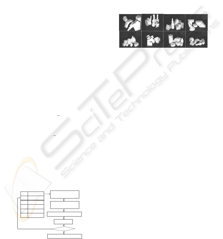
5 EXPERIMENTAL RESULTS
We have tested our algorithm on a set of 20 scenes
captured with a Gray Range Finder sensor which
provides coordinates (x,y,z) of the points of the
scene. The depth map of the scene is obtained
through the camera and sensor calibrations. Scenes
are composed of several objects that are posed with
no restrictions and with the same texture (Fig. 8).
Dimension of the scene is 30x30 cm and the sensor-
scene distance is 120 cm. Our database is made up
of 27 objects.
A
E
F
G
H
A
D
C
B
1
2
3
4
5
1
2
3
4
1
2
3
4
5
1
2
3
4
5
1
2
3
4
5
1
2
3
4
1
2
3
4
5
1
2
3
4
5
Figure 8: Some of the scenes used in our experimentation.
The values selected for the parameters to create
the whole DGI-BS representation are:
• Factor f
mm-pixel
=10 pixels/cm, so depth image
dimension is about 120x120 pixels. Likewise,
depth images of segmented objects are converted
using the same scale factor. This means that the
correspondence method is independent of the
object-camera distance.
• The whole representations have been obtained by
using a tessellated sphere of 80 nodes (
80
=
k
).
We have also used tessellated spheres with more
resolution (320 nodes) but the results do not
improve meaningfully and the computational time
increases a lot.
• Number of sampled pixels in the 2D normal
direction
20
=
t
and distance in pixels between
samples
5
=
s , so the penetration inside the depth
image is 100 pixels.
Figure 9 illustrates the recognition/pose process of
occluded objects in scene F. The surface portions
obtained after the segmentation phase appears on the
left. In this case there are three portions 1, 2 and 4
that are occluded. Their corresponding depth images
are shown and the real silhouettes are marked onto
them. Below we present the result of the scene-
model matching in the DGI-BS space for the best
candidate. The best view (index k) at the best fitting
position (index p) can be seen for all them. Finally,
the depth image of the associated model is shown of
the right. On the right we show the alignment and
the spatial position of the models in the scene. We
can see the 3D points of the scene and the
registration result of segments. The corresponding
DEPTH GRADIENT IMAGE BASED ON SILHOUETTE - A Solution for Reconstruction of Scenes in 3D Environments
117
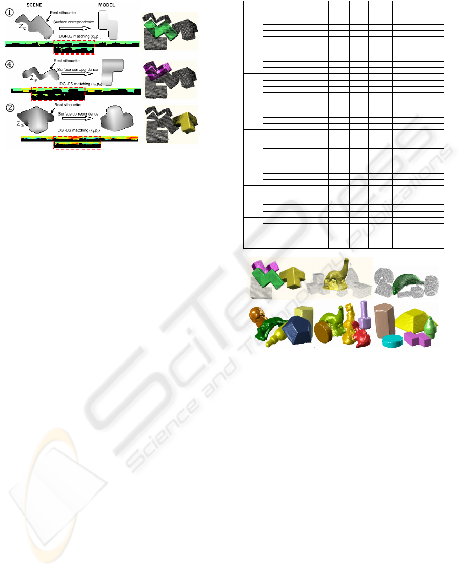
rendered models are superimposed onto the scene.
Figure 9: Example of surface correspondence (left) and
alignment of occluded surfaces (right).
Table I shows a summary of the results for all
objects of the scenes A to H. 60,5% of the objects
were occluded. We have included some important
information like errors in the segmentation phase
(‘seg. error’) and noise in the range image (‘noise’).
A segmentation error would imply that two objects
were labelled as one object or that an object was
segmented in several segments. The first case
corresponds to two surfaces that are joined and
where there are not depth discontinuities between
both surfaces. This is quite uncommon case but of
course the approach would fail. The second case
occurs in self-occlusion circumstances but the
method works as in a single occlusion case except
that the surface portions will be smaller than in non-
occlusions cases. In all cases the scenes were
segmented in their constituent parts achieving 100%
of effectiveness. On the other hand, the noise in the
range is due to shades or highlighting regions.
Coordinate k, which corresponds to the best
matching view, is evaluated as right (R) or erroneous
(E) in the column ‘view’. This is a visual evaluation
that report us the total percentage of failures in the
DGI-BS matching phase. In our experimentation we
obtained 2,6 % of failures in this phase (1/38).
The column labelled ‘candidate’ means the first
candidate of the list that verifies
max
and
that finally is chosen as candidate. In 63,2 % of the
cases the first candidate was the first of the list and
the average position was 2. Finally, the last column
gives information about the ICP algorithm itself
showing the number of iterations in the ICP
algorithm. In summary we can conclude that the
approach is highly effective (97,4%).
ee
ICP
<
Figure 10 shows examples of pose for multi-
occluded objects (scenes E, F and H) and the
complete reconstruction of the scenes A, B and G.
Table I.
SCENE Object Occlusion
Seg.
error
Noise View Candidate e
ICP
Iterations
ICP
1
Yes No No R 9º
0.1108 35
2
Yes No No R 1º
0.1187 41
3
No No Yes R 1º
0.1237 43
4
Yes No Yes R 1º
0.1244 18
A
5
Yes No No R 8º
0.0836 51
1
No No No R 1º
0.0693 35
2
Yes No No R 1º
0.0997 21
3
Yes No No R 1º
0.0924 45
4
Yes No Yes R 5º
0.1163 36
B
5
No No No R 1º
0.0800 35
1
Yes No No E 2º
0.1593 79
2
Yes No No R 2º
0.1339 18
3
Yes No No R 6º
0.1979 30
4
No No No R 1º
0.1393 22
C
5
No No Yes R 3º
0.1427 25
1
No No Yes R 1º
0.1640 29
2
No No No R 1º
0.1545 23
3
Yes No No R 1º
0.1617 38
D
4
Yes No No R 3º
0.1559 35
1
Yes No No R 1º
0.1235 32
2
No No No R 1º
0.1337 18
3
No No Yes R 2º
0.1421 44
4
Yes No No R 1º
0.1515 47
E
5
No No Yes R 1º
0.1145 34
1
Yes No No R 1º
0.1328 24
2
Yes No No R 3º
0.0090 35
3
No No No R 1º
0.1000 53
F
4
Yes No Yes R 1º
0.0939 45
1
No No No R 1º
0.1154 35
2
Yes No Yes R 1º
0.1359 12
3
Yes No No R 1º
0.1353 28
4
Yes No No R 1º
0.1526 11
G
5
No No Yes R 1º
0.1252 39
1
Yes No No R 3º
0.1227 67
2
Yes No No R 2º
0.1953 46
3
Yes No Yes R 4º
0.1676 78
4
No No Yes R 2º
0.1381 19
H
5
No No No R 1º
0.1335 50
Figure 10: Example of recognition and pose of multi-
occluded objects (above) and rendered representation of
the complete scene (below).
6 CONCLUSIONS
This work deals with the problem of correspondence
and registration of surfaces by using a strategy that
synthesizes both surface and shape information in
3D scenes with occlusions. The method provides at
the same time recognition and pose of segments of
the scene. This work is part of a robot intelligent
manipulation project.
DGI-BS (Depth Gradient Image Based on
Silhouette) representation is a complete and discrete
representation suitable in 3D environments.
Moreover, DGI-BS representation can be applied to
obtain a complete model as well as a partial model
of an object. This property allows us to use it in
complex scenes with multi-occlusion.
Recognitions and pose problems are solved by
using a simple matching algorithm in the DGI-BS
ICINCO 2006 - ROBOTICS AND AUTOMATION
118

space that yields a coarse transformation.
Afterwards, registration is sorted out by computing
ICP alignment of corresponded surfaces.
We are currently working on the detection and
correction of wrong correspondences. Part of these
problems may be due to noise and errors in 3D data
acquisition stages.
ACKNOWLEDGEMENTS
This work has been supported by the Spanish
projects PBI05-028 JCCLM and DPI2002-03999-
C02
REFERENCES
Antonio Adán and Miguel Adán, 2004. A flexible
similarity measure for 3D shapes recognition. In IEEE
TPMI, 26(11), 1507–1520.
A. Adán, P. Merchán, S. Salamanca, A. Vázquez , M.
Adán, C. Cerrada, 2005.Objects Layout Graph for 3D
Complex Scenes. In Proc. of ICIP’05.
A. Ashbrook, R. Fisher, N. Werghi, C. Robertson, 1998.
Aligning arbitrary surfaces using pairwise geometric
histograms. In Proc. Noblesse Workshop on No-linear
Model Based Image Analysis, 103-108.
Alferez, R., Wang,Y.F., 1999.Geometric and illumination
invariants for object recognition. In IEEE TPAMI 21,
505-535
Bamieh, B., De Figuereido, R.J.P., 1986. A general
moment-invariants/attributed graph method for three-
dimensional object recognition from single image. In
IEEE T. Rob. Aut., RA-2, 31-41
Besl, P. and McKay, N., 1992. A method for registration
of 3-D shapes. In IEEE TPAMI, 14 (2), 239-256.
R. Campbell, P. J. Flynn, 2002. Recognition of Free-Form
Objects in Dense Range Data Using Local Features. In
16th International Conference on Pattern Recognition.
C.M. Cyr and B.B. Kimia, 2004. A similarity-based
aspect-graph approach to 3D object recognition. In Int.
Journal of Computer Vision, 57(1), 5–22.
Ching S. Chua, Ray Jarvis, 1997. Point signatures: A new
representation for 3D object recognition. In
International J. of Comp. Vision, 25(1), 63–85.
Horn, B., 1988. Closed-Form Solution of absolute
orientation using orthonormal matrices. In Journal of
the Optical Society A. 5 (7).
Andrew E. Johnson and Martial Hebert. 1999. Using spin
images for efficient object recognition in cluttered 3d
scenes. In IEEE TPAMI, 21(5), 433–449.
Lee, J.D., 2000. A new scheme for planar shape
recognition using wavelets. In Comp. Mach. Appl. 39
201-216
Merchán, P., Adán, A., Salamanca, S., Cerrada, C., 2002.
3D complex scenes segmentation from a single range
image using virtual exploration. In LNAI, 2527, 923–
932.
Mokhararian, F. S., 1997. Silhouette-based occluded
object recognition through curvature scale space. In
Mach. Vis. Appl. 10, 87-97
B.M. Planitz, A.J. Maeder, J.A. Williams, 2005. The
correspondence framework for 3D surface matching
algorithms. In Comp. Vis. Image Underst. 97,347-383.
Roh, K.C., Kweon, I. S., 2000. 3-D object recognition
using a new invariant relationship by single view. In
Pattern Recognition 33, 741-754.
Rothwell, C.A., Zisserman, A., Forsyth, D.A., Mundy,
J.L., 1995. Planar object recognition using projective
shape representation. In Int. J. Com. Vision 12, 57-59
Rusinkiewicz, S., and Levoy, M., 2001. Efficient variant
of the ICP algorithm. In Proc. of 3DIM’01. 145-152.
Trazegnies,C.,Urdiales,C., Bandera,A., Sandoval,F., 2003.
3D object recognition based on curvature information
of planar views. In Pattern Rec. 36, 2571-2584.
Xinguo Liu, Robin Sun, Sing Bing Kang, and Heung-
Yeung Shum, 2003. Directional histogram for three-
dimensional shape similarity. In Proc. of the IEEE
Conference on CVPR, I, 813–820,.
Xu, D., Xu,W., 2005. Description and Recognition of
object contours using arc length and tangent
orientation. In Pattern Rec. Letters 26, 855-864
Sameh Yamany and Aly Farag, 2002.Surfacing signatures:
An orientation independent free-form surface
representation scheme for the purpose of objects
registration and matching. In IEEE TPAMI,
24(8),1105–1120.
Zabulis, X., Sporring, J., Orphanoudakis, S.C., 2005.
Perceptually relevant and piecewise linear matching of
silhouettes.In Pattern Recognition 38, 75-93
Zahn, C.T., Roskies, R.C., 1972. Fourier descriptors for
plane closed curve. In IEEE T. Comp. 21,195-281
Zhang, Z., 1994. Iterative point matching for registration
of free-form curves and surfaces. In International
Journal of Computer Vision, 13 (2), 119-152.
Zhang, 1999. Harmonic Shape Images: A 3D free form
representation and its applications in surface matching.
In PhD thesis CMU. Pennsylvania. USA.
DEPTH GRADIENT IMAGE BASED ON SILHOUETTE - A Solution for Reconstruction of Scenes in 3D Environments
119
