
Formal Specification of Real-Time Systems by
Transformation of UML-RT Design Models
K. Benghazi Akhlaki
1
, M. I. Capel Tuñon
1
, J. A. Holgado Terriza
1
,
L. E. Mendoza Morales
2
1
Departamento de Lenguajes y Sistemas Informáticos, ETSI Informática, Campus
Aynadamar, Universidad de Granada, 18071 Granada, Spain
2
Departamento de Procesos y Sistemas, Edificio de Matemáticas y Sistemas, Universidad
Simón Bolívar, Apartado 89000, Baruta, Caracas, 1080-A, Venezuela
Abstract. We are motivated to complement our methodology by integrating
collaboration diagrams to facilitate the specification of capsules in UML-RT
design models. An improved systematic transformation method to derive a cor-
rect and complete formal system specification of real-time systems is estab-
lished. This article aims at integrating temporal requirements in the design
stage of the life cycle of a real-time system, so that scheduling and dependabil-
ity analysis can be performed at this stage. The application of CSP+T process
algebra to carry out a systematic transformation from a UML-RT model of a
well known manufacturing-industry paradigmatic case, the “Production-Cell”,
is also presented.
1 Introduction
UML (Unified Modelling Language) [1], has become one of the most widely used
standards for modelling and designing the industrial software systems, essentially,
because it is a semi-formal notation relatively easy to use and well supported by tools.
An extension to UML, named UML-RT [2], has been defined on the basis of ROOM
language [3], an architectural definition language specifically developed for model-
ling complex real-time software systems. However, the lack of formal semantics for
UML-RT makes it very difficult to assure the correctness of a hard real-time and
critical system under development
Formal methods [4] have demonstrated to be effectively applicable in the industrial
development of real-time systems, and they are advocated as a means of providing a
higher level of confidence in the correct functioning of software. Nevertheless, they
have not the same acceptance in the industry as semi-formal ones, such as the case of
UML. The problem is that formal methods are hard to master and too expensive to be
used extensively during the entire software development process [5].
On the other hand, it is well known that the combination of UML modelling nota-
tion with formal specification languages may take advantage of their benefits and
overcome its deficiencies if the integration scheme between formal constructs and
Benghazi Akhlaki K., I. Capel Tuñon M., A. Holgado Terriza J. and E. Mendoza Morales L. (2006).
Formal Specification of Real-Time Systems by Transformation of UML-RT Design Models.
In Proceedings of the 4th International Workshop on Modelling, Simulation, Verification and Validation of Enterprise Information Systems, pages 16-25
DOI: 10.5220/0002503200160025
Copyright
c
SciTePress

UML analysis entities is well performed.
In a previous work [6], we have presented a software specification method that
combines UML-RT and the CSP+T formal specification language. The method is
based on an initial UML-RT model of the system under development, which uses
extended UML State and class diagrams to model the behaviour, timing and architec-
tural aspects of the system. Then, the UML model is mapped into CSP syntactical
terms by applying a set of transformation rules, which permits to derive a formal
system specification of a target system.
Typically, the complete specification of the structure of a complex real-time sys-
tem is obtained through a combination of class and collaboration diagrams [7]. For
this reason, we are now motivated to complement our previously proposed procedure
with collaboration diagrams, to obtain a more complete and modifiable system speci-
fication of real-time systems. Similar approaches have been proposed in other arti-
cles, for instance, [8] maps UML-RT capsules to the formal language Circus [9]. Our
approach differs from the aforementioned in that it integrates the specification of
timing properties, and gives a complete view of the system behaviour. It can therefore
be said that the specification of RTS from a global view (i.e., including behavioural,
static and timing aspects) becomes feasible in a flexible and easy way. As to show its
applicability, we have used the method to carry out the specification, including real-
time constraints, of two basic components of the “Production Cell”, which is a well
known manufacturing-industry paradigmatic case. The rest of this paper is structured
as follows: section 2 provides an overview of the UML-RT, section 3 describes the
CSP+T Language and section 4 explains the system specification method proposed
here. In Section 5, we present the specification of central elements of the Production
Cell components (the robot and the Press). Finally, some conclusions are drawn and
the references are listed.
2 UML-RT
UML-RT extends the basic UML analysis entities with constructs to facilitate the
design of complex embedded real-time software systems. The origin of the UML-RT
modelling notation is the real-time specific modelling language ROOM, which has
been modified to follow the UML standardized framework. The language focuses
primarily on the specification of the architecture of software systems, i.e., their major
components, the externally visible properties of these, and the communication be-
tween them. The importance of the software architecture definition in the develop-
ment cycle is argued by considering that decisions made during the architectural de-
sign will have a very important impact on the later system design, being also this
phase that can profit the most from a good modelling language.
UML-RT adds four new building blocks to the standard UML (see Fig. 1):
Capsules. A capsule is a stereotype of a UML class entity with some specific fea-
tures. Capsules are constructs for isolating functionality with a very clearly defined
interface. Each capsule operates according to a state diagram, which responds to
events and generates actions through its ports.
- Ports. A port represents an interaction point between a capsule and its environ-
ment. They convey signals between the environment and the capsule. The port nota-
17

tion is shown as a small hollow square symbol. If the port symbol is placed overlap-
ping the boundary of the rectangle symbol, it denotes a public visibility. If the port is
shown inside the rectangle symbol, then the port is hidden and its visibility is private.
When viewed from within the capsule: two types of ports are defined: relay and end
ports. A relay port transmits signals between a capsule and its subcapsules. An end
port is a component that represents the transmission of signals between the capsule
and its Statechart.
- Protocols. A protocol captures a set of valid communications (signal exchanges)
between two or more capsules.
- Connectors. A connector is an abstraction of a message-passing channel that
connects two or more ports. Each connector is typed by a protocol that defines the
possible interactions that can take place across that connector.
+ / P1
: Pcole1
+ / P1
: Pcole1
+ / P2
: Pcole1
+ / P2
: Pcole1
+ / P3
: External
+ / P3
: External
# / p4
: Pcole2
# / p4
: Pcole2
+ / p5
: Pcole2
+ / p5
: Pcole2
Fig. 1. Port notation - collaboration diagram.
3 CSP+T
CSP+T [10] extends the well-known CSP [11] [12] (Communicating Sequential Proc-
esses), formal specification language with timing primitives. CSP is an event based
notation primarily aimed at describing the sequencing of events within process behav-
iour and the synchronisation (or communication) between processes. CSP+T, which
is a new real-time specification language, extends CSP, by introducing a new set of
constructs, to allow the description of complex event timings from within a single
sequential process, thereby providing a valuable insight into the behavioural specifi-
cation of real-time systems.
The syntax of CSP+T, which is a superset of the CSP one, has been adapted to our
method. The differences between the two formal specification languages are de-
scribed as follows:
- Every process P defines its own set of communication symbols, termed the com-
munication alphabet α(P). These communications represent the events that process P
receives from its environment (constituted of all the other processes in the system) or
that occur internally, such as the event τ which is not externally visible. External
events can be understood as the pure synchronization between an asynchronous proc-
ess and its environment. Any type of event causes a state change of the process in
which it is observed.
- The communication interface Comm_act(P) of a given process P contains all the
CSP-like communications, i.e. the synchronous, one-to-one, communications between
parallel processes, in which process P can engage and it also includes the alphabet
α(P), representing signals and events occurring in P. Therefore, the communications
of process P are given by the set Comm_act(P)= (Interface(P)
∪ α(P)).
18

- A new operator, ∗ (star), is introduced in the programming notation to denote
process instantiation. An instance of a process term must be created before it can
execute. This event is unique in the system since it represents the origin of a global
time at which processes can start their execution. As an example, let us consider a
process P that initially can only engage in the event a. In CSP, this process would be
denoted as: P = a →STOP, but it must be instantiated before being executed in
CSP+T. Given P', the timed version of P, which is instantiated at time 1, where s is a
time stamp associated to the abstract communication a, the specification of P' be-
comes,
P'= 1.∗ → s.a → STOP where s ∈[1, ∞[
It should be noted that event a occurs only once in the interval.
− A new event operator >< is introduced to be used jointly with a “marker vari-
able” to record the time instant at which the event occurs. ev>< v means that the time
at which ev is observed during a process execution is in the marker variable v. The
value of time stamps is taken from the set of positive real numbers, so that successive
events form a non-decreasing monotonic sequence. As several successive events can
instantiate the same variable at different times, if we specify the process P as follows
:
P= 1.∗ → a >< var → STOP
- For each process execution, the marker variable var will record the correspond-
ing time value at which event a occurred, and it will always satisfy var > 1.
The scope of marker variables is strictly limited to one sequential process. They
cannot be referenced or accessed in any other way within a concurrent composition of
processes.
- Each marker event is usually associated with a time interval, which is called its
“event-enabling” interval and represents the period of time over which the event is
continuously available to the process and its environment. During this interval, the
event can be detected, then provoking an instantaneous change of state either in the
process or in the environment. The initial times for intervals are relative to a preced-
ing event or to a marker variable, which is instantiated during current process execu-
tion. A process is considered to be the STOP process if it cannot engage in the marker
event or in an alternative event during the enabling interval. Let us suppose, for in-
stance, that there is a process P, a process which can only engage in event a, which
can only occur between 1 and 2 units of time from the process instantiation time (the
preceding event), recording in the marker variable v the time at which the event a
occurred. The specification of this process is therefore:
P= 0.∗ → [1, 2].a >< v → STOP
After the process execution, the value of the marker variable satisfies the inequal-
ity 1 ≤ v ≤ 2. The enabling interval can be defined in a more compact way by using
the function I, I (T,v), where v is the marker variable that records the time instant at
which the preceding event occurred, and T defines the duration of the time interval
starting at the time instant stored in v. An example is:
P = 1.∗ → a >< v → I(3,v).c → d → STOP ,
in which the event c can occur at least three time units after the process P engages in
the event a.
If the marker variable does not appear in the signature of function I, the enabling
interval is relative to the previous marker variable in the scope of the process, other-
wise the enabling interval for that process is considered the default interval [0, ∞].
19

The times for events are absolute and the times for intervals are relative to the preced-
ing time stored in marker variable.
- The semantics of the parallel composition of two processes with enabling inter-
vals which must be synchronized depends on whether the values of these intervals are
identical, partially overlapping or disjoint. In the first case, the processes synchronize
on the common initial events, as established in CSP communication semantics, i.e.,
given
P= E1.Q and R= E2.S, then
P||Q ≠ STOP iff α(Q)∩ α(S)≠Ø ∧ E1∩E2≠Ø
In the case of disjoint enabling intervals (E1
∩
E2 = Ø), the parallel composition of
processes behaves as the STOP process.
4 Formal Specification and Transformation Methodology from
UML-RT
To manage the complexity of real-time systems, a bottom-up, compositional strategy
is proposed here. The methodological procedure consists of first dividing the target
system into a set of subsystems and then considering the architecture of the entire
system model as a net of capsules connected by ports that intercommunicate accord-
ing to a previously defined protocol. For instance, the system Sys in Fig. 2.a has been
divided into two subsystems (Capsules).
- The entire system architecture is modelled using a Class Diagram, which repre-
sents each system components by a UML capsules, and their interactions are defined
by a set of operations (signals) encapsulated in protocols. In Fig. 2a the signals e
1
, e
2
of the protocol PROT-AB are the events exchanged between the capsules Caps A and
Caps B.
- Subsystems internal structure is described by a Collaboration Diagram, which
identifies the components of the lower level subsystems and how they are connected.
In Fig. 2b Caps A is composed of the subcapsules X and Y that are connected
through the ports Px and Py. Caps A and caps B communicate through the ports Pa
and Pb which convey "Prot_AB" signals between these capsules.
- Subsystems behaviour and timing requirements are modelled using the extended
State Diagram (UML-SD), established in a previous work [6], which extends the
standard UML-SD with new constructs inspired on CSP+T syntax to capture timing
properties. The extension consists of an annotation for describing timing events, ena-
bling intervals assigned to events to restrict their time execution, and a new type of
transition labelled with a special event, called timeout. Timeout triggers a state
change to a Skip state. In Fig. 2c, we mark the occurrence of the events e
1
by the
annotation t
e1
= gettime (), and we restrict the execution of the event e
2
to an interval I
by the annotation I.e
2
.
To overcome the lack of formal semantics of UML and to ease the usually diffi-
cult applications of formal methods, we systematically derive the formal specifica-
tion in terms of CSP+T from the UML-RT models, by applying a set of rules already
established in previous works [6] [13].
20

+ / Pa
: P rot_A B
+ / Pa
: P rot_A B
+ / Pb
: Prot_AB~
+ / Pb
: Prot_AB~
CapsB
XY
Px
Py
CapsA
S1
S2
S3
Start
ev1
ev2
ev
^ev3
Start
Tev1= gettime()
ev1
ev2
ev
^ev3
I.
Sb1
Sb2
Initia lInitia l
ev3ev3
evev
Sy1 Sy2
In i tia lIn i tia l
eyey
evyevy
Fig 2.a
Fig 2.c
Fig 2.b
Modelling
System
Architecture
Modelling
Internal
Structure
Modelling
Behaviour
And
Timing
C2
C1
Sys
<<Capsule>>
CapsA
+ / Pa : Prot_AB
<<Capsule>>
Ca psB
+ / Pb : Prot_AB~
<<Capsule>>
Prot_AB
<<Protocol>>
ev1 ()
ev2 ()
ev3 ()
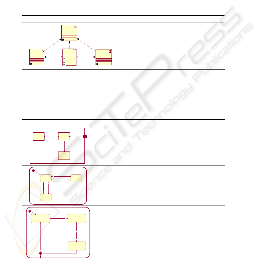
Fig. 2. Real-Time system Model
The complete system specification is obtained by the composition of a set of proc-
esses that specify subcapsules by using CSP operators, such as the parallel composi-
tion one. By the example shown in Fig.2, we can describe the compositional con-
struction of a system specification. We first specify the entire architecture by map-
ping the class diagram (Fig. 2.a) into CSP process terms as discussed in [6]:
Sys = (CapsA||CapsB)\{ev1, ev2, ev3}.
Then, we specify the internal structure of each capsule on the class diagram by
mapping the collaboration diagram into CSP processes, according to a procedure
established in [13]. The transformation of CapsA in a collaboration diagram (Fig. 2.b)
yields the next CSP syntactical terms:
X = X [Px → C1], Y = Y[Py → C1,P’y → C2]
CapsA = (X || Y) \ C1
The specification technique is compositional. The specification of the dynamic
behaviour of a capsule can therefore be obtained by composing the individual sub-
capsule behaviour specifications. From the transformation of the SD that represents
the behaviour of capsule X and capsule Y (Fig. 2.c), we obtain:
X= Start → S1
21
S1= ev1><t
ev1
→ S2
S2= I(T, t
e1
).ev2 → S3
S3= ev3 → S1.
Y= Start → Sy1
Sy1= evy
→ Sy2
St2= ey → ST1.
The behaviour of CaspA is obtained by parallel composition of X and Y processes.
5 The Production Cell Case Study
The case study [14] presents a realistic industry-oriented problem, where safety re-
quirements play a significant role and can be met by the application of formal meth-
ods. The design activity of the Production Cell (PC) system is of manageable com-
plexity; thus, it allows us to experiment with several alternative designs before mak-
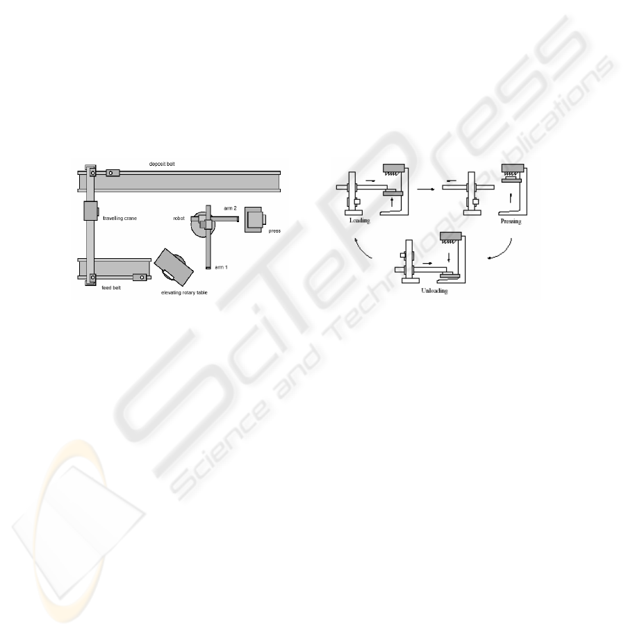
ing the decision to take a particular one. Fig. 3a shows a top view of the plant that
holds the PC.
3a. Top View of the plant 3b. Robot and Press
Fig. 3. Production Cell.
The model includes several machines that must be coordinated in order to forge
metal blanks. The machines process metal blanks at the greatest possible speed, and
at the same time, they must avoid dropping blanks to the floor or colliding to each
other. There is a conveyor belt that feeds blanks into a rotary table. The table rotates
and lifts the blanks so they can be picked up by the first robot arm. The robot has two
arms, one for feeding the press with blanks and the other for removing forged blanks
from the press. The robot is very efficient and it can simultaneously use an arm to
place a forged blank into the deposit belt and the other arm to convey a new blank to
the press.
We decide to model the central elements of the system: the press and the robot.
The robot task consists in taking metal blanks from the elevating rotary table to the
press and transporting forged plates from the press to the deposit belt. The task of the
press is to forge metal blanks. The above two components work simultaneously: the
mobile part of the press is initially in the middle position until the robot places a
blank into the press. After being loaded, the press starts moving upwards and presses
the blank until it becomes forged. It starts moving downwards to the unloading posi-
22
tion and finally the robot picks up the forged piece and the cycle starts again. Figure
3b graphically represents these steps.
To specify the system composed of the Robot and the Press components, we fol-
low the methodology described in the previous section. First, we decompose the sys-
tem into two principal components: Press and Robot, which can be separately mod-
elled as capsules in UML-RT notation.
The architecture of the system composed of the robot and the press is specified by
mapping the class diagram into CSP processes.
Table. 1. Model of the Robot and the Press interaction.
UML-RT Model Derived Specification on CSP+T terms
Robot
+ / Pr : Prot_RP
<<Capsule>>
Press
+ / Pp : Prot_RP~
<<Capsule>>
Prot_RP
forg e ()
PrsRdload ()
PrsRdunload ()
<<Protocol>>
+ / Pr+ / Pr
+ / Pp~+ / Pp~
Robot_Press
+ / Prp : Prot_RP
<<Capsule>>
/ robotR1 / robotR1
/ pressR1 / pressR 1
+ / Prp+ / Prp
Robot-Press = (Robot || Press) \
{forge, prsRdload, prsRdunload}
We model the behaviour and the internal structure of each capsule by using the ex-
tended UML state diagrams and collaboration diagrams, respectively. The application
of the set of rules proposed by the methodology allows us to derive system specifica-
tions in CSP+T terms, as it is shown in Tables 2 and 3.
Table. 2. Model and the derived specification of the behaviour and the internal structure of
Robot.
UML-RT Model Derived Specification on CSP+T terms
/ Arm1
/ RC
/ Arm2
+ / Pr
: Prot_RP
+ / P1
: C1
+ / P11
: C1~
+ / P1r
: Cr
+ / P12
: C2
+ / P2
: C2
C1
+ / Pr
: Prot_RP
/ Arm1
+ / P1
: C1
/ RC
+ / P11
: C1~
+ / P1r
: Cr
+ / P12
: C2
/ Arm2
+ / P2
: C2
C1
C2C2
CrCr
RC= RC [P12→ C2, P11 → C1, P1r → Cr]
Arm1= Arm1 [P1 → C1]
Arm2= = Arm2 [P2→ C2]
Robot = (RC || Arm1 || Arm2)\ C1,C2.
Stopped Extending
Retracting
In itia l
Retract
Retracted
Extended
Extend
In itia l
Retract
Retracted
Extended
Extend
Arm1= start → A1_stopped
A1_stopped= retract1 → Retracting1| ex-
tend1 → extending1
Retracting1= retracted1 → A1_stopped
Extending1= Extended1 → A1_Stopped
Waiting_for_Press_Unloading Waiting_for_Arm2_to_Extend
Waiting_for_Arm2_to_retrac t
t1
Initial
t2
t1
t1
t1t1
t1
Initial
t2
PRUnload^a2.Extend
a2extended^a2.Stop^a2.Load^retract
I.a2retracted^a2.Stop^ Press.unloaded
tpu=gettime()
tex=gettime()
tl oad=get time()
t-now>tpos2+T2
tretun=gettime()t1
t1
RC = Start → WFT
WPU= ((I(T
PR
,t
pos2
).PrUnload >< t
pr
→
A
2
.extend) → WA
2
2
1
) | I(T
TR
,t
pos1
) → time-
out
WA
2
E
2
=I(T
EX
,t
tr
).A
1
Extended><t
ex
→ A
1
.stop →
A
1
.load >< t
load
→ WA
1
R
1
WA
1
R
1
= I(T
ret
,t
load
).A
1
retracted><t
ret
→
A
1
.stop → Table.Unload → Turn(left) → CWW
...
23

Timing requirements are also taken into account to avoid a collision between two
components. For instance, the press may only move when no robot arm is positioned
inside it. So, we mark in the Robot SD the time when the arm1 is retracted ( back to
its rotating position ) by the annotation t
ret
= gettine(), and we restrict in the SD of
the press, the occurrence of the event move_up within an interval depending of t
ret
by
the annotation: I(T, t
ret
).
Table. 3. Model and the derived specification of the behaviour and the internal structure of
Press.
UML-RT Model Derived Specification on CSP+T terms
/ Plant / PC
+ / Pp
: Prot_RP~
+ / Ppr
: Cpp~
+ / Ppc
: Prot_RP~
+ / P1p
: Cpp
+ / Pp
: Prot_RP~
/ Plant
+ / Ppr
: Cpp~
/ PC
+ / Ppc
: Prot_RP~
+ / P1p
: Cpp
CpCp
CppCpp
PLANT = Plant[Ppr → Cpp]
PC= PC[Ppc → Cpp, P1p → Cp ]
Press = (PLANT || PC) \ Cpp
Loading Pressing
Unloading
Initia l
Moves_up
Moves_up
Moves_down
Initia l
Moves_up
Moves_up
Moves_down
I(now+T1.load).
Press_top^
I(now+T1.load).
PC = Start → Loading
Loading= forge → timeout → Pressing
Pressing= presstop → moves(down) →
Unloading
Unloading= unloaded → timeout →
moves(up)
At_Middle
Stop
Going_Up
Up
Going_D ow n
Initial
Moves_Stop
Moves_Up
Press_Top
Moves_Down
Press_Bottom
Press_middle
Initial
Moves_Stop
Moves_Up
Press_Top
Moves_Down
Press_Bottom
Press_middle
tup=gettime()
I.Press_Middle[Go_Middle]
PLANT= Start → Atmiddle
Atmiddle= moves (Stop) → Stopped
Stopped= moves(up)>< tup → Going_up
Going_up= I(Tmid, tup)&gomiddle → at-
middle | press(top) → up.
Up = moves(down) → Going_down
Going_down= press(bottom) → Stopped
6 Conclusions
In this work, we have complemented our methodological approach discussed in a
previous paper [6], with the integration of a collaboration diagram in order to capture
the internal structures of system components and their connections. These new con-
tribution strengthens our method, since we can systematically obtain a detailed sys-
tem specification from an initial UML model of high level of abstraction. We have
profited of the UML Object Oriented Paradigm to obtain a compositional technique
based on specifying each system capsules individually and subsequently composing
them by using CSP+T operators. Timing properties specification has been included in
the proposal, so that are taken into account to assure that real-time system properties
are fulfilled.
24

References
1. G. Booch, I. Jacobsen, and J. Rumbaugh. OMG Unified Modeling Language Specification,
March 2000. Available at www.omg.org/technology/documents/formal/unified modeling
language.htm.
2. Object Modeling Group: UML Profile for Schedulability, Performance, and Time Specifi-
cation, OMG Documents ptc/ 2003-03-02.
3. Selic. B, Gullekson, G., Ward, P.: Real-Time Object- Oriented Modeling. John Wiley &
Sons, Inc. (1994)
4. FormalSystems, FDR2.82 released. http://www.fsel.com. (2005)
5. Bowen, J. P.: Formal Methods in Safety-Critical Standards. Proc. 1993 Software Engineer-
ing Standards Symposium, IEEE Computer Society Brighton, UK(1993) 168-177
6. Capel, M.I., Benghazi, K., Holgado, J.A.: Combining the Description Features of UMLRT
and CSP+T Specifications Applied to a Complete Design of Real-Time Systems. Int. J. Inf.
Tech. 2 (2005) 137-146
7. Selic, B., Rumbaugh, J.: UML for modeling complex real-time systems. Technical report,
ObjectTime. (1998).
8. Ramos, R., Sampaio, A., Mota, A.: A semantics for UML-RT Active Classes via Mapping
into Circus. 7th IFIP WG 6.1 International Conference on Formal Methods for Open Object
Based Distributed Systems, Vol. 3535, (2005) 99-114.
9. XRCE (Xerox Research Centre Europe). Circus home page, 2002.
http://www.xrce.xerox.com/competencies/contextualcomputing/ circus.
10. Zic, J.J.: Timed constrained buffer specifications in CSP + T and timed CSP. ACM Trans-
action on Programming Languages and Systems, Vol. 16 (1994) 1661-1674
11. Hoare, C.A.R.: Communicating Sequential Processes, Prentice- Hall, Englewood Cliffs
(1985)
12.
Roscoe: The theory and practice of concurrency. Prentice Hall Prentice- Hall, Englewood
Cliffs (1997)
13.
Fisher, C. Olderog, E.R., Wehrheim, H.: A CSP view on UML-RT Structure diagrams.
Proceedings of the 4th International Conference on Integrated Fundamental Approaches to
Software Engineering. Springer-Verlag, Berlin Heidelberg New York (2001)
14. Lindert, Formal Development of reactive Systems: Case Study Production Cell. Lecture
Notes in Computer Science, Vol. 891. Springer-Verlag, Berlin Heidelberg New York
(1995) 415–438.
25
