
STABLE HAPTIC RESPONSE FOR COMPLEX INTERACTIONS
J. Hernantes, D. Borro
CEIT and TECNUN (University of Navarra), Manuel Lardizabal 15, 20018 San Sebastian, Spain
A. García-Alonso
University of Basque Country, Manuel Lardizabal 1, 20018 San Sebastian, Spain
Keywords: Haptic Rendering, Collision Response, Virtual Environment.
Abstract: Haptic technology is quite recent and therefore in many cases it is difficult to simulate real contacts or
interactions with a high sensation of realism. Collision response methods that calculate the force-feedback
tend to cause haptic instabilities when the normal direction changes abruptly. In consequence, collision or
contact events are often difficult to render properly in sharp corners by means of haptic devices. This paper
describes a collision response method which not only provides users with a stable force feedback, but also a
comfortable and convincing haptic interaction. The experimental results show that this approach leads to a
smoother force evolution which manages to avoid discontinuities and enhances the quality in the interaction
with corners.
1 INTRODUCTION
Humans are able to perceive the environment using
all their senses. Usually sight is the predominant
sense, although some of the other senses are also
needed to perform most tasks. Sometimes, it is
necessary to perceive the environment in more detail
and all our senses are unconsciously used to obtain
the information we need. For instance, main-
tainability studies need accessibility tests to verify
whether each part of the mock-up -static object- is
accessible or not. Obviously, a visual test is not
enough to detect possible inaccessible parts or
manipulate different parts of a virtual model in order
to complete an assessment task.
Providing users with the natural ability to use all
their senses in a simulation environment is an
important goal in the Virtual Reality research area.
Within this context, haptic devices are used to
provide us with force feedback in domains where it
is needed, considerably enhancing interactivity.
Following with the example of virtual simulation
of maintainability tasks, an operator moves a virtual
tool or mobile object such as a screwdriver using the
haptic device, and collides with the different parts
that constitute an engine. The haptic forces restored
in the collision event should make the operator feel
the virtual objects like real rigid objects, and prevent
any interpenetration with the environment.
This paper focuses on the problems that virtual
corners cause in haptic interactions, in which the
force direction changes suddenly causing
instabilities in the haptic system. The proposed
algorithm manages a proper resultant penetration
and normal direction of the collision. In addition to
stability and time performance, we have paid
particular attention to provide users with a
comfortable algorithm to interact with.
Some experiments have been performed to
analyze the quality of the proposed method using a
haptic device called LHIfAM (Savall et al., 2004),
which only provides force feedback in three
translational degrees of freedom. However, it can be
used with any commercial haptic device. The results
show that this algorithm avoids abrupt changes in
the computed haptic force obtaining a more
continuous force. As a result, haptic stability is
improved in complex intersection of surfaces.
The article is organized as follows. Firstly, we
present the state of the art of the collision response
methods. Section 3 describes the specific problem
involving the computation of force feedback. After
that, the description of the proposed collision
response algorithm is presented in Section 4. Section
146
Hernantes J., Borro D. and García-Alonso A. (2007).
STABLE HAPTIC RESPONSE FOR COMPLEX INTERACTIONS.
In Proceedings of the Second International Conference on Computer Graphics Theory and Applications - AS/IE, pages 146-153
DOI: 10.5220/0002082401460153
Copyright
c
SciTePress

5 discusses the effectiveness of our algorithm
analyzing the experimental results. And finally,
Section 6 summarizes the results and points out
direction for future research.
2 PREVIOUS WORK
There are several approaches which compute force
interaction for virtual objects in collision represented
by triangular meshes. The existing techniques for
haptic rendering with force display can be
distinguished based on the way the mobile object
used to interact with the environment is modelled:
point, ray or 3D object (Basdogan and Srinivasan,
2002).
In point-based haptic interactions only the end-
point of the haptic device, known as the haptic
interface point (HIP), interacts with virtual objects
(Massie and Salisbury, 1994). Zilles et al. (Zilles and
Salisbury, 1995) proposed an idealized
representation of the haptic device called god-object,
that is constrained on the surface. Ruspini et al.
(Ruspini et al., 1997) use an approach similar to the
god-object method called virtual proxy. They
represent the virtual probe as a small sphere instead
of using a point-size god-object in order to avoid
falling through the holes in the model, consequence
of an inaccurate tessellation. They also proposed
methods to smooth the object surface and added
friction. Recently, a generalization of the god-object
method for six degree of freedom has been proposed
providing a high quality haptic display (Ortega et al.,
2006).
In ray-based interactions, the virtual probe is
modelled as a line-segment and the collision points
are computed as the intersection points between the
ray segment and the surface of the object. This
representation allows users to touch multiple objects
simultaneously providing forces as well as torques
(Ho et al., 2000). Some works have shown the
advantages of this technique in medicine
applications like minimally invasive surgeries since
the probe is considered a good approximation of
long medical tools (Basdogan et al., 2004).
Nevertheless, there are some applications where
the point and ray-based methods are not accurate
enough since the working tool has such a complex
geometry that cannot be modelled using only line
segments. In these cases, it is necessary to use the
complete 3D model of the virtual tool although its
computational cost is more expensive.
Maintainability simulations are an example of
applications in which it is necessary to know
accurately the forces and torques that prevent users
from interpenetrating the virtual mock-ups.
Researchers from Boeing (McNeely et al., 1999)
have developed a voxel–based method where the
mobile objects are represented by a set of surface
point samples called Points Shell. They achieve an
acceptable performance for maintenance and
assembly task simulations. In their later works (Renz
et al., 2001, Wan and McNeely, 2003, McNeely et
al., 2006), they have presented some improvements
that enhance the performance and the haptic
stability.
Most haptic rendering methods do not attempt to
prevent the interpenetration between the virtual
objects, and compute normal forces from the
weighted average of penetration depths. Kim et al.
(Kim et al., 2003) group the contacts based on their
proximity in the 3D space, considering the most
penetrating point as the contact point. However,
these contact points can be generated and afterwards
disappear causing that normal forces change non-
continuously. Hasegawa et al. (Hasegawa and Sato,
2004) solve this problem using a spring-damper
model on the entire area of contact, which creates a
continuous change of normal forces. On the other
hand, Otaduy et al. (Otaduy and Lin, 2003, Otaduy
and Lin, 2005) create multiresolution representations
where geometric details of models are filtered when
they cannot be perceived by the user, speeding up in
this way the contact query computation for haptic
rendering. However, these methods are only valid
for convex objects, thus it is necessary to perform a
pre-process stage where all the complex objects are
simplified into convex pieces. The method presented
in this paper can also handle non-convex objects
without modifying the original mesh.
3 PROBLEM DESCRIPTION
The process of computing and generating forces in
response to user interactions with virtual objects is
known as haptic rendering (Salisbury et al., 1995).
Three main modules can be identified in a typical
haptic rendering algorithm: collision detection,
collision response and control modules. This paper
focuses specifically on the second module. Previous
works dealt with the voxel-based collision detection
approach (Borro et al., 2004) and the algorithms of
the control module (Garcia-Alonso et al., 2005).
A complete haptic rendering sequence could be
described as follows: firstly, the control module
acquires the position and orientation of the haptic
device and sends it to the collision detection module.
STABLE HAPTIC RESPONSE FOR COMPLEX INTERACTIONS
147
With this information, this module checks for
collisions between the mobile object and the
environment. If there are not collisions, it waits for
new information arising from the control module.
Otherwise, when a collision event occurs, the
contact information is sent to the collision response
module which calculates the interaction force. This
force approximates the contact forces that would
arise during contact between real objects. Finally,
the collision response module sends this interaction
force to the control module which applies it on the
haptic device and maintains a stable behaviour of the
system.
There are many methods to calculate the force
that must be restored to the user. The proposed
method in this article follows the well-known
penalty methods in which the force restored to the
user is proportional to the penetration inside the
static object. It is based on geometry and contact
planes which achieves good results not only in
computation time but also a nice perception, despite
the fact that sometimes the contact points change
discontinuously.
4 DESCRIPTION OF COLLISION
RESPONSE ALGORITHM
The final haptic response that users feel as
consequence of a collision in the virtual environment
is determined by a direction and a penetration value.
Both factors have substantial influence on users’
perception of the final force. This problem becomes
more complex when the geometry presents sharp
edges which tend to cause haptic instabilities
because of the abrupt changes in the normal
direction or in the penetration depth.
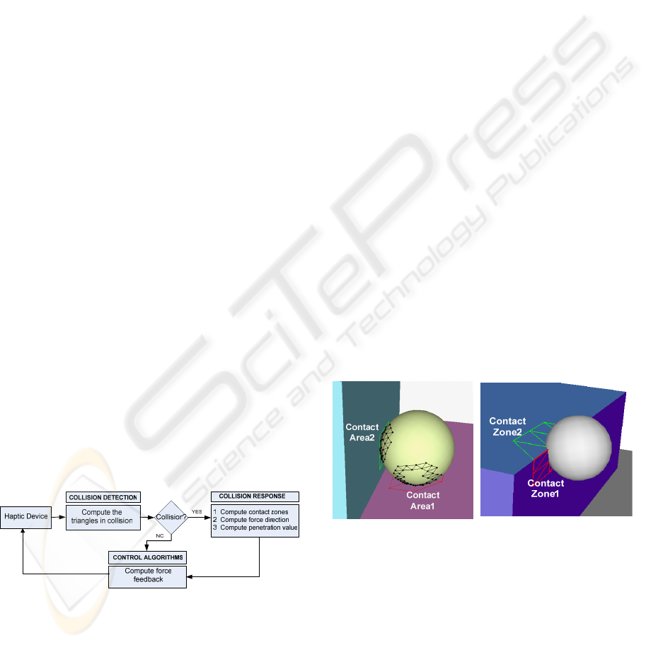
Figure 1 shows the scheme of the haptic
rendering algorithm.
Figure 1: Scheme of the haptic rendering algorithm.
When two objects collide, the group of collided
triangles of the static object constitute the “static
collision set”. The method proposed in this article
subdivides this set into areas called “contact areas”
in order to compute contact forces. Each triangle in a
contact area shares at least one edge with other
triangle in its area (see Figure 2a). This division is
helpful in order to obtain information about the
nature of the geometry in collision, making easier
the computation of the final reaction force. Next
subsections explain the phases that the proposed
collision response algorithm follows for each contact
area.
It is well-known that the simulation of non-
penetrating rigid body dynamics increases the
perceived stiffness of the environment (Srinivasan et
al., 1996). In fact, our system does not allow the
mobile object to interpenetrate visually into the
mock-ups in order to simulate realistic contacts on
the objects’ surfaces. However, we have decided to
disable this option in all figures with the purpose of
providing a clearer graphical view of the situations.
4.1 Calculate Contact Zones
In the first phase, the collision response module
subdivides the collision area into different contact
zones taking into account sharp edges (surface
discontinuities). Triangles in a contact zone are
connected among them and all the shared edges are
smooth. When two triangles share an edge and the
angle between the normals to both triangles is lower
than a fixed value (crease angle), the edge has a
“smooth label”.
There will be as many contact zones as necessary
to satisfy the smooth connectivity condition (see
Figure 2b). Each contact zone approximates a C
1
surface patch.
(a) (b)
Figure 2: Type of contacts. The triangles in red and green
represents the colliding triangles of the static model and
the black ones belong to the mobile object. Two contact
areas, each with two one contact zone (a) and one contact
area with two contact zones (b).
For instance, when a collision is detected in a flat
surface, all the triangles of the static object in
collision will have the same normal vector, and the
angle between them will be zero. In that case, there
will only be one contact zone. However, when the
GRAPP 2007 - International Conference on Computer Graphics Theory and Applications
148
collision is detected in a corner, there will be
different normal vectors in collision. Creating
contact zones for these cases, gives information
about the nature of the geometry in collision, and it
helps to compute a proper force feedback.
Each contact zone is represented by a zone
contact normal that is computed as the vectorial sum
of all triangles’ normals which belong to that contact
zone.
4.2 Area Contact Normal
Adequate contact normals permit providing suitable
haptic forces. Three cases can be distinguished
depending on the number of computed contact
zones.
If no triangles in the contact area share a sharp
edge, there is a unique contact zone. In case of rigid
and frictionless objects, the reaction force direction
is normal to the object surface. Therefore, the
solution is trivial since the area contact normal is the
zone contact normal.
When a contact area has two or more contact
zones, the contact has happened in an area of the
static object that is not a continuous surface (a C
0
area). In this case, the area contact normal must be
computed in the mobile object. It is because the fact
that the normals of static object do not provide
enough information to obtain a suitable direction
without sudden changes. This is performed using the
triangles in the mobile object that collide with the
static object. Note that this normal orientation must
be reversed.
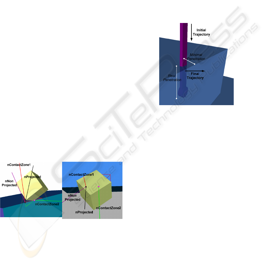
(a) (b)
Figure 3: Contact state without C
1
in the static model and
mobile object (a) and solution for this problem projecting
the normal obtained (b).
However, collision situations, where there is not
a C
1
contact area in the static object nor in the
mobile one, often happen in real applications. These
situations often lead to abrupt changes in contact
normal in consecutive simulation steps (Figure 3).
For the purpose of avoiding these situations, the
contact normal is projected on a plane defined by the
cross product of the zone contact normals.
4.3 Penetration Depth Computation
Many good algorithms to estimate the penetration
value are known (Cameron, 1997, Kim et al., 2003,
Redon and Lin, 2006). The penetration depth value
is considered as the minimum translational distance
required to separate two objects. However, this
optimal translation could provide a non useful result,
as Figure 4 shows.
Figure 4: The minimal penetration push away the virtual
tool to the right instead of up direction.
Another problem is that in some collision states,
triangles from one object are completely inside the
other object. When this happens, those triangles do
not appear in the list of colliding triangles and
further computing should be required.
It is supposed that the stiffness of virtual
environment would be high enough to avoid large
interpenetration of objects. However, high stiff
values cause instabilities in the system; therefore a
small penetration will be allowed enabling the
existence of triangles completely inside the static
object.
The proposed method computes a fast
approximation of the penetration depth value. It is
determined by the distance from the most remote
internal vertex to the area contact plane, which is
defined by the normal computed in the previous
step. The aim is to measure the penetration in the
same direction in which the virtual tool will be
rejected to the surface.
In order to reduce the computational cost of
determining a penetration value, instead of the
global geometric problem, a local method based on a
bounding volume has been used. Spheres that cover
STABLE HAPTIC RESPONSE FOR COMPLEX INTERACTIONS
149
contact zones have been tested. For each contact
zone, the centroid is computed in order to place the
centre of the sphere and its radius will depend on the
area of each contact zone, being large enough to
contain all these vertices.
Mobile object vertices (internal vertices) that are
inside this sphere will be processed to compute the
penetration value. The zone contact normal defines
two hemi-spheres, one “internal” and the other one
“external”, referred to the static object. The vertices
of the mobile object that are in the internal semi-
sphere will be used to compute penetration.
The use of these spheres is not necessarily exact,
but simplifies the problem of finding “internal”
mobile vertices. We consider that this approximation
is specially useful when the mobile objects used to
interact with the mock-up are complex, thin and long
(Figure 5), such as the tools utilized in
maintainability tasks (screwdriver, adjustable
spanner…).
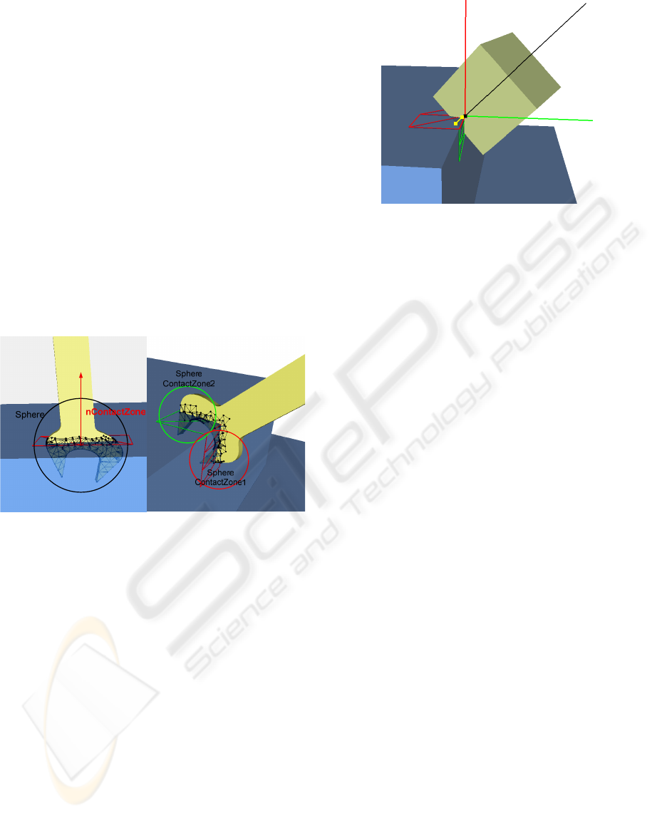
(a) (b)
Figure 5: Examples where the use of sphere could be
useful since it reduces the vertices to analyze. One contact
zone (a) and two contact zones (b).
A point is needed to define completely the area
contact plane. When there is only one contact zone,
the area contact plane is defined with the centre of
the sphere.
If there are more than one contact zone, the set of
internal vertices is the union of the internal vertices
for each zone. The common vertices among these
zones could be used to place the contact plane
(Figure 6).
nContactZone1
nFinal
nContactZone2
ContactZone1
ContactZone2
Penetration
Figure 6: Example of final haptic response: nFinal and
penetration value in yellow. The black point represents the
common point between the two contact zones.
5 EXPERIMENTS AND RESULTS
We have implemented our algorithm on a PC
running Windows XP operating system with a
Pentium Dual Core 6600, 2GB memory and an
NVIDIA GeForce 7900 GS. We have developed the
algorithm described in this paper and integrated it in
a simulation of contact interaction using 3D models
with sharp edges.
We rendered the motion of a virtual tool through
a convex corner, paying particular attention to the
speed rate and quality of force feedback, which are
the two of the most important features that a
collision response method must fulfil. As explained
before, haptic instabilities arise from the delay in the
collision detection computation and because of
abrupt changes in the haptic force value and
direction.
In order to analyze the efficiency of these two
aspects, two different types of experiments have
been accomplished. The first experiment analyzes
the influence of mobile object’s tessellation on the
penetration computation. On the other hand, the
second experiment studies the direction of computed
haptic response. We have also analyzed the users’
perception for the proposed method.
5.1 Penetration Study
The aim of this experiment is to study the influence
of tessellation on the penetration computation. This
is an important point for all methods that are based
on geometrical approximations. However, it is even
more important when a stable and comfortable
haptic response is sought. In these cases, it is
advisable to prevent large penetration values in order
GRAPP 2007 - International Conference on Computer Graphics Theory and Applications
150
to avoid abrupt changes in the force magnitude,
which might inconvenience users.
We have recorded an ideal haptic device
trajectory in which a cubic mobile object is covering
a convex edge of the virtual scenario consisted of
45.000 triangles. Then, this trajectory is played
using the same mobile object but with different
tessellation levels.
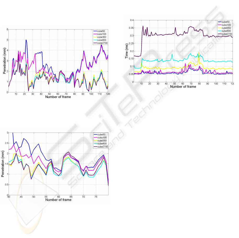
Figure 7 shows the penetration measured for
different tessellations of the virtual tool. The cube
has been non-uniformly tessellated using 50, 100,
350, 800 and 2700 triangles, which correspond to
30, 20, 10, 8, and 4 mm triangle edge length average
approximately.
Figure 7: Measured penetration depths using different
tessellations for the mobile object.
Figure 8: Detail of the previous figure from 40 to 80 frame
number.
The results show that coarse tessellations
generate important discontinuities since penetration
values and the magnitude variation between
different frames is larger than using a more detailed
tessellation. In addition to this, it can be shown that
a too detailed tessellation is not required, as we
obtain similar penetration values with the three last
levels of tessellation. Figure 8 provides a detail of
the graph where this fact can be better visualized.
We have also measured the time performance in
terms of the time required to accomplish the
different phases of the proposed method (Figure 9).
This experiment has been performed without using
the spheres which can reduce the number of vertices
to analyze in the third phase of the algorithm. The
purpose of this experiment is to show that our
method achieves good time results, which even
could be improved using the bounding volumes.
Figure 9: Time spent by the proposed method computing
the collision response.
5.2 Force Direction Study
The purpose of this experiment is to measure the
quality of the computed force. We can deduce
whether the computed force response is valid or not
analyzing the direction and module of this force.
We consider that sudden changes in the force
direction and module can result in force
discontinuities or un-stable behaviour, which can
produce a defective perception of the collision force.
Previous works (Morgenbesser and Srinivasan,
1996) have also studied the influence of abrupt
changes in the force direction and how sensitive are
humans to these changes.
In this second experiment, it has been simulated
the motion of a virtual tool through a convex corner.
To be precise, we have used a sphere of radius 50
mm and a fixed penetration of 10 mm. In Figure 10,
blue line represents the surface of the convex corner
in 2D. On the other hand, red lines are the vectorial
representations of the force computed by the
collision response methods for each point of the
trajectory.
We have compared the results of our proposed
collision response method with another method that
STABLE HAPTIC RESPONSE FOR COMPLEX INTERACTIONS
151

simply computes a haptic force with an angle of 45º
at any corner situation. As it can be noticed in the
Figure 10a, the force direction suffers abrupt
changes when entering or leaving the corner,
producing a defective perception.
(a) (b)
Figure 10: Force directions in a simulated convex edge
using a force response with an angle of 45º (a) and our
proposal method (b).
Otherwise, the proposed method provides a
progressive change in the force direction (Figure
10b), which avoids instabilities in the final force. In
this case, the user can go around feeling a rounded
corner, as it happens when we cover a real corner
using the finger.
5.3 User Perception
It is quite clear that the method that simply computes
forces in corners with an angle of 45º is not feasible
because of the instabilities and abrupt forces that it
produces.
The method proposed in this paper induces a
“rounded corner” feeling to the user, i.e., the user
can go around corners and the perceived haptic force
changes its direction in a progressive way avoiding
sudden changes in the force direction. This method
guarantees stability, but the trajectory of the
direction of the haptic force is more similar to that
when touching a cylindrical object, rather than a
sharp corner. In some way, this method imitates a
path through a real corner, but touching the corner
with one of our fingers instead of a tool. In real
world, it is easier to go around a corner with a finger
than with a tool like a pen. This is due to the fact
that the finger suffers deformation and the contact is
physically more stable.
We have made several experiments with
different users and they consider that the proposed
method is very comfortable to interact with.
Although this method does not represent accurately
the real physical reactions, users prefer this
behaviour.
We also consider that users’ perception does not
only have a technical factor but also a very
important psychological one that could be improved
using a multisensory approach to simulate haptic
applications. This multisensory concept in haptic
interfaces is being studied deeply nowadays. For
instance, factors like stereo vision, visually non-
penetrating collisions and sound can make the
system more immersive (Díaz et al., 2006) and
enhance the user perception. In a similar way, some
applications should focus more on comfortable
haptic interface than in replicating “exact” physical
behaviours.
6 CONCLUSIONS
A collision response method that deals with complex
collision interactions such sharp edges has been
presented. It avoids abrupt changes in the haptic
force direction and magnitude, improving in this
way overall stability of the haptic system.
The experiments accomplished show that this
algorithm generates continuous haptic response in
complex collisions. Users also prefer this smooth
working environment.
As future work, we are working on enhancing
the performance of the system to use it in complex
environments and extend it to support future 6-DOF
haptic interactions with torques. Moreover, we
intend to continue researching solutions to
problematic geometrical situations such as peg-in-
hole tasks and interaction with thin objects.
REFERENCES
Basdogan, C., De, S., Kim, J., Muniyandi, M., Kim, H. &
Srinivasan, M. A. (2004) Haptics in Minimally
Invasive Surgical Simulation and Training. IEEE
Computer Graphics and Applications, 24, 56-64.
Basdogan, C. & Srinivasan, M. A. (2002) Haptic
Rendering in Virtual Environments. IN STANNEY,
K. M. (Ed.) Handbook of Virtual Environments:
Design, Implementation, and Applications (Human
Factors and Ergonomics). London, Lawrence
Earlbaum Inc.
Borro, D., García-Alonso, A. & Matey, L. (2004)
Approximation of Optimal Voxel Size for Collision
Detection in Maintainability Simulations within
Massive Virtual Environments. Computer Graphics
Forum.
GRAPP 2007 - International Conference on Computer Graphics Theory and Applications
152

Cameron, S. A. (1997) Enhancing GJK: Computing
Minimum and Penetration Distances between Convex
Polyhedra. IEEE International Conference on Robotics
and Automation (ICRA).
Díaz, I., Hernantes, J., Mansa, I., Lozano, A., Borro, D.,
Gil, J. J. & Sánchez, E. (2006) Influence of
Multisensory Feedback on Haptic Accesibility Tasks.
Virtual Reality, Special Issue on Multisensory
Interaction in Virtual Environments, 10, 31-40.
Garcia-Alonso, A., Gil, J. J. & Borro, D. (2005) Interfaces
for VR Applications Development in Design. Virtual
Concept'05. Biarritz, France.
Hasegawa, S. & Sato, M. (2004) Real-time Rigid Body
Simulation for Haptic Interactions Based on Contact
Volume of Polygonal Objects. Computer Graphics
Forum, 23, 529-538.
Ho, C.-H., Basdogan, C. & Srinivasan, M. A. (2000) Ray-
based haptic rendering: force and torque interactions
between a line probe and 3D objects in virtual
environments. 19, 668-683.
Kim, Y. J., Otaduy, M. A., Lin, M. C. & Manocha, D.
(2003) Six-Degree-of-Freedom Haptic Rendering
Using Incremental and Localized Computations.
Presence - Teleoperators and Virtual Environments,
Vol 12, 277-295.
Massie, T. H. & Salisbury, J. K. (1994) The PHANTOM
Haptic Interface: A Device for Probing Virtual
Objects. Winter Annual Meeting, Symposium on
Haptic Interfaces for Virtual Environment and
Teleoperator Systems. Chicago, IL, ASME.
Mcneely, W. A., Puterbaugh, K. D. & Troy, J. J. (1999)
Six Degree-of-Freedom Haptic Rendering Using
Voxel Sampling. ACM SIGGRAPH - Computer
Graphics. Los Angeles, California, USA.
Mcneely, W. A., Puterbaugh, K. D. & Troy, J. J. (2006)
Voxel-Based 6-DOF Haptic Rendering Improvements.
Haptics-e, 3.
Morgenbesser, H. B. & Srinivasan, M. A. (1996) Force
Shading for Haptic Shape Perception. The
International Symposium on Haptic Interfaces for
Virtual Environments and Teleoperator Systems.
Ortega, M., Redon, S. & Coquillart, S. (2006) A Six
Degree-of- Freedom God-Object Method for Haptic
Display of Rigid Bodies. IEEE International
Conference on Virtual Reality. Alexandria, Virginia,
USA.
Otaduy, M. A. & Lin, M. C. (2003) Sensation Preserving
Simplification for Haptic Rendering. SIGGRAPH. San
Diego, CA.
Otaduy, M. A. & Lin, M. C. (2005) Stable and Responsive
Six-Degree-of-Freedom Haptic Manipulation Using
Implicit Integration. World Haptics Conference. Pisa,
Italy.
Redon, S. & Lin, M. C. (2006) A Fast Method for Local
Penetration Depth Computation. Journal of Graphics
Tools (JGT), 11, 37-50.
Renz, M., Preusche, C., Pötke, M., Kriegel, H.-P. &
Hirzinger, G. (2001) Stable Haptic Interaction with
Virtual Environments Using an Adapted Voxmap-
PointShell Algorithm. Eurohaptics. Birmingham, UK.
Ruspini, D. C., Kolarov, K. & Khatib, O. (1997) The
Haptic Display of Complex Graphical Environments.
SIGGRAPH 97.
Salisbury, K., Brock, D., Massie, T., Swarup, N. & Zilles,
C. (1995) Haptic Rendering: Programming Touch
Interaction with Virtual Objects. ACM Symposium on
Interactive 3D Graphics. Monterey, California, USA.
Savall, J., Borro, D., Amundarain, A., Martin, J., J. Gil, J.
& Matey, L. (2004) LHIfAM - Large Haptic Interface
for Aeronautics Maintainability. International
Conference on Robotics & Automation (audiovisual
material). New Orleans, LA, USA, IEEE.
Srinivasan, M. A., G.L, B. & Brock, D. L. (1996) The
Impact of Visual Information on the Haptic Perception
of Stiffness in Virtual Environments. ASME
International Mechanical Engineering Congress and
Exposition. Atlanta, USA.
Wan, M. & Mcneely, W. A. (2003) Quasi-Static
Approximation for 6 Degrees-of-Freedom Haptic
Rendering. IEE Visualization Conference (VIS'03).
Seattle, Washington, USA.
Zilles, C. B. & Salisbury, J. K. (1995) A Constraint-based
God-object Method For Haptic Display. IEE/RSJ
International Conference on Intelligents Robots and
Systems, Human Robot Interaction, and Cooperative
Robots.
STABLE HAPTIC RESPONSE FOR COMPLEX INTERACTIONS
153
