
MEASUREMENT OF CELL FORCES USING A POLYMER
MEMS SENSOR
Nicholas Ferrell, James Woodard and Derek Hansford
Department of Biomedical Engineering, Ohio State University, 1080 Carmack Rd. 270 Bevis Hall, Columubus, OH, USA
Keywords: Polymer MEMS, cell forces, microfabrication.
Abstract: Cellular mechanics are responsible for execution and regulation of a number of cell functions. Mechanical
forces generated within the cytoskeleton are transmitted via transmembrane linkages to the underlying
substrate. Measurement of these forces could lead to a wealth of additional information about the role of cell
mechanics in regulating cell function and signal transduction. Here we describe the design, fabrication, and
testing of a polystyrene cantilever beam array for measuring forces generated by WS1 human skin
fibroblasts. Finite element analysis was used to guide the design of a compound cantilever beam. Sensors
were fabricated from polystyrene to provide a well-studied and biocompatible surface for cell attachment.
Soft lithography based techniques were used for microfabrication of the sensors. Cells were placed on four
and eight probe cantilever sensors and deflection of the probes was measured optically during attachment
and spreading of the cells. The device was successfully used to measure time varying mechanical forces
generated by fibroblast cells.
1 INTRODUCTION
Mechanical forces generated by adherent cells play
an important role in execution and/or regulation of a
host of cellular processes. When anchorage
dependent cells attach to a surface, forces generated
in the cytoskeleton are transmitted to the underlying
substrate via transmembrane protein linkages. These
mechanical forces are involved in controlling cell
functions including adhesion, morphology, and
motility (Galbraith and Sheetz, 1998; Chicurel et al.,
1998) as well as apoptosis (Chen et al., 1997) and
wound healing (Wrobel et al., 2002) among others.
Measurement of mechanical forces generated by
adherent cells could provide additional insight into
the basic role of cell mechanics in regulating cell
function. In addition, monitoring time dependent cell
mechanics could lead to new routes of cell-based
sensing focused on mechanical changes in the cell
brought about by externally applied chemical or
mechanical stimuli.
Several devices have been utilized for observing
and measuring cellular forces. Some of the first
approaches involved growing cells on deformable
elastic substrates, which wrinkled in response to
mechanical forces (Harris et al., 1980; Beningno and
Wang, 2002). More recently, microfabrication
techniques have been used to fabricate force
measurement devices. This is an attractive approach
due to the ability to make precise structures on the
same size scale as biological cells. Galbraith and
Sheetz (1997) used micromachined silicon
cantilevers to measure localized forces generated by
fibroblasts. Single cantilevers with one direction of
motion were used, thus limiting the ability to
measuring forces directed along the axis of the
cantilever or determine the direction of the force.
Soft lithography based microfabrication techniques
(Xia and Whitesides, 1998) have also been used to
fabricate devices for measuring cell forces (Tan, et
al., 2003). In this case, elastic
poly(dimethylsiloxane) (PDMS) pillars acted as
vertical cantilevers. Cells were grown on top of the
pillars and deflections were measured and used to
calculate the force on each pillar.
Our approach to measurement of cell forces
involves the use of a polystyrene cantilever array
with a compound beam design. The compound beam
allows the forces to be measured in all directions,
thus allowing calculation of both the force
magnitude and direction. The choice of polystyrene
as the structural material also has a significant
impact on the function of the device. Polystyrene is
151
Ferrell N., Woodard J. and Hansford D. (2008).
MEASUREMENT OF CELL FORCES USING A POLYMER MEMS SENSOR.
In Proceedings of the First International Conference on Biomedical Electronics and Devices, pages 151-155
DOI: 10.5220/0001055001510155
Copyright
c
SciTePress

a well-characterized biocompatible material that is
used ubiquitously in cell culture applications. In
addition, it is well know that the stiffness of the
substrate can significantly affect the mechanical
behaviour of cells (Lo et al., 2000, Choquet et al.,
1997). Most devices to date have been fabricated
from relatively flexible (silicone rubber) or
relatively stiff (silicon) materials. In this case we use
a materials with intermediate stiffness.
The device consists of a four or eight probe
cantilever array fixed to a glass substrate at the base
of the beams. The ends of the beams were designed
to provide adequate surface area for cell spreading.
The fixed post at the center of the device was
included to provide a location for initial cell
attachment as well as provide a fixed reference point
for probe deflection analysis. As the cell attaches to
the beams and exerts forces, the deflection of each
cantilever is measured optically over time to give
spatially and temporally resolved measurement
capabilities.
2 MATERIALS AND METHODS
2.1
Device Fabrication and
Characterization
Devices were fabricated using sacrificial layer
micromolding as described in (Ferrell et al., 2007).
A water-soluble sacrificial layer was first patterned
by photolithography and reactive ion etching. A
layer of poly(vinyl alcohol) (PVA) was dissolved in
water to a final concentration of 10% (wt/wt). The
PVA solution was spin coated on 18 mm glass
coverslips at 1000 rpm. A protective layer of
poly(methyl methacrylate) (PMMA) was then spin
coated on top of the PVA. The PMMA layer
protected the PVA from the developer in the
upcoming photolithography process.
Photolithography was then used to pattern an etch
mask on the PVA/PMMA films. Reactive ion
etching in an O
2
plasma was used to removed both
the PVA and PMMA in the unmasked regions. The
remaining photoresist and PMMA layers were then
removed by sonication in acetone, leaving only the
patterned PVA.
A PDMS mold of the device was fabricated by
replica molding (Xia and Whitesides, 1998) of a
photolithographically patterned master. The PDMS
mold was spin coated with a solution of polystyrene
in anisole (7.5% wt/wt). The polystyrene was
removed from the raised portions of the mold by
contact with a glass slide heated to 200 ºC. The
remaining polystyrene was left in the recessed
portion of the mold. The mold was aligned with the
sacrificial layer and heat (120 ºC) and pressure (75
psi) were used to transfer the device onto the
sacrificial layer. The device was then annealed at
115 ºC for 15 minutes to improve adhesion of the
anchor regions and remove any residual stress in the
beams.
The thickness of each device was characterized
using a stylus profilometer. The thickness range for
the above processing parameters was 1.31-1.75 µm.
2.2 Design and Simulations
Finite element simulations (ANSYS) were used to
guide the design of the cantilever beam. The beam
was designed to give reasonable x,y deflection
response while still conforming to the geometrical
constraints of the devices circular configuration. The
deflection plot for a 5 nN force applied to an area at
the end of the cantilever beam at 10º increments
from 0º to 360º is shown in Figure 1.
An ideal beam response would be a circular
deflection profile with no offset between the
direction of the beam deflection and the force
direction. The plot shows a slight offset. The plot
also shows that the beam is stiffer in the 90º and
270º directions compared to the 0º and 180º
directions. This leads to slightly less sensitivity to
forces in those general directions, but the overall
response of the beam is adequate for the application
described here.
2.3 Cell Culture and Image Acquisition
The cells used in this study were WS1 human skin
fibroblasts (ATCC). Cells were cultured in
Minimum Essential Medium, Eagle (ATCC)
supplemented with 10% fetal bovine serum and 1%
penicillin-streptomycin. Cells were cultured at 37ºC
in a 5% CO
2
atmosphere. To obtain cells for
measurements, cells were detached from T75 tissue
culture flasks using .25% trypsin-EDTA.
Prior to performing measurements, the devices
were modified by a brief exposure to O
2
plasma in a
reactive ion etcher to make the surface more
hydrophilic and improve cell attachment. Devices
were fixed to a PDMS coated petri dish. The PDMS
coated dish allowed fixation of the device without
the use of a chemical adhesive. The devices were
placed in cell culture medium to dissolve the
sacrificial layer. After complete dissolution of the
BIODEVICES 2008 - International Conference on Biomedical Electronics and Devices
152
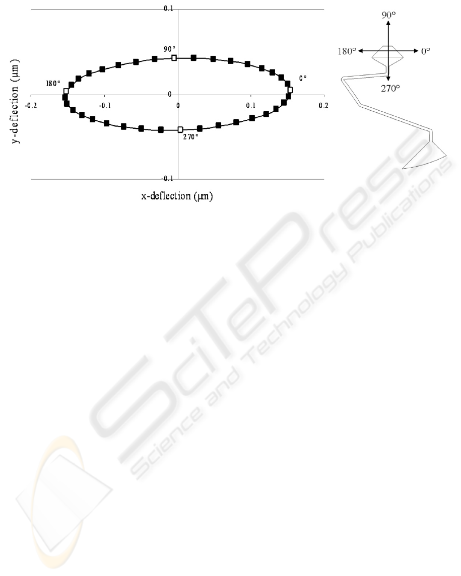
Figure 1: Deflection plot for the compound cantilever beam with a 5 nN applied load.
PVA layer, the medium was aspirated and fresh
medium was added and aspirated three times to
remove the majority of the dissolved PVA. 20 ml of
fresh medium without cells was added to the petri
dish. A few drops of cell suspension were then
added to the dish. This provided a low cell density
and minimized the likelihood of having multiple
cells on a single device.
Measurements were performed on an inverted
microscope (Nikon TS100) with a custom stage
incubator. The incubator consisted of an acrylic
enclosure with the temperature regulated at 37ºC and
supplied with 5% CO
2
. A manual micromanipulator
(World Precision Instruments) with a 2µm inner
diameter glass micropipette was used to position a
single cell on the center region of sensor. Cells were
moved onto the device with the microscopy in phase
contrast mode to allow better visualization. A 6.6
megapixel CCD camera (Pixelink) was set to capture
images at 30 second intervals for the duration of the
experiment. For analysis, the phase contrast filter
was removed and brightfield images were captured
to facilitate easier edge detection.
2.4 Image Analysis and Force
Calculation
Images were analysed using NIH Image J software
(download available at http://rsb.info.nih.gov/ij/).
The x,y position of the end of the probe as well as a
fixed point on the device were determined prior to
cell attachment. The x,y displacement of the end of
each the cantilever was then monitored over time.
The x,y position of the fixed point was also
monitored to determine and correct for image shift.
After determining the magnitude and direction of the
cantilever deformation, the force magnitude and
direction were calculated based on the finite element
simulations.
3 RESULTS AND DISCUSSION
Scanning electron micrographs of the four probe
sensor prior to removal of the sacrificial layer are
shown in Figure 2. Figure 2(a) shows the entire
device with the anchor region at the outer perimeter
of the device. The close-up of the center of the
device shows the four adhesion pads as well as the
fixed post.
The force versus time plots for two different
experiments are shown in Figure 3 (a,c). The plots
show the force magnitude for each of the four
probes. Figure 3(a) shows that force is exerted on
each of the four probes. The graph also indicates that
the cell adhered to the sensor relatively quickly after
being placed on the device. Figure 3(c) shows that
force is only exerted on three of the four probes and
the magnitude of the force is significantly higher for
probes 1 and 3 compared to probe 4. This is likely
due at least in part to a smaller adhesion area on
probe 4 as compared to probes 1 and 3. This could
be a result of off center cell attachment and
spreading. In addition, Figure 3(c) shows that there
is a period of time prior to cell attachment with no
force generation. The plot clearly shows the onset of
MEASUREMENT OF CELL FORCES USING A POLYMER MEMS SENSOR
153
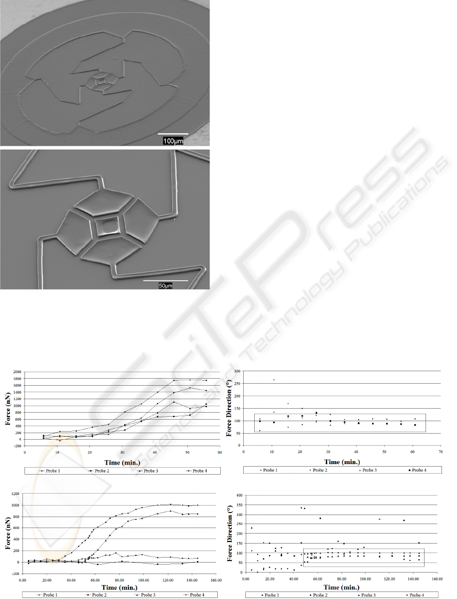
Figure 2: SEM micrographs of the cell force sensor.
cell attachment and force generation for each of the
probes. Probe 2 showed no force/deflection response
attributed to cell mechanics. The data is included to
show the noise in the measurement and analysis
system.
The angle of the force vectors are shown in
Figure 3(b,d). The boxes highlight that most of the
forces are oriented around 90º or toward the center
of the devices. This is expected given the nature of
the forces. In figure 3(d) the random orientation of
the angle prior cell attachment and for probe 2 are
due to noise.
Figure 4 shows optical phase contract
micrographs of the cantilevers corresponding to the
force and direction plots in Figure 3 (a,c). The force
vectors for each probe are overlaid on the images.
The images show the changes in the both the
magnitude and direction of the deformation at 0, 30,
37.5, and 50 minutes.
4 CONCLUSIONS
A novel force sensor was designed and fabricated
for measurement of mechanical forces generated by
fibroblast cells. The sensor was designed with the
aid of finite element simulations of the sensor
behavior. The device was fabricated from
polystyrene using a soft lithography based
fabrication procedure. Force magnitudes and
directions were measured using WS1 skin fibroblast
and show the ability to measure variation in the cell
mechanics over time.
Figure 3: (a,c) Force magnitude versus time for two separate experiments. (b,d) Force direction corresponding to the forces
in (a,c). The boxes highlight that the majority of the forces are oriented in the direction toward the center of the structure.
(a)
(b)
(
c
)
(d)
(
a
)
(
b
)
BIODEVICES 2008 - International Conference on Biomedical Electronics and Devices
154

Figure 4: Phase contract micrographs with vector force overlays at (a) 0 min. (b) 30 min. (c) 37.5 min. and (d) 50 min. Note
the difference in the force vector scale in (d).
ACKNOWLEDGEMENTS
The authors would like to thank Derek Ditmer and
Paul Stefan at the Ohio Nanotech West Laboratory
for technical assistance. We also thank Derek
Ditmer and Landon McCaroll for assistance with
image analysis.
REFERENCES
Beningo, K.A., Wang, Y., 2002. Flexible substrata for the
detection of cellular traction forces. Trends in Cell
Biology, 12, 79-84.
Chen, C.S., Mrksich, M., Huang, S., Whitesides, G.M.,
Ingber, D.E., 1997. Geometric control of cell life and
death. Science, 276, 1425-1428.
Chicurel, M.E., Chen, C.S., Ingber, D.E., 1998. Cellular
control lied in the balance of forces. Current Opinions
in Cell Biology, 10, 232-239.
Choquet, D., Felsenfeld, D.P., Sheetz, M.P., 1997.
Extracellular matrix rigidity causes strengthening of
integrin-cytoskeletal linkages. Cell, 88, 39-48.
Ferrell, N., Woodard, J., Hansford, D., 2007. Fabrication
of polymer microstructures for MEMS: sacrificial
layer micromolding and patterned substrate
micromolding. Biomedical Microdevices, 9, 815-821.
Glabraith, C.G., Sheetz, M.P., 1998. Forces on adhesive
contacts affect cell function. Current Opinions in Cell
Biology, 10, 566-571.
Galbraith, C.G., Sheetz, M.P., 1997. A micromachined
devices provides a new bend on fibroblast traction
forces. PNAS, 94, 9114-9118.
Harris, A.K., Wild, P., Stopak, D., 1980. Silicone rubber
substrata: a new wrinkle in the study of cell
locomotion. Science, 208, 177-179.
Lo, C., Wang, H., Dembo, M., Wang, Y., 2000. Cell
movement is guided by the rigidity of the substrate.
Biophysical Journal, 79, 144-152.
Tan, J.L., Tien, J., Pirone, D.M., Gray, D.S., Bhadriraju,
K., Chen, C.S., 2003. Cell lying on a bed of
microneedles: an approach to isolate mechanical force.
PNAS, 100, 1484-1489.
Wrobel, L.K., Fray, T.R., Molloy, J.E., Adams, J.J.,
Armitage, M.P., Sparrow, J.C., 2002. Contractility of
Single Human Dermal Myofibroblasts and Fibroblasts.
Cell Motility and Cytoskeleton., 52, 82-90.
Xia, Y., Whitesides, G.M., 1998. Soft lithography. Angew.
Chem. Int. Ed., 37, 550-575.
(c)
(
d
)
(
a
)
(
b
)
MEASUREMENT OF CELL FORCES USING A POLYMER MEMS SENSOR
155
