
TRILATERATION LOCALIZATION FOR MULTI-ROBOT TEAMS
P
aul M. Maxim
1
, Suranga Hettiarachchi
2
, William M. Spears
1
, Diana F. Spears
1
Jerry Hamann
1
, Thomas Kunkel
1
and Caleb Speiser
1
1
University of Wyoming, Laramie, Wyoming 82070, U.S.A.
2
Eastern Oregon University, La Grande, Oregon 97850, U.S.A.
Keywords:
Localization, trilateration, formations, distributed, outdoor.
Abstract:
The ability of robots to quickly and accurately localize their neighbors is extremely important for robotic
teams. Prior approaches typically rely either on global information provided by GPS, beacons and landmarks,
or on complex local information provided by vision systems. In this paper we describe our trilateration ap-
proach to multi-robot localization, which is fully distributed, inexpensive, and scalable (Heil, 2004). Our prior
research (Spears et. al, 2006) focused on maintaining multi-robot formations indoors using trilateration. This
paper pushes the limits of our trilateration technology by testing formations of robots in an outdoor setting at
larger inter-robot distances and higher speeds.
1 INTRODUCTION
The main contributions of this paper are: (1) a presen-
tation of our trilateration approach to multi-robot lo-
calization (i.e., each robot locates its neighbors), and
(2) a set of experimental results obtained with our tri-
lateration approach under outdoor conditions. These
experimental results highlight the advantages of our
approach and clarify its limitations. The outdoor ex-
periments are conducted in an environment with vary-
ing terrain (e.g., grass, dirt, and concrete), rocks, pro-
truding tree roots, leaves, pine cones and other ground
protrusions. Also, there was a considerable amount
of dust and wind (over 9 meters per second). Despite
this, the robots are able to maintain high quality for-
mations.
The organization of this paper is as follows. Sec-
tion 2 introduces our trilateration approach to local-
ization, which is fully distributed and assumes that
each robot has its own local coordinate frame (i.e.,
no global information is required). Each robot deter-
mines its neighbors’ range and bearing with respect
to its own egocentric, local coordinate system. After
such localization, sensor values and other data can be
exchanged between robots in a straightforward man-
ner. Next, sections 3, 4 and 5 describe our trilatera-
tion implementation and current robot platforms. Sec-
tions 6 and 7 present results from our experiments.
Section 8 summarizes and concludes the paper.
2 LOCALIZATION VIA
TRILATERATION
The purpose of our trilateration technology is to cre-
ate a plug-in hardware module to accurately local-
ize neighboring robots, without global information
and/or the use of vision systems. Our localiza-
tion technology does not preclude the use of other
technologies. Beacons, landmarks, vision systems,
GPS (Borenstein et. al, 1996), and pheromones
are not necessary, but they can be added if de-
sired. It is important to note that our trilateration
approach is not restricted to one particular class of
control algorithms – it is useful for behavior-based
approaches (Balch and Hybinette, 2000), control-
theoretic approaches (Fax and Murray, 2004; Fierro
et. al, 2002), motor schema algorithms (Brogan and
Hodgins, 1997), and physicomimetics (Spears et. al,
2004; Zarzhitsky et. al, 2005; Hettiarachchi, 2007).
In 2D trilateration, the locations of three base
points are known as well as the distances from each
of these three base points to the object to be localized.
Looked at visually, 2D trilateration involves finding
the location where three circles intersect. Thus, to lo-
cate a robot using 2D trilateration the sensing robot
must know the locations of three points in its own
coordinate system and be able to measure distances
from these three points to the sensed robot.
301
M. Maxim P., Hettiarachchi S., M. Spears W., F. Spears D., Hamann J., Kunkel T. and Speiser C. (2008).
TRILATERATION LOCALIZATION FOR MULTI-ROBOT TEAMS.
In Proceedings of the Fifth International Conference on Informatics in Control, Automation and Robotics, pages 301-307
DOI: 10.5220/0001508803010307
Copyright
c
SciTePress

2.1 Measuring Distance
Our distance measurement method exploits the fact
that sound travelssignificantly more slowly than light,
thereby enabling us to employ a Difference in Time of
Arrival technique. To tie this to 2D trilateration, as-
sume that each robot has one radio frequency (RF)
transceiver and three ultrasonic acoustic transducers.
The ultrasonic transducers are the “base points.” Sup-
pose robot 2 simultaneously emits an RF pulse and an
ultrasonic acoustic pulse. When robot 1 receives the
RF pulse (almost instantaneously), a clock on robot 1
starts. When the acoustic pulse is received by each of
the three ultrasonic transducers on robot 1, the elapsed
times are computed. These three times are converted
to distances, according to the speed of sound. Be-
cause the locations of the acoustic transducers are
known, robot 1 is now able to use trilateration to com-
pute the location of robot 2 (precisely, the location of
the emitting acoustic transducer on robot 2). Of the
three acoustic transducers, all three must be capable
of receiving, but only one must be capable of trans-
mitting.
Measuring the elapsed times is not difficult. Since
the speed of sound is roughly 340.2 meters per second
at standard temperature and pressure, it takes approx-
imately 2.9 ms for sound to travel one meter. Times of
this magnitude are easily measured using inexpensive
electronic hardware.
2.2 Channeling Acoustic Energy into a
Plane
Ultrasonic acoustic transducers produce a cone of en-
ergy along a line perpendicular to the surface of the
transducer. The width of this main lobe (for the in-
expensive 40 kHz transducers used in our implemen-
tation) is roughly 30
◦
. To produce acoustic energy
in a 2D plane would require 12 acoustic transducers
in a ring. To get three base points would hence re-
quire 36 transducers. This is expensive and is a large
power drain. We adopted an alternative approach.
Each base point is comprised of one acoustic trans-
ducer pointing downward. A parabolic cone (Heil,
2004) is positioned under the transducer, with its tip
pointing up toward the transducer (see Figure 2 later
in this paper). The parabolic cone acts like a lens.
When the transducer is placed at the virtual “focal
point” the cone “collects” acoustic energy in the hor-
izontal plane, and focuses this energy to the receiving
acoustic transducer. Similarly, a cone also functions
in the reverse, reflecting transmitted acoustic energy
into the horizontal plane. This works extremely well
– the acoustic energy is detectable to a distance of 3.5
m. which is adequate for our needs. Greater range
can be obtained with more power (the scaling appears
to be quite manageable).
2.3 Related Work
Trilateration is a well-known technique for robot lo-
calization. Most approaches (including ours) are al-
gebraic, although recently a geometric method was
proposed (Thomas and Ros, 2005). Many localiza-
tion techniques, including those involving trilatera-
tion, use global coordinates (Peasgood et. al, 2005);
however ours relies on local coordinates only.
MacArthur (MacArthur, 2003) presents two dif-
ferent trilateration systems. The first uses three acous-
tic transducers, but without RF. Localization is based
on the differences between distances rather than the
distances themselves. The three acoustic transducers
are arranged in a line. The second uses two acoustic
transducers and RF in a method similar to our own.
Unfortunately, both systems can only localize points
“in front” of the line.
Cricket (Nissanka, 2005) is another system that
makes use of RF and ultrasound for localization. It
was developed to be used indoors. Compared to our
system, which does not require fixed beacons, the
Cricket requires beacons attached to fixed locations
in order to function. This is not practical for mobile
robot localization in outdoor environments.
Our particular approach was inspired by the CMU
Millibot project. They also use RF and acoustic trans-
ducers for trilateration. However, due to size lim-
itations, each Millibot has only one acoustic trans-
ducer (coupled with a right-angle cone, rather than
the parabolic cone we use). Hence trilateration is a
collaborative endeavor that involves several robots.
To perform trilateration, a minimum of three Milli-
bots must be stationary and serve as beacons at any
moment in time. The set of three stationary robots
changes as the robot team moves. The minimum team
size is four robots (and is preferably five). Initializa-
tion generally involves having some robots make L-
shaped maneuvers, in order to disambiguate the local-
ization (Navarro-Serment, 1999). Our approach oper-
ates with as few as two robots (but is scalable to an
arbitrary number), due to the presence of three acous-
tic transducers on each robot (see below).
In terms of functionality, an alternative localiza-
tion method in robotics is to use line-of-sight infra-
red (IR) transceivers. When IR is received, signal
strength provides an estimate of distance. The IR sig-
nal can also be modulated to provide communication.
Multiple IR sensors can be used to provide the bear-
ing to the transmitting robot (e.g., see (Rothermich
ICINCO 2008 - International Conference on Informatics in Control, Automation and Robotics
302

et. al, 2004; Payton et. al, 2004)). We view this
method as complementary to our own; however, our
method is more appropriate for tasks where greater
localization accuracy is required. This is especially
important in outdoor situations where water vapor or
dust could change the IR opacity of air. Similar issues
arise with the use of cameras and omni-directional
mirrors/lenses, which require far more computational
power and a light source.
3 OUR TRILATERATION
APPROACH
Our trilateration approach to localization is illustrated
in Figure 1. Assume two robots, shown as circles. An
RF transceiver is in the center of each robot. Each
robot has three acoustic transducers (also called base
points), labeled A, B, and C. Note that the robot’s
local XY coordinate system is aligned with the L-
shaped configuration of the three acoustic transduc-
ers, as shown in the figure. Note, Y points to the front
of the robot.
&%
'$
s
ss
Robot 1
C
A
B
a
b
c
!
!
!
!
!
!
,
,
,
,
,
6Y
-
X
&%
'$
s
s s
Robot 2
C
A B
6
X
Y
Figure 1: Three base points in an XY coordinate system
pattern.
In Figure 1, robot 2 simultaneously emits an RF
pulse and an acoustic pulse from its transducer B.
Robot 1 then measures the distances a, b, and c. With-
out loss of generality, assume that transceiver B of
robot 1 is located at (x
1B
, y
1B
) = (0, 0) (Heil, 2004).
1
In other words, let A be at (0, d), B be at (0, 0), and C
be at (d, 0), where d is the distance between A and B,
and between B and C (see Figure 1).
For robot 1 to determine the position of B on robot
2 within its own coordinate system, it needs to find the
simultaneous solution of three nonlinear equations,
the intersecting circles with centers located at A, B
and C on robot 1 and respective radii of a, b, and c:
1
Subscripts denote the robot number and the acous-
tic transducer. The transducer A on robot 1 is located at
(x
1A
, y
1A
).
(x
2B
− x
1A
)
2
+ (y
2B
− y
1A
)
2
= a
2
(1)
(x
2B
− x
1B
)
2
+ (y
2B
− y
1B
)
2
= b
2
(2)
(x
2B
− x
1C
)
2
+ (y
2B
− y
1C
)
2
= c
2
(3)
Given the transducer configuration shown above, we
get (Heil, 2004):
x
2B
=
b
2
− c
2
+ d
2
2d
y
2B
=
b
2
− a
2
+ d
2
2d
An interesting benefit of these equations is that they
can be simplified even further, if one wants to trilater-
ate purely in hardware (Spears et. al, 2006).
By allowing robots to share coordinate systems,
robots can communicate their information arbitrarily
far throughout a robotic network. For example, sup-
pose robot 2 can localize robot 3. Robot 1 can local-
ize only robot 2. If robot 2 can also localize robot 1
(a fair assumption), then by passing this information
to robot 1, robot 1 can now determine the position of
robot 3. Furthermore, robot orientations can also be
determined. Naturally, localization errors can com-
pound as the path through the network increases in
length, but multiple paths can be used to alleviate this
problem to some degree. Heil (Heil, 2004) provides
details on these issues.
In addition to localization, our trilateration system
can also be used for data exchange. Instead of emit-
ting an RF pulse that contains no information but only
performs synchronization, we can also append data to
the RF pulse. Simple coordinate transformations al-
low robot 1 to convert the data from robot 2 (which is
in the coordinate frame of robot 2) to its own coordi-
nate frame.
4 TRILATERATION
IMPLEMENTATION
Figure 2 illustrate how our trilateration framework is
currently implemented in hardware. Figure 2 (left)
shows three acoustic transducers pointing down, with
reflective parabolic cones. The acoustic transducers
transmit and receive 40 kHz acoustic signals.
Figure 2 (middle) shows our in-house acoustic
sensor boards (denoted as “XSRF” boards, for Ex-
perimental Sonic Range Finder). There is one XSRF
board for each acoustic transducer. The XSRF board
calculates the time difference between receiving the
RF signal and the acoustic pulse. Each XSRF con-
tains 7 integrated circuit chips. A MAX362 chip con-
trols whether the board is in transmit or receive mode.
TRILATERATION LOCALIZATION FOR MULTI-ROBOT TEAMS
303
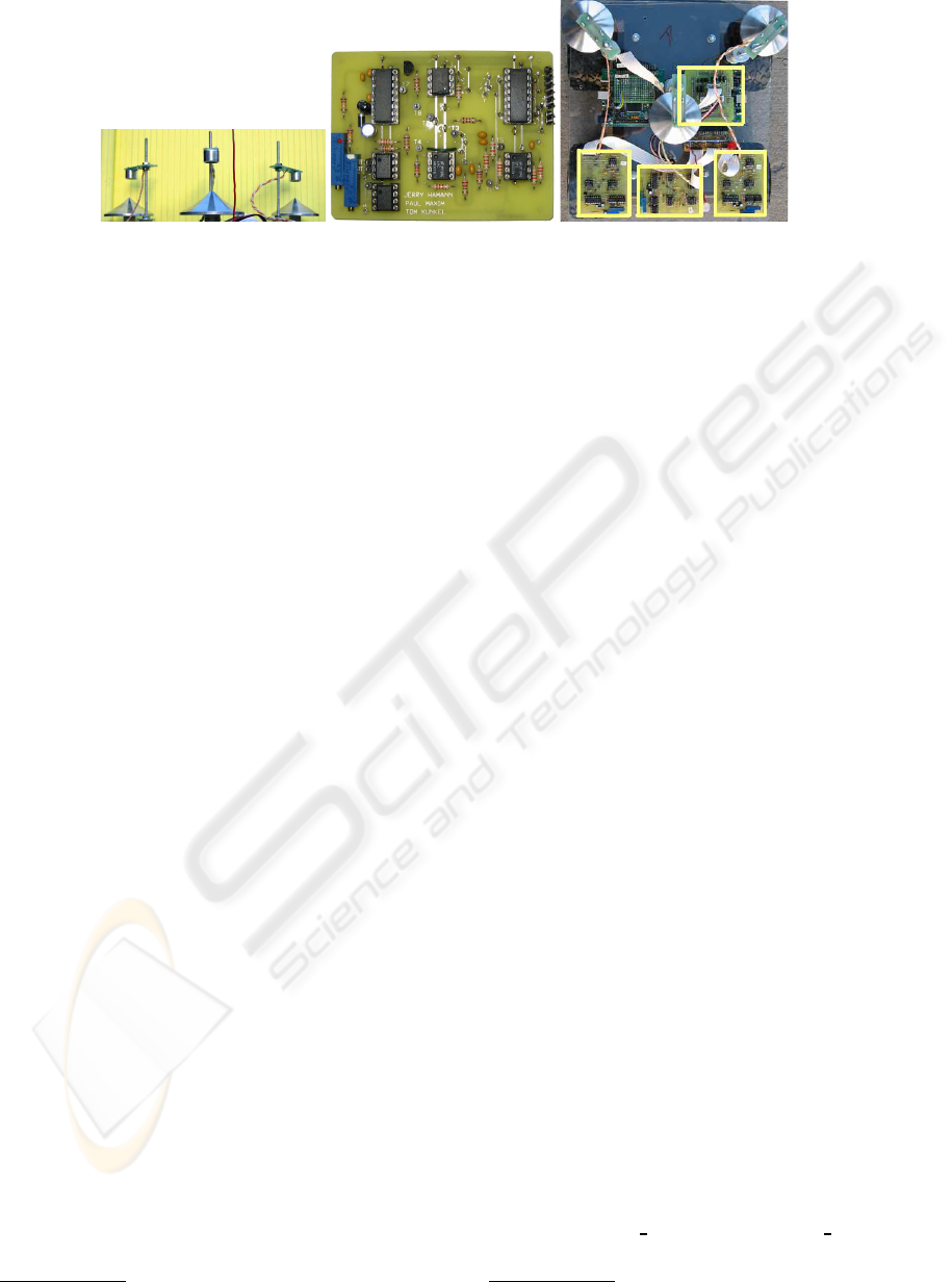
Figure 2: The acoustic transducers and parabolic cones (left). The XSRF acoustic sensor printed circuit board (middle), and
the completed trilateration module (top-down view, right).
When transmitting, a Microchip PIC microprocessor
generates a 40 kHz signal. This signal is sent to
an amplifier, which then interfaces with the acoustic
transducer. This generates the acoustic signal.
In receive mode, a trigger indicates that an RF sig-
nal has been heard and that an acoustic signal is arriv-
ing. When the RF is received, the XSRF board starts
counting. To enhance the sensitivity of the XSRF
board, three stages of amplification occur. Each of
the three stages is accomplished with a LMC6032 op-
erational amplifier, providing a gain of roughly 15
at each stage. Between the second and third stage
there is a 40 kHz bandpass filter to eliminate out-of-
bound noise that can lead to saturation. The signal is
then passed to two comparators, set at thresholds of
± 2 VDC. When the acoustic energy exceeds either
threshold, the XSRF board finishes counting, indicat-
ing the arrival of the acoustic signal.
The timing counts provided by each of the XSRF
boards is sent to a MiniDRAGON
2
powered by a
Freescale 68HCS12 microprocessor that performs the
trilateration calculations. Figure 2 (right) shows the
completed trilateration module from above. The
MiniDRAGON is outlined near the center and the
three XSRF boards are outlined at the bottom.
4.1 Synchronization Protocol
Trilateration involves at least two robots. One trans-
mits the acoustic-RF pulse combination, while the
others use these pulses to compute (trilaterate) the
coordinates of the transmitting robot. Hence, trilat-
eration is a one-to-many protocol, allowing multiple
robots to simultaneously trilaterate and determine the
position of the transmitting robot. Our “token pass-
ing” scheme to allow robots to take turns transmitting
is not used for the experiments in this paper, to sim-
plify the experimental design. Only leader/follower
experiments are presented herein.
2
Produced by Wytec (http://www.evbplus.com/)
5 Maxelbot PLATFORMS
Our University of Wyoming “Maxelbot” (named after
the two graduate students who designed and built the
robot) is modular. The platform is an MMP5, made by
The Machine Lab
3
. Figure 3 (left) shows four Max-
elbots. A primary MiniDRAGON is used for control.
It communicates via an I
2
C bus to all other peripher-
als, allowing us to plug in new peripherals as needed.
Figure 3 (right) shows the architecture. The primary
MiniDRAGON is the board that drives the motors. It
also monitors proximity sensors and shaft encoders.
The trilateration module is shown at the top of the
diagram. This module controls the RF and acoustic
components of trilateration. Additional modules have
been built for digital compasses, thermometers, and
chemical plume tracing (Spears et. al, 2006). The
PIC processors provide communication with the I
2
C
bus.
6 TRILATERATION ACCURACY
AS A FUNCTION OF
VELOCITY AND DISTANCE
In (Spears et. al, 2006) we presented the accuracy of
our trilateration technique on stationary robots, to a
distance of one meter. In this paper we present results
for a moving Maxelbot on a treadmill from 0.5 to 3.5
meters behind a stationary Maxelbot placed ahead of
the treadmill, at two speeds: 0.32 m/s and 0.64 m/s.
Hence we are measuring the accuracy of the perfor-
mance of the whole system, including the trilatera-
tion module and our physicomimetics control algo-
rithm. The results shown are the mean ± range of
the error ≡ ideal distance − measured distance (in
cm), as measured physically with a ruler (see Tables 2
3
See http://www.themachinelab.com/MMP-5.html
ICINCO 2008 - International Conference on Informatics in Control, Automation and Robotics
304
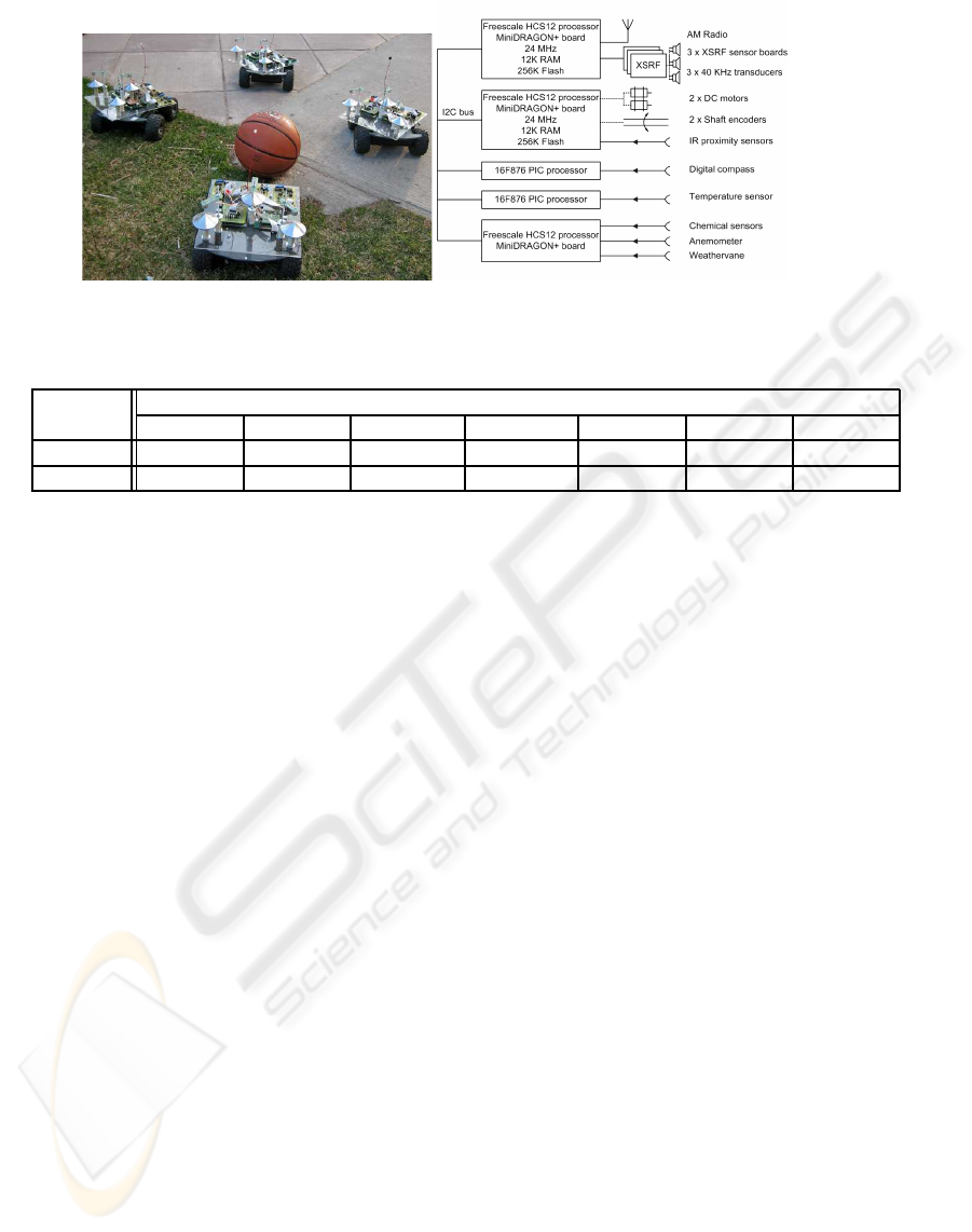
Figure 3: Maxelbots and the architecture.
Table 1: Mean and range of error of the followers’ X position at different distances and velocities.
Ideal Distance (cm)
Velocity
50 100 150 200 250 300 350
0.32 m/s 0.0 ± 0.2 0.3 ± 0.3 -0.3 ± 0.3 -0.6 ± 0.4 0.6 ± 0.5 1.9 ± 0.6 0.6 ± 0.6
0.64 m/s 0.0 ± 0.6 0.3 ± 0.3 -1.3 ± 0.9 -1.0 ± 1.0 1.0 ± 1.0 1.9 ± 1.1 0.0 ± 1.3
and 1). Above 3.5 m the acoustic signal is lost, be-
cause the acoustic energy falls below the threshold of
± 2 VDC and hence is not detected.
The mean error in X is very small (< 1%), which
means that the side-to-side position of the Maxelbot is
very close to the desired position. The mean error in
Y is larger, and at higher distances the Maxelbot lags
more behind the desired position (but the mean error
is < 5%). However, note that the range in error is less
at the higher velocity. The increased momentum of
the robot helps filter sensor noise.
7 OUTDOOR EXPERIMENTS
This section presents three experiments that test the
trilateration system outside. In particular, the Maxel-
bots are run in a region in the center of the University
of Wyoming campus. This region consists mostly of
grass, of average height 5 cm, interspersed with con-
crete sidewalks, trees, rocks, leaves, and other debris.
The grass hits the bottom of the Maxelbot. Although
generally flat, the ground slope can change rapidly
(within 0.6 m), by up to 20
◦
, at boundaries. Results
presented below are averaged over five independent
runs, each taken over a 20 minute interval. The speed
of the robots is approximately 0.55 m/s. For these ex-
periments we are forced to use the trilateration read-
ings themselves as an estimate to the quality of the
formation. Given the accuracy of the results in the
prior section, this is a reasonable and practical ap-
proach.
7.1 Accuracy of a Linear Formation
The first experiment has three Maxelbots in a linear
formation. The purpose of this experiment was to de-
termine the effect of having the middle robot occlude
the acoustic signal between the first and third Maxel-
bots. The first follower (middle robot) tries to keep
the leader at (0 cm, 63.5 cm) with respect to its local
coordinate system. The second follower tries to keep
the leader at (0 cm, 145 cm) with respect to its local
coordinate system.
Table 3 summarizes the quality of the results. This
first follower maintains position quite well. The sec-
ond follower does exhibit some difficulties due to oc-
clusion, since it does lag a bit behind the ideal dis-
tance. However, even in this case the distance is ap-
proximately only 10% off from the ideal distance.
Also, the standard deviation is acceptably low.
7.2 Accuracy of Non-Linear Formations
The second and third experiments examine the effect
of position with respect to the quality of the results
(trilateration accuracy can be affected by the differ-
ence in the bearing of one robot with respect to an-
other (Heil, 2004)). We try two different configura-
tions of the robots. In the first, there are three robots.
The right follower tries to keep the leader at (-48 cm,
91 cm) with respect to its local coordinate system.
The left follower tries to keep the leader at (53 cm,
91 cm) with respect to its local coordinate system. In
the second configuration we use four Maxelbots in a
diamond formation. In this latter experiment the wind
TRILATERATION LOCALIZATION FOR MULTI-ROBOT TEAMS
305
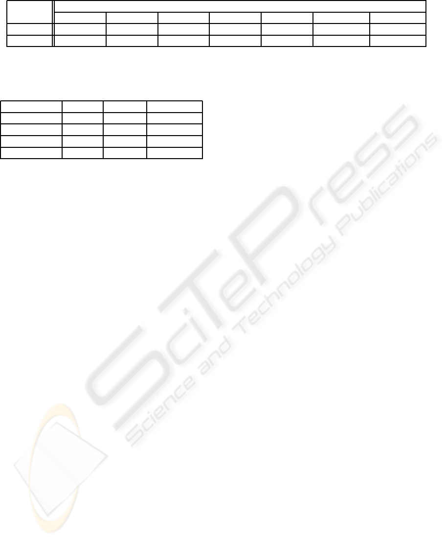
Table 2: Mean and range of error of the followers’ Y position at different distances and velocities.
Ideal Distance (cm)
Velocity
50 100 150 200 250 300 350
0.32 m/s -1.0 ± 1.6 0.0 ± 1.3 -1.3 ± 2.5 -1.9 ± 3.2 -1.3 ± 5.1 -5.0 ± 10.2 -5.0 ± 7.6
0.64 m/s -5.7 ± 0.6 -0.6 ± 1.9 -3.8 ± 2.5 -5.1 ± 3.8 -3.2 ± 4.4 -14.0 ± 3.8 -16.5 ± 3.8
Table 3: Accuracy of the two followers’ X and Y positions
in a linear formation (results in cm).
Ideal Mean Std. dev.
Follower1-X 0 -1.5 0.8
Follower1-Y 63.5 67.1 1.0
Follower2-X 0 0.3 4.8
Follower2-Y 145 159.8 4.1
speed near the ground ranged from 4 to 9 m/s.
Table 4 shows the XY-coordinates derived from
the trilateration readings, for both configurations.
From this table, it can be seen that the means are very
close to the ideal. The standard deviation is some-
what higher, reflecting the more difficult environmen-
tal conditions. However, very good formations are
maintained by the trilateration system despite ground
disturbances, wind, dust, and relatively high speed
(Y has at most an error of roughly 11%). Results
are averaged over five independent runs. Thus far no
position-dependent effects have been noticed (other
than distance, as is expected).
7.3 Trilateration Reliability Results
A detailed data analysis has been performed on the
reliability of the trilateration system during the out-
door experiments. The RF failure rate is 0.2%. The
rate at which the RF pulse is received but acoustic
pings are not received (at all three receivers) is only
1%. Almost every acoustic failure was isolated, and
not consecutive. Consider the interpretation of these
results. Given that acoustic pings are sent at a rate of
approximately four per second (4.17 Hz), this implies
that 1% of the time, the Maxelbots ran for only 0.25
seconds on old data. Only once were two consecutive
pings in a row not received, yielding one 0.5 second
gap in readings.
Of all of our tests, the factor most important to
success was the temperature. Below roughly 6
◦
C the
electronics failed. Given that our components are not
ruggedized, this is not surprising.
8 SUMMARY
This paper describes a 2D trilateration framework for
the fast, accurate localization of neighboring robots.
The framework uses three acoustic transducers and
one RF transceiver. Our framework is designed to be
modular, so that it can be used on different robotic
platforms, and is not restricted to any particular class
of control algorithms. Although we do not rely
on GPS, stationary beacons, or environmental land-
marks, their use is not precluded. Our framework is
fully distributed, inexpensive, and scalable.
To illustrate the general utility of our framework,
we demonstrated the application of our new robots
in outdoor situations. The results from these ex-
periments highlight the accuracy of our trilateration
framework, as well as its current limitations (range
and environmental temperature). For all of the Maxel-
bots, their X and Y positions are within roughly 11%
of the desired values.
Open Source Project URL
The open source URL http://
www.cs.uwyo.edu/∼wspears/maxelbot provides
schematic details and videos of this project. We thank
the Joint Ground Robotics Enterprise for funding
portions of this work.
REFERENCES
Balch, T., Hybinette, M.: Social potentials for scalable mul-
tirobot formations. In: IEEE Transactions on Robotics
and Automation. Volume 1. (2000) 73–80
Fax, J., Murray, R.: Information flow and cooperative con-
trol of vehicle formations. IEEE Transactions on Au-
tomatic Control 49 (2004) 1465–1476
Fierro, R., Song, P., Das, A., Kumar, V.: Cooperative
control of robot formations. In Murphey, R., Parda-
los, P., eds.: Cooperative Control and Optimization.
Volume 66., Hingham, MA, Kluwer Academic Press
(2002) 73–93
Brogan, D., Hodgins, J.: Group behaviors for systems with
significant dynamics. Autonomous Robots 4 (1997)
137–153
ICINCO 2008 - International Conference on Informatics in Control, Automation and Robotics
306
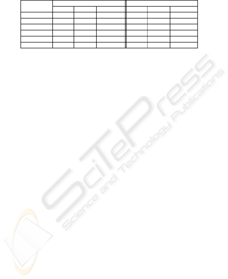
Table 4: Accuracy of the followers’ X and Y positions in a both formations (results in cm).
Triangle Diamond
Ideal Mean Std. dev. Ideal Mean Std. dev
Follower1-X -48 -53.0 3.3 61 62.2 1.8
Follower1-Y 91 97.8 2.8 61 54.9 2.8
Follower2-X 53 57.2 4.8 -61 -64.3 4.3
Follower2-Y 91 96.0 3.6 61 54.7 3.6
Follower3-X - - - 0 1.0 5.1
Follower3-Y - - - 122 111.8 4.6
Spears, W., Spears, D., Hamann, J., Heil, R.: Distributed,
physics-based control of swarms of vehicles. Au-
tonomous Robots 17(2-3) (2004)
Borenstein, J., Everett, H., Feng, L.: Where am I? Sensors
and Methods for Mobile Robot Positioning. Univer-
sity of Michigan (1996)
Thomas, F., Ros, L.: Revisiting trilateration for robot local-
ization. IEEE Transactions on Robotics 21(1) (2005)
93–101
Peasgood, M., Clark, C., McPhee, J. Localization of multi-
ple robots with simple sensors. In: IEEE/RSJ Interna-
tional Conference on Intelligent Robots and Systems
(IROS’05). (2005) 671–676
MacArthur, D.: Design and implementation of an ultrasonic
position system for multiple vehicle control. Master’s
thesis, University of Florida (2003)
Nissanka, B., P.: The cricket indoor location system. Doc-
toral thesis, Massachusetts Institute of Technology,
Cambridge, MA (2005)
Navarro-Serment, L., Paredis, C., Khosla, P.: A beacon sys-
tem for the localization of distributed robotic teams.
In: International Conference on Field and Service
Robots, Pittsburgh, PA (1999) 232–237
Rothermich, J., Ecemis, I., Gaudiano, P.: Distributed local-
ization and mapping with a robotic swarm. In S¸ahin,
E., Spears, W., eds.: Swarm Robotics, Springer-Ve
rlag (2004) 59–71
Payton, D., Estkowski, R., Howard, M.: Pheromone
robotics and the logic of virtual pheromones. In S¸ahin,
E., Spears, W., eds.: Swarm Robotics, Springer-
Verlag (2004) 46–58
Spears, W., Hamann, J., Maxim, P., Kunkel, T., Heil, R.,
Zarzhitsky, D., Spears, D., Karlsson, C. Where are
you? In S¸ahin, E., Spears, W., eds.: Swarm Robotics,
Springer-Verlag (2006)
Heil, R.: A trilaterative localization system for small mo-
bile robots in swarms. Master’s thesis, University of
Wyoming, Laramie, WY (2004)
Zarzhitsky, D., Spears, D., Spears, W.: Distributed robotics
approach to chemical plume tracing. In: IEEE/RSJ In-
ternational Conference on Intelligent Robots and Sys-
tems (IROS’05). (2005) 4034–4039
Hettiarachchi, S.: Distributed evolution for swarm robotics.
Ph.D. thesis, University of Wyoming, Laramie, WY
(2007)
TRILATERATION LOCALIZATION FOR MULTI-ROBOT TEAMS
307
