
A BIOLOGICALLY INSPIRED HARDWARE MODULE FOR
EMBEDDED AUDITORY SIGNAL PROCESSING APPLICATIONS
Xin Yang, Mokhtar Nibouche, Tony Pipe and Chris Melhuish
Bristol Robotics Laboratory, University of the West of England, Coldharbour Lane, Bristol, U.K.
Keywords:
Bio-inspired system, Auditory subsystems, Acoustic signal processing, Digital filter, FPGA, System on chip.
Abstract:
This paper presents a fully parameterised and highly scalable design prototype of FPGA (field programmable
gate array) implementation of a biologically inspired auditory signal processing system. The system has
been captured and simulated using system-level integrated design tools, namely, System Generator
TM
and
AccelDSP
TM
both from Xilinx
TM
. The implemented hardware auditory periphery model consists of two
sub-models—the Patterson’s Gammatone filter bank and the Meddis’ inner hair cell. The prototype has been
successfully ported onto a Virtex
TM
–II Pro FPGA. Ultimately, it can be used as a front-end apparatus in a
variety of embedded auditory signal processing applications.
1 INTRODUCTION
The human peripheral auditory system, as illustrated
in Figure 1, consists of the outer, middle and inner ear.
The inner ear, or the cochlea, is a coiled tube filled
with fluid. The sound vibration is transmitted to the
fluid, and then to the basilar membrane of the cochlea.
The stiffness of the basilar membrane decreases expo-
nentially along the length of the cochlea. This makes
the basilar membrane act like a frequency analyser
with the base part (near the oval window) responding
to high frequencies, and the apical part (the far end)
responding to lower frequencies. The sensory cells to
detect the frequencies are the hair cells attached to the
basilar membrane. There are three rows of outer hair
cells (OHC) and one row of inner hair cells (IHC).
For human, there are approximately 12,000 OHCs
and 3,500 IHCs (Truax, 1999). The movement of the
OHCs and the basilar membrane is conveyed to the
IHCs and causes a depolarisation, which in turn re-
sults in a receptor potential. Thus, IHCs release neu-
rotransmitters, whose concentration change gives rise
to nerve spikes into the auditory nerve.
The human auditory system deals with a wide
range of everyday real life applications such as pitch
detection, sound localisation and speech recognition,
just to name few. It does the job extremely well, and
far better than the current acoustic sensor technology
based systems. The auditory system consists of the
auditory periphery, as the front end sensing apparatus,
and includes different other regions of the brain up to
Figure 1: The human ear (Truax, 1999).
the auditory cortex. The auditory periphery ’trans-
duces’ acoustical data into train of spikes for more
high level neuronal processing. Based on this, many
researchers and engineers believe that modelling and
implementation of an artificial auditory subsystems,
especially the cochlea, will yield better performance
in acoustic signal processing. The reported electronic
cochlea implementations fall into two categories.
One is the task-oriented engineering approach,
which treats the whole cochlea as filters in order to
obtain the time/frequency information that can be
used for different kinds of post-processing. These
are the majority of the reported implementations, in-
cluding the first electronic cochlea proposed by Lyon
and Meads (Lyon and Mead, 1988), some recent
FPGA implementations (Mishra and Hubbard, 2002),
(Leong et al., 2003), and (Wong and Leong, 2006).
The other category is the research-oriented signal
382
Yang X., Nibouche M., Pipe T. and Melhuish C. (2009).
A BIOLOGICALLY INSPIRED HARDWARE MODULE FOR EMBEDDED AUDITORY SIGNAL PROCESSING APPLICATIONS.
In Proceedings of the International Conference on Bio-inspired Systems and Signal Processing, pages 382-387
DOI: 10.5220/0001554703820387
Copyright
c
SciTePress

processing approach, which analyses each stage of the
biological acoustic signal processing in the auditory
neurological system. There is less work in this cat-
egory, and most of them focus on the hair cells and
auditory nerve. Lim reported a pitch detection sys-
tem (Lim et al., 1997) based on the Meddis’ inner
hair cell model (Meddis, 1986), then Jones improved
it to a four-stage pitch extraction system (Jones et al.,
2000). A spike-based sound localisation system was
implemented by Ponca (Ponca and Schauer, 2001).
There was an analogue hair cell model implemented
and then improved by van Schaik (van Schaik and
Meddis, 1999), (van Schaik, 2003).
The prototype implementation of the auditory sub-
system in this paper belongs to the second cate-
gory. It models a part of the signal processing
of the human cochlea, by connecting two widely
accepted models, the Patterson’s Gammatone filter
bank (GFB) (Patterson et al., 1992) and the Meddis’
inner hair cell (IHC) (Meddis, 1986). Compared to
other existing work, the proposed hardware imple-
mentation is fully parameterised and highly scalable.
It provides a good platform for further research, and
can be developed at the front-end of an embedded au-
ditory signal processing system.
2 PATTERSON’S GAMMATONE
FILTER BANK
The GFB proposed by Patterson (Patterson et al.,
1992) is a set of parallel Gammatone filters, each of
which responds to a specific frequency range. The
Gammatone filter is a bandpass filter with gamma dis-
tribution well known in statistics. It describes the
impulse response of a cat’s cochlea, which is very
similar to the human cochlea. The GFB provides a
reasonable trade-off between accuracy in simulating
the basilar membrane motion and computational load.
Some improved models have been developed based
on the original work, however, due to the increased
hardware computation burden, the original model is
adapted here. The impulse response of a Gammatone
filter is:
h(t) = At
N−1
e
−2πbt
cos(2π f
c
t + ϕ) (t ≥0, N ≥1)
(1)
Where A is an arbitrary factor that is typically used
to normalise the peak magnitude to unity; N is the fil-
ter order; b is a parameter that determines the duration
of the impulse response and thus the filters bandwidth,
f
c
is the centre frequency, and ϕ is the phase of the
tone.
Slaney developed a digital version of the GFB
(Slaney, 1993), then implemented it in his famous
Matlab
TM
“Auditory Toolbox” (Slaney, 1998). Each
digital Gammatone filter consists of four second-
order sections (SOS) or Infinite Impulse Response
(IIR) filters, as illustrated in Figure 2. The general
Z transfer function for each IIR filter is:
H(z) =
A
0
+ A
1
z
−1
+ A
2
z
−2
1 + B
1
z
−1
+ B
2
z
−2
(2)
SOS
1
Gammatone Filter Bank Channel 1
SOS
2
SOS
3
SOS
4
SOS
1
Gammatone Filter Bank Channel 2
SOS
2
SOS
3
SOS
4
In Out 1
Out 2
Out N
.
.
.
.
.
.
.
.
.
.
.
.
.
.
.
SOS
1
Gammatone Filter Bank Channel N
SOS
2
SOS
3
SOS
4
Figure 2: Slaney’s digital Gammatone filter bank.
3 MEDDIS’ INNER HAIR CELL
MODEL
Meddis introduced the first hair cell model (Med-
dis, 1986), which describes the transduction between
IHCs and auditory nerves in a manner quite close to
physiology by modelling both the short term and long
term adaptation characteristics of the IHCs. Just like
the case of the GFB model, the Meddis’ IHC model
has also been improved to adapt new findings in bi-
ology, however, for simplicity, the original model is
chosen for this prototype implementation. The Med-
dis’ IHC model can be described by a set of four non-
linear equations (Meddis, 1986).
k(t) =
(
g(s(t)+A)
s(t)+A+B
for s(t) + A > 0
0 for s(t) + A ≤ 0
(3)
dq
dt
= y(1 −q(t)) + rc(t) −k(t)q(t) (4)
dc
dt
= k(t)q(t) −lc(t) −rc(t) (5)
P(e) = hc(t)dt (6)
Where k(t) is the permeability; s(t) is the instan-
taneous amplitude; q(t) is the cell transmitter level;
A BIOLOGICALLY INSPIRED HARDWARE MODULE FOR EMBEDDED AUDITORY SIGNAL PROCESSING
APPLICATIONS
383

P(e) is the spike probability; A, B, g, y, l, x, r and m
are constants based on statistics; and h is the propor-
tionality factor, which can be set to different values.
The underlying structure of the model is illus-
trated in Figure 3 (Meddis, 1986). It is worth not-
ing that there is also a Matlab
TM
implementation of
the Meddis’ IHC model in Slaney’s “Auditory Tool-
box” (Slaney, 1998), which provides a reference for
this design prototype.
Figure 3: The Meddis’ inner hair cell model (Meddis,
1986).
4 SYSTEM IMPLEMENTATION
4.1 System Architecture
The proposed system architecture, as illustrated in
Figure 4, consists of a GFB (a set of Gammatone fil-
ters) that mimics the behaviour of the basilar mem-
brane, interfaced in a parallel fashion to the Med-
dis’ IHC module through a bank of buffers. Each
Gammatone filter is combined with a single Med-
dis’ IHC to process for a particular range of fre-
quencies (double-lined circle in Figure 4). The GFB
(basilar membrane module) processes the incoming
signal using parallel channels for different frequency
ranges, and generates outputs that represent the vi-
bration displacements along different parts of the bi-
ological basilar membrane. The Meddis’ IHC mod-
ule calculates the probability rate of neural spikes
(spikes/second) corresponding to each output gener-
ated by the GFB module. A channel structure con-
sisting of a Gammatone filter, a buffer and an IHC
(double-lined circle in Figure 4) could be reconfig-
ured to implement any of the system channels (1, 2,
3, . . . , n, . . . , N) through parameterisation. The sys-
tem is also scalable, which means that an arbitrary
number of channels can be generated, again through
parameterisation. Simulation can be carried out either
in software or hardware, however, for this prototyping
stage; software simulation is preferred.
The specifications of the complete model are as
follows. First, the “audible” frequency range of the
basilar membrane module has to cover the human au-
ditory range—from 200 Hz to 20 kHz (Truax, 1999).
A direct consequence is that the sampling frequency
of the system sets to 44 kHz to allow a reasonable
discrete representation. Second, perhaps a little arbi-
trarily, the number of channels is set to 20. Although
the number of GFB channels should be the same as
the number of IHCs in the cochlea (3,500), a com-
promise has to be made because of the constraints on
hardware. Finally, the system must operate in real-
time.
The general design methodology relies predomi-
nantly on IP-based blocks to model DSP primitives
such as adders and multipliers using signed fixed-
point bit serial arithmetic. Appropriate number repre-
sentation, quantisation and overflow handling of the
signals in the system are keys for a successful imple-
mentation. As such, the system input was coded as
14-bit signed fixed-point numbers, with 12 fractional
bits. The output of the basilar membrane module was
reduced to 10 bits with 8 fraction bits to relieve the
computation load for the Meddis inner hair cell mod-
ule. The output of the system was set as 14-bit with
12 fractional bits, in a similar fashion to the input.
Input
Signal
Out 1
Out 2
Out n
Basilar
Membrane
Module
.
.
.
.
.
.
.
.
.
Gammatone
Filter n
Buffer
Meddis n
Gammatone
Filter 1
Buffer
Meddis 1
Gammatone
Filter 2
Buffer
Meddis 2
Gammatone
Filter N
Buffer
Meddis N
.
.
.
.
.
.
.
.
.
Meddis
Inner Hair
Cell Module
Out N
Implementation
N: total number of channels
n: channel number
Figure 4: Structure for the whole model and the imple-
mented channel.
4.2 Basilar Membrane Module
For the proposed design prototype, only one chan-
nel of the GFB was implemented using Sys-
tem Generator
TM
(Xilinx, 2008b). A channel or a
Gammatone filter consists of four second-order IIR
filters (SOS), each of which is implemented in the
direct form structure, as illustrated in Figure 5. The
calculations of the SOSs’ coefficients are achieved
by using Slaney’s “Auditory Toolbox”. There is no
BIOSIGNALS 2009 - International Conference on Bio-inspired Systems and Signal Processing
384
A
2
forward path as indicated in the transfer function
of equation 2, simply because the coefficient A
2
is
always zero for all the SOSs of any channel. The
numerator coefficients (A
0
and A
1
) of each SOS are
scaled by
4
√
total gain, resulting in the Gammatone
filter to be scaled by the total gain which is calcu-
lated by the toolbox. This scaling narrows the dy-
namic range of the intermediate signals, and results
in a reduced word length for the adders and multipli-
ers. Table 1 presents an example of the calculated co-
efficients for the first channel of the GFB, where the
total gain for this channel is 2.90294 ×10
16
. Conse-
quently, all the coefficients A
0
and A
1
in the table are
scaled by 1.30529 ×10
4
. It is worth noting that only
the coefficient A
1
of the a SOS differ from those of
the other 3 SOSs in the same channel, which makes a
hardware optimisation possible for a single SOS.
+
x
Z
-1
A
0
A
1
-B
1
-B
2
x
x
x+
+
Z
-1
Figure 5: A second-order section of the Gammatone filter.
Table 1: Coefficients of the IIR filters in channel 1.
IIR A
0
A
1
B
1
B
2
SOS 1 0.29665−0.10187 1.26532 0.56372
SOS 2 0.29665 0.47724 1.26532 0.56372
SOS 3 0.29665 0.13800 1.26532 0.56372
SOS 4 0.29665 0.23736 1.26532 0.56372
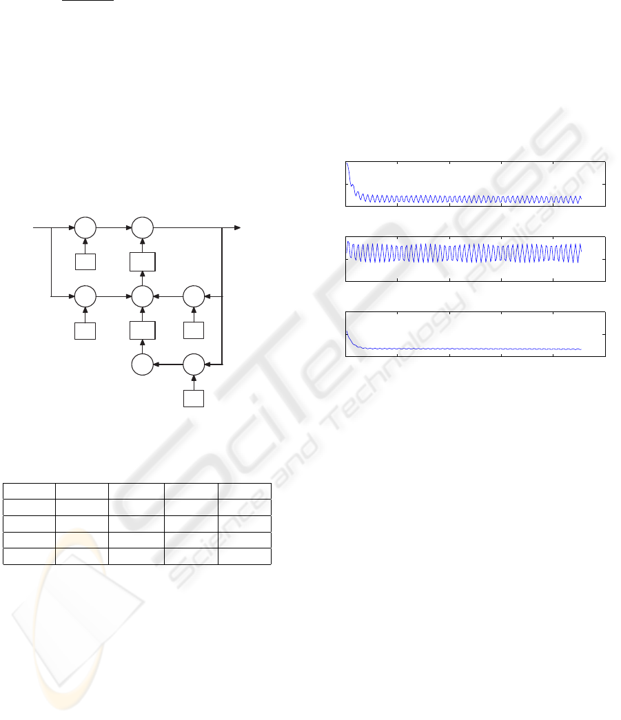
4.3 Meddis Inner Hair Cell Module
Slaney’s Matlab
TM
implementation (Slaney, 1998) of
the Meddis’ IHC model must be revised prior to be
synthesised by AccelDSP
TM
(Xilinx, 2008a). This is
not only because of the constraint requirements im-
posed by the AccelDSP
TM
software, but also the de-
mand for a real-time DSP system. The revised imple-
mentation processes the input signal in a fixed-point,
bit-serial fashion, which leads to an unavoidable er-
ror compared to the original floating-point model,
as illustrated in Figure 6. The investigation into
the reported hardware implementation ((Lim et al.,
1997),(Jones et al., 2000)) highlights this error as
well. In reality, this is not a critical issue since the ex-
act numerical values of the probability spike rate out-
put are not essential for the spike generation (could be
scaled up using the h coefficient in equation 6), how-
ever, the half-wave rectification, the saturation and the
adaptation (both long term and short term) character-
istics of the output are in return quite important (Jones
et al., 2000). The Meddis IHC module was generated
based on this revised model using AccelDSP
TM
. Fig-
ure 6 gives a comparison between the generated fixed-
point model and the original floating-point model us-
ing a 1 kHz sine wave input.
0 1 2 3 4 5
x 10
−3
0.5
0.6
0.7
0 1 2 3 4 5
x 10
−3
0.65
0.7
0 1 2 3 4 5
x 10
−3
−0.2
0
0.2
Simulation Time (s)
Firing Rate (spikes/s)
Figure 6: From top to bottom: outputs of the fixed-point
Meddis’ IHC model, the floating-point Meddis’ IHC model
and the error, with 1 kHz sine wave input.
4.4 Simulation and Synthesis Results
The test bench illustrated in Figure 7 was built to com-
pare the simulation results of the original Matlab
TM
floating-point model, the System Generator
TM
fixed-
point model and the FPGA hardware implementation
model, however, the simulation here are only carried
out in software at this prototyping stage. The input
signal is generated by Simulink
TM
blocks and can
also be imported from files or even real-time external
events. By an initialisation script, the total number
of channels of the auditory subsystem can be set to
an arbitrary number, in this case, 20, and the fixed-
point model can be configured as anyone of the chan-
nels. The simulation results, shown in Figure 8, de-
picts the outputs of the 5
th
channel under considera-
tion for a step and then a sine wave input functions
respectively. The hardware model generates closely
matched outputs comparing with that of the software
implementation in the simulation. The synthesis re-
port illustrated in Table 2 indicates that the hardware
utilisation is quite low (7%), except for the multipli-
A BIOLOGICALLY INSPIRED HARDWARE MODULE FOR EMBEDDED AUDITORY SIGNAL PROCESSING
APPLICATIONS
385

ers (32%), but the design can run in real-time. It also
implies that only 3 channels can be implemented in
parallel for this FPGA chip.
Table 2: Synthesis report of the first channel of the auditory
subsystem.
Target Device XC2VP30
Synthesis Tool XST v10.1.01
Used Slices 993 7%
Used Slice Flip Flops 827 3%
Used 4 input LUTs 2,574 9%
Used RAMB16s 2 1%
Used MULT18X18s 44 32%
Max Frequency 17.505 MHz
5 CONCLUSIONS AND FUTURE
WORK
The paper presents the design and FPGA implemen-
tation of a bio-inspired hardware module that can be
used as a front end apparatus in a variety of embedded
auditory signal processing applications. The imple-
mentation consists of two sub-modules, Patterson’s
GFB and Meddis’ IHC, linked together to mimic the
behaviour of a single frequency channel of the audi-
tory periphery. The proposed design is fully param-
eterised and highly scalable. The design prototype
has been captured and then simulated using two inte-
grated tools, System Generator
TM
and AccelDSP
TM
both from Xilinx
TM
. The prototype works as ex-
pected and the design process is much faster than
the traditional hardware description language (HDL)
design flow. The resulting hardware structure was
too large to accommodate a 20-channel parallel au-
ditory subsystem; therefore, a time-shared multiplex-
ing scheme is envisaged for future implementations.
More optimisation can be achieved for the filter mod-
ules to improve the system performance and reduce
the number of multipliers. The ultimate goal is to
build a complete bio-inspired system that models the
signal processing of the whole human auditory sys-
tem.
REFERENCES
Jones, S., Meddis, R., Lim, S., and Temple, A. (2000). To-
ward a digital neuromorphic pitch extraction system.
Neural Networks, IEEE Transactions on, 11(4):978–
987.
Leong, M. P., Jin, C. T., and Leong, P. H. W. (2003). An
fpga-based electronic cochlea. EURASIP Journal on
Applied Signal Processing, 2003:629–638.
Lim, S., Temple, A., Jones, S., and Meddis, R. (1997).
Vhdl-based design of biologically inspired pitch de-
tection system. In Neural Networks,1997., Interna-
tional Conference on, volume 2, pages 922–927.
Lyon, R. and Mead, C. (1988). An analog electronic
cochlea. Acoustics, Speech, and Signal Processing
[see also IEEE Transactions on Signal Processing],
IEEE Transactions on, 36(7):1119–1134.
Meddis, R. (1986). Simulation of mechanical to neural
transduction in the auditory receptor. Journal of the
Acoustical Society of America, 79(3):702–711.
Mishra, A. and Hubbard, A. (2002). A cochlear filter imple-
mented with a field-programmable gate array. Circuits
and Systems II: Analog and Digital Signal Processing,
IEEE Transactions on [see also Circuits and Systems
II: Express Briefs, IEEE Transactions on], 49(1):54–
60.
Patterson, R. D., Robinson, K., Holdsworth, J., McKeown,
D., Zhang, C., and Allerhand, M. (1992). Complex
sounds and auditory images. In Cazals, Y., Demany,
L., and Horner, K., editors, Auditory Physiology and
Perception, page 429C446. Pergamon, Oxford.
Ponca, M. and Schauer, C. (2001). Fpga implementation
of a spike-based sound localization system. In 5th In-
ternational Conference on Artificial Neural Networks
and Genetic Algorithms - ICANNGA2001.
Slaney, M. (1993). An efficient implementation of the
patterson-holdsworth auditory filter bank. Technical
Report 35, Perception GroupłAdvanced Technology
Group, Apple Computer.
Slaney, M. (1998). Auditory Toolbox.
Truax, B., editor (1999). HANDBOOK FOR ACOUSTIC
ECOLOGY. Cambridge Street Publishing, 2 edition.
van Schaik, A. (2003). A small analog vlsi inner hair cell
model. In Circuits and Systems, 2003. ISCAS ’03.
Proceedings of the 2003 International Symposium on,
volume 1, pages 17–20.
van Schaik, A. and Meddis, R. (1999). Analog very large-
scale integrated (vlsi) implementation of a model
of amplitude-modulation sensitivity in the auditory
brainstem. Journal of the Acoustical Society of Amer-
ica, 105:811–821.
Wong, C. K. and Leong, P. H. W. (2006). An fpga-based
electronic cochlea with dual fixed-point arithmetic. In
Field Programmable Logic and Applications, 2006.
FPL ’06. International Conference on, pages 1–6.
Xilinx (2008a). AccelDSP User Guide. Xilinx, 10.1.1 edi-
tion.
Xilinx (2008b). System Generator for DSP User Guide.
Xilinx, 10.1.1 edition.
BIOSIGNALS 2009 - International Conference on Bio-inspired Systems and Signal Processing
386

Figure 7: Test bench for the simulation of the prototype implementation of the auditory subsystem.
Figure 8: Simulation results for the 5
th
channel. (a) the output of the basilar membrane module with step input; (b) the output
of the basilar membrane module with 1 kHz sine input; (c) the output of the Meddis IHC module with step input; (d) the
output of the Meddis IHC module with 1 kHz sine input. For each sub-figure, the output of the fixed-point hardware model
is at the top, the output of the floating-point software module is in the middle, and the calculated error is at the bottom. The
X-axis represents the simulation time, and the Y-axis represents the amplitude of the output.
A BIOLOGICALLY INSPIRED HARDWARE MODULE FOR EMBEDDED AUDITORY SIGNAL PROCESSING
APPLICATIONS
387
