
EFSAT
An Exact and Efficient Triangle Intersection Test Hardware
Andreas Raabe, Jan Tietjen and Joachim K. Anlauf
Technical Computer Science, University of Bonn, R
¨
omerstr. 164, 53117 Bonn, Germany
Keywords:
Intersection test, Hardware acceleration, Fixed-point, Exact.
Abstract:
Software implementations that test two triangles for intersection often favour speed over exact calculation.
They leave it to the user to choose an exact or a fast test depending on the domain of application. Hardware
implementations can not opt to make this distinction since users will always expect an accelerator hardware
to be applicable in all possible settings. This paper introduces a novel approach towards exact intersection
testing of triangles. It is based on the separating axes test and lends itself well to hardware implementation.
To be integrable into a hierarchical collision detection design this test needs to be extremely resource efficient.
Thus, it does not iterate until an exact solution is found, but instead categorises results as correct and possi-
bly incorrect. It is implemented using 18-bit fixed-point numbers, while still maintaining resolutions that can
keep up with double-precision floating-point implementations. The proposed test is integrated into a hierar-
chical collision detection FPGA-design accelerating collision queries by an order of magnitude. In a realistic
benchmark less than 0.9% of possibly incorrect results are reported without impairing system performance.
1 INTRODUCTION
In physically-based simulation most of the process-
ing effort is spent on collision detection (Plante et al.,
2001). Hence hardware acceleration of collision
queries significantly speeds-up the overall simulation
and liberates the CPU for other tasks. Since surfaces
are often composed of triangles, a last step in process-
ing the query is usually intersection testing of triangle
pairs. When using hierarchical or spacial subdivision
approaches only a relatively small number of triangles
will be singled out for testing. This and the concur-
rent processing of the hierarchy renders the overall
performance independent of the delay of the triangle
intersection test. Still, it is highly beneficial to imple-
ment it in hardware as well, since it will reduce the
number of triangles transferred back to the host. This
reduces the delay caused by bus transfers which has
significant impact on overall performance.
Software implemented algorithms for testing two
triangles for intersection often favor speed over ex-
act calculation. Examples for this are the well known
intersection tests of Held (Held, 1996) and M
¨
oller
(M
¨
oller, 1997). They leave it up to the user to choose
an exact or a fast test depending on the domain of ap-
plication. Hardware implementations can not opt to
make this distinction since users will always expect an
accelerator hardware to be applicable in all possible
settings. Known approaches for exact collision detec-
tion, on the other hand, are usually iterative in nature.
In general this iterativeness arises through the use of
arbitrary precision libraries like CORE (Karamcheti
et al., 1999) or LEDA (Mehlhorn and Schirra, 2001)
in standard algorithms like the ones stated above.
This renders every arithmetic operation a potential it-
eration over the necessary precision. (Robbins and
Whitesides, 2003) uses Shewchuk’s orientation test
(Shewchuk, 1997) in combination with M
¨
oller’s in-
tersection test. This is more elegant, since it solely
needs to iterate the calculation of the 3D orientation
predicate given as the sign of a polynomial of de-
gree 3 in the coordinate values of four points. A well
known fact in hardware development is that unrolling
iterative algorithms renders them very resource con-
suming. Since in general one will want to operate
the triangle intersection concurrently to a hierarchy
or a spatial subdivision traversal, they both need to
be small to fit into the same chip. This avoids addi-
tional delay caused by inter-chip communication. A
very fast and yet hardware efficient hierarchical col-
lision detection architecture based on k-DROPs was
proposed by (Raabe et al., 2006). It is also provably
exact, thus it does not return any false reports of non-
collision. It will be used in the following as a basis
and the proposed exact intersection test will be inte-
355
Raabe A., Tietjen J. and K. Anlauf J. (2009).
EFSAT - An Exact and Efficient Triangle Intersection Test Hardware.
In Proceedings of the Fourth International Conference on Computer Graphics Theory and Applications, pages 355-360
DOI: 10.5220/0001775203550360
Copyright
c
SciTePress

grated into the overall design. Usage of hierarchical
intersection test yields a logarithmic average run-time
in realistic scenarios (Weller et al., 2006). An AABB
based broad-phase collision test was implemented in
hardware in (Woulfe et al., 2007). It could be applied
prior to the hierarchy traversal in future implementa-
tions.
2 EFSAT
2.1 Separating Axes Test
The separating axes approach as proposed in
(Gottschalk, 1996) tests two convex polytopes for in-
tersection by projecting them onto a set of test axes. If
the projections do not intersect it follows that the axis
is the normal of a plane separating the polytopes. If
neither any normal of any of the faces, nor any cross
products of edges of both polytopes are a separating
axis then the polytopes intersect.
Triangles can be interpreted as degenerated poly-
topes in 3D and thus the SAT approach can be applied
to them. Let
e
A and
e
B be two triangles. In general
e
A
and
e
B will life in different reference frames (RFs). To
test them for intersection, we need to transform them
into a common RF. Let this common RF be that of
e
A without loss of generality and let M be the accord-
ing transformation matrix. Let the resulting triangles
be B (with vertices W
0
, W
1
, and W
2
) and A =
e
A (with
vertices V
0
, V
1
, and V
2
).
Using around indexing, the normals n
A
, n
B
and the
cross products C
k,l
can now be calculated as follows.
n
A
:= (V
1
−V
0
) ×(V
2
−V
0
)
n
B
:= (W
1
−W
0
) ×(W
2
−W
0
)
C
k,l
:= (V
k+1
−V
k
) ×(W
l+1
−W
l
)
(1)
Then the triangles’ points are projected onto any test
axis L out of this set by
p
V
k
:= V
k
∗L p
W
l
:= W
l
∗L (2)
The projection intervals on the axis are
I
A
:= [min
{
p
V
0
, p
V
1
, p
V
2
}
, max
{
p
V
0
, p
V
1
, p
V
2
}
]
I
B
:= [min
{
p
W
0
, p
W
1
, p
W
2
}
, max
{
p
W
0
, p
W
1
, p
W
2
}
]
(3)
If I
A
and I
B
do not intersect a separating axis
is found. It follows that the triangles are non-
intersecting. If none of the axes is separating the tri-
angles do intersect.
This test lends itself well to resource efficient
hardware implementation as was discussed in (Raabe
et al., 2008). The structure of this non-exact test
serves as a basis for the exact intersection test EFSAT
proposed in the following.
2.2 Pre-Processing
This calculation will (of course) not be computation-
ally exact if it is implemented using fixed-point or
floating-point types. Thus the images resulting from
the projections will differ from the mathematically
correct image. Size and sign of the error depend
on the size of the numbers and the rounding mode
used for arithmetic operations (e.g., IEEE floating-
point arithmetic defaults to rounding 0.0001 to 0.00
(error= 0.0001), and 0.001 to 0.01 (error= −0.001)).
To enable use of fixed-point data types it is im-
perative to normalize the objects to prevent a tremen-
dous loss of precision. Thus, all triangles are nor-
malized relatively to the size of the biggest one. To
enable bounding of all subsequent calculations as-
sume that a hierarchical bounding-volume test was
executed prior to the triangle intersection test. We are
using k-DROPs as bounding-volumes, and thus obtain
2
√
3 as a bound on the maximum distance of triangles
fed into the intersection test. Thus, numbers with 4-
bit integral digits are used. Any other bound will work
as well.
2.3 Fixed Point Interval Arithmetic
An obvious solution is using an arbitrary precision
datatype. As previously discussed this is very re-
source consuming when implemented in hardware.
Therefore we choose not to provide an exact solu-
tion for every query, but to categorize the results in
exact and possibly incorrect. Due to the grave space
restriction imposed by the FPGA-implementation we
use fixed-point arithmetic, and exploit that we have
complete control over the rounding modes and bit
width of the numbers.
Let a
n,k
be a fixed-point number of length n, of
which the k most significant bits are the integral part
of the number. m := n −k is the number of fractional
bits. Let ⊕ furthermore denote bit concatenation and
let a ∈ R, −2
k−1
≤ a < 2
k−1
−1. Now let ba
n,k
c be
the next smaller or equal fixed-point number of the
given dimensions and da
n,k
e be the next greater one.
The fixed-point resolution is then given by
EPS
n,k
:= da
n,k
e−ba
n,k
c = 0. 0 ···0
|{z}
m−1
1 (4)
Now we can initialize fixed-point intervals, so that
they contain the input data.
A
n,k
(a) :=
h
A
n,k
, A
n,k
i
=
h
ba
n,k
c, da
n,k
e
i
(5)
GRAPP 2009 - International Conference on Computer Graphics Theory and Applications
356
L
mathematically
correctprojection
maximumprojection
minimumprojection
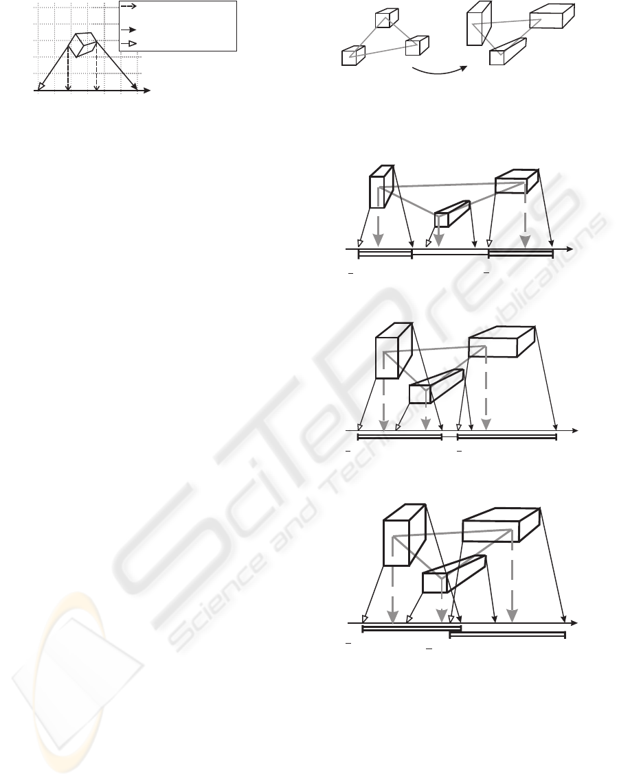
Figure 1: The actual projection using interval arithmetic can
be interpreted as a projection of the point intervals onto the
original axis. Then the minimum projection is underesti-
mated and the maximum projection is overestimated.
If this is done to all coordinates of a triangle point the
resulting intervals can be visualized as a cube aligned
with the discretization grid induced by the fixed-point
data-type.
Now operators ⊗ ∈
{
+, ·, −
}
can be defined on
intervals in a way, that the resulting interval contains
all possible outcomes of applying the operation to any
pair of numbers out of the intervals. Since linear op-
erators are used exclusively these operations can be
implemented very resource efficient using case dis-
crimination based on the signs of the interval bounds.
Since this is simple, but a bit lengthy it is left out
here. To prevent intermediate results from becoming
to large in bit-length they are reduced to the original
bit-length by rounding. This is easily done by round-
ing towards −∞ and, if it is supposed to be an upper
limit EPS
n,k
of the target type is added.
Now the projection 2 is applied to the interval
points using these interval operators and a test axis
also described using intervals. This can geometri-
cally be interpreted as a projection onto the original
test axis where the projection of the maximum possi-
ble value of the point will be overestimated to avoid
rounding errors. The minimum value will be underes-
timated accordingly. 1 illustrates this.
2.4 Testing Interval Images for
Intersection
After applying the previously discussed data types
and operators, the points of the triangles can be pro-
jected using interval arithmetic. Since again intervals
result it is no longer clear, how they need to be trans-
formed into images. Therefore it is necessary to ge-
ometrically interpret the presented algorithm.
Consider 2. Initializing the fixed-point intervals with
point coordinates will turn the points into cubes of
EPS
n,k
side length. Transforming triangle B into A’s
reference frame will turn those cubes into cuboids,
whose side lengths depend on the absolute values of
the original coordinates and of the matrix entries. The
actual projection of these cuboids results in a mini-
mum and a maximum projection each. From these we
Figure 2: Transforming one triangle into the reference
frame of the other using fixed-point numbers contributes to
the derivation from the mathematically correct result. This
is respected in the size of the coordinate intervals.
L
mightbe
occupied
occupied
mightbe
occupied
a
min
a
max
a
min
a
max
_
_
(a)
L
mightbe
occupied
occupied
mightbe
occupied
a
min
a
max
a
min
a
max
_
_
(b)
L
mightbe
occupied
mightbe
occupied
a
min
a
max
a
min
a
max
_
_
(c)
Figure 3: Projecting the point intervals onto the test axis
can lead to different configurations of the resulting images
of the interval boundaries. Which case applies depends on
the distance of the point intervals and the relative distance
to the test axis.
can derive the projection interval 3. The boundaries of
the projection interval are now intervals themselves,
denoting the range the extremal points of the triangle
could possibly be projected on. The projection inter-
vals can be pairwise intersecting or not.
EFSAT - An Exact and Efficient Triangle Intersection Test Hardware
357
b
min
a
max
a
max
_
b
min
mightintersect
_
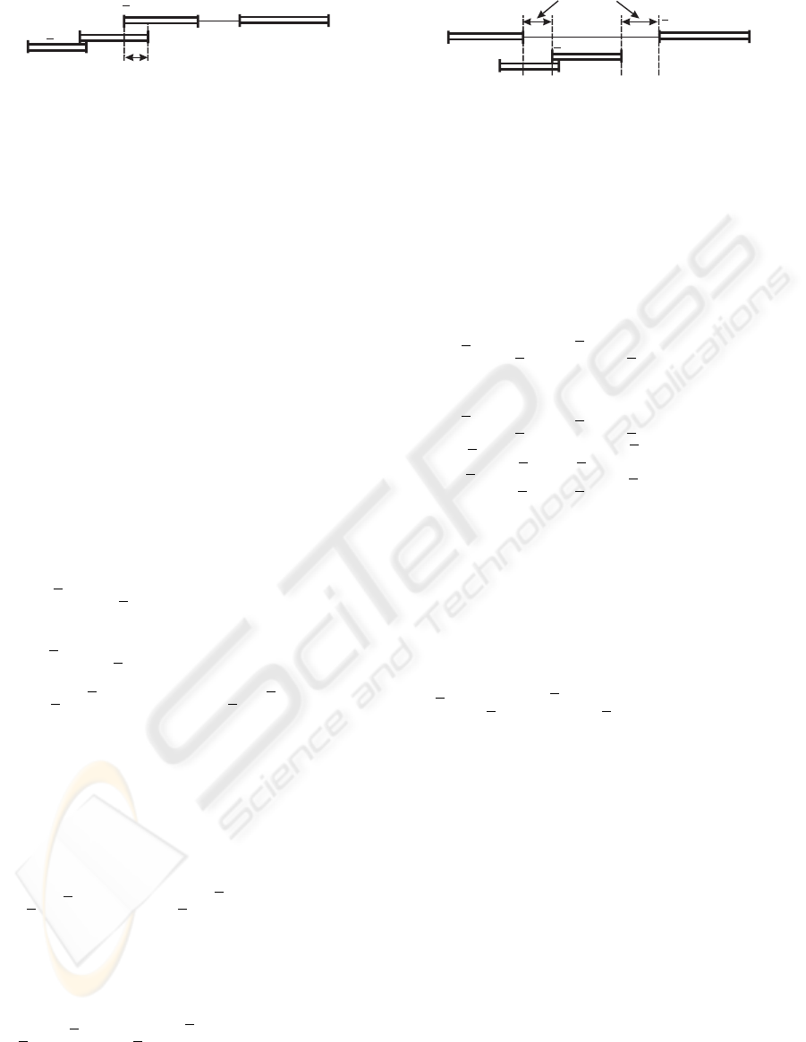
Figure 4: Only if two intervals that contain the minimum
and the maximum projection interval of one of the trian-
gles (e.g., A
min
and A
max
) each are non-intersecting it can
be derived, that the triangles are also non-intersecting.
3 illustrates some of the cases that can occur.
Which case applies depends on the distance of the co-
ordinate intervals and the relative distance to the test
axis. The closer the point intervals are located and the
farther a point is from the test axis the more probable
it is that the projections of the point intervals intersect.
If the images of the point intervals are separated,
it can be derived which point contributes to the maxi-
mum and the minimum interval (3(a)). If neighboring
images intersect this is no longer possible (3(b)). Still,
in both of these cases a line segment which is defini-
tively occupied by the image can easily be identified.
This will be used to identify definitive intersections
with another triangle image. 3(c) shows a configura-
tion were all three images of the point intervals inter-
sect. No line segment is occupied by the image for
sure.
But in any case the greatest point projection can
vary only between the greatest maximum projection
and the greatest minimal projection. Let these be de-
noted by a
max
and a
max
. The smallest point projection
is located between the smallest minimum projection
and the smallest maximum projection. Let these be
denoted a
min
and a
min
respectively. Let the minimum
(and maximum) interval of a triangle A be denoted by
A
min
:= [a
min
, a
min
] (and A
max
:= [a
max
, a
max
])
Thus the images of the triangles become ’blurred’.
They now become intervals of intervals (compare 3).
Thus, it is now longer obvious, which configurations
of two triangle projections need to be interpreted as
intersecting and which implicate that the triangles are
non-intersecting.
The latter is the simpler of the two cases and thus
is tackled first. Consider the two intervals that con-
tain the extreme boundaries of each projected triangle
A = [a
min
, a
max
] and B = [b
min
, b
max
]). Only if these
two intervals are non-intersecting it can be derived,
that the triangles are also non-intersecting, since in
all remaining cases the mathematically correct pro-
jections might intersect (see 4).
This accounts to the following criterion:
(b
min
> a
max
) ∨
a
min
> b
max
⇒ separation (6)
Checking for intersections is more complicated.
Especially configurations were triangle images do not
occupy a line segment for sure (see 3(c)) are causing
b
min
a
max
a
max
_
b
max
guaranteeintersection
_
Figure 5: If x ∈ A
max
, y ∈ B
max
implies that x < y, then
the projections will intersect for sure only if x ∈ A
max
, y ∈
B
min
⇒ y < x.
problems. If this applies to both triangles it is im-
possible to identify cases were the images intersect
for sure. To cover all remaining configurations mul-
tiple cases have to be discriminated. Consider 5. If
x ∈ A
max
, y ∈ B
max
implies that x < y, then the pro-
jections will only intersect for sure, if x ∈ A
max
, y ∈
B
min
⇒ y < x. This accounts to the following crite-
rion:
case(a
max
< b
max
) :
b
min
< a
max
⇔ intersection
(7)
Very analogously further criteria can be identified:
case
b
max
< a
max
: (a
min
< b
max
) ⇔ intersection
case(a
min
< b
min
) :
a
max
< b
min
⇔ intersection
case
b
min
< a
min
: (b
max
< a
min
) ⇔ intersection
(8)
If the images are not definitively separate, but none of
the above cases applies we know that the maximum
intervals A
max
and B
max
intersect and that the mini-
mum intervals A
min
and B
min
intersect. In this case
we have to ensure, that the surely occupied spaces do
overlap, before an intersection can be derived.
All remaining cases :
(a
min
< b
max
) ∧
b
min
< a
max
⇔ intersection
(9)
If the images are neither intersecting nor separated
for sure, the result of the axis test is marked as pos-
sibly incorrect. We experimented with various ap-
proaches to provide an educated guess on the exact
outcome, but none yielded satisfying results. Thus
the simplest solution was chosen and all possibly in-
correct results are assumed to be intersections. This
is the weaker assumption and will be corrected by
any definitive separating axis found, since in this case
the triangles do not intersect for sure. If no separat-
ing axis was found, but any of the axes tests returned
a possibly incorrect intersection the overall result of
the triangle intersection test is ’possibly incorrect in-
tersection’. This enables the user to decide on how
to proceed. Here an exact software intersection test
could be applied for example. This way the number
of possibly incorrect results has a major impact on the
overall performance and must be decreased as much
as possible, without impairing resource consumption.
GRAPP 2009 - International Conference on Computer Graphics Theory and Applications
358
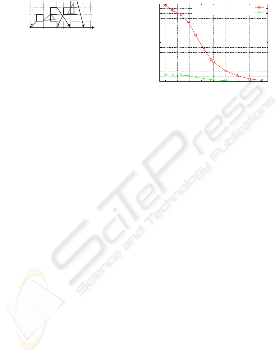
Figure 6: Two triangles that are relatively far from each
other considering their sizes. Since they are very small
considering the discretization grid induced by the data-type
used for the images, the latter still intersect.
2.5 Decreasing the Number of Possibly
Wrong Results
The target architecture is a Xilinx Virtex II (XC
2V6000, speed grade -4) on an Alpha Data ADM-
XRC-II board with 256 MB DDR-RAM at 100MHz
clock frequency. The FPGA features 144 18-bit mul-
tipliers and 6 million gate equivalents. Cascading the
multipliers to yield bit widths up to 32-bit is pro-
hibitively expensive since it quadruples the number of
multipliers used. For benchmarking we integrated the
previously introduced design into the hierarchical col-
lision detection architecture presented in (Raabe et al.,
2006). We used two identical objects (a car headlight)
with 5947 triangles. They are placed in different dis-
tances from each other and with different rotations.
For each constellation, the time to detect all intersect-
ing triangles is determined. Due to the 18-bit restric-
tion this yields relatively poor results. In this simu-
lation only 16.8% of the queries are exact outcomes.
This is unacceptable since it implies that the host PC
needs to retest almost all triangle pairs. Therefore a
very efficient and effective optimization is proposed
in the following.
We already normalized the triangles in 2.2 to en-
able fixed-point implementation. Still there can be
very small triangles compared to the largest one. In
the presented framework triangles of sizes close to
the fixed-point resolution cause numerical problems,
even if the triangles are not closely located with re-
spect to their sizes (6). To avoid such configurations
the triangle pair can be re-normalize individually on-
chip prior to the actual intersection test. This de-
creases the fixed-point resolution relatively to the dis-
tance of the triangles.
One way to accomplish this is to shift the barycen-
ter of the triangles into the origin and stretch them to
the outer limits of the fixed-point domain. The lat-
ter can be done individually for the coordinate axes to
maximize the effect without impairing the outcome
of the collision query. To enable efficient implemen-
tation, this is approximated by shifting an arbitrary
point of the triangles into the origin and shifting the
rest consistently. Afterward bit-wise or is applied to
the absolute values of the coordinates of all 6 triangle
0
10
20
30
40
50
60
70
80
90
100
110
120
130
140
150
160
0.6 0.7 0.8 0.9 1 1.1 1.2 1.3 1.4
Runtime / ms
Object Distance
Software
FPGA with LTA and two pipelines
Figure 7: The EFSAT implementation is integrated into a
hierarchical collision detection accelerator hardware. The
overall design still yields a speed-up of an order of mag-
nitude compared to a state-of-the-art software implemen-
tation. The latter does not provide categorization of exact
results or any guarantees on correctness.
points for their x-,y-, and z-coordinates. The number
of leading zeros now denotes the number of bits in-
significant for the further calculation. All coordinates
are shifted accordingly. Now only the matrix multi-
plication that transforms
e
B into A’s reference frame
is implemented in 32-bit precision. The projection it-
self is done in 18-bit. Using this scheme 99.1% of the
results are exact. This will suffice for the vast major-
ity of applications and enables retesting in all others
without impairing the overall performance.
3 RESULTS
3.1 Comparing EFSAT to M
¨
oller and
SAT
The overall design still yields a speed-up of an order
of magnitude compared to a state-of-the-art software
implementation (Zachmann, 1998) of a hierarchical
collision detection running on a system with an iden-
tical memory interface (see 7). The latter does nei-
ther provide categorization of exact results, nor does
it provide any guarantees on correctness.
In terms of precision the presented approach can
even compete with double precision floating-point
implementations of the M
¨
oller and the SAT approach.
1 shows a comparison of the three approaches. As
can be seen there exist cases where SAT and M
¨
oller
disagree. Even in some of these cases the approach
presented in this paper provides a definitive answer to
the query.
EFSAT - An Exact and Efficient Triangle Intersection Test Hardware
359

Table 1: Comparing EFSAT with double precision floating-
point implementations of M
¨
oller and SAT.
EFSAT M
¨
oller SAT %
Sep. Sep. Sep. 70.93
Sep. Sep. Int. 0
Sep. Int. Sep. 0.02
Sep. Int. Int. 0
Int. (p.i.) Sep. Sep. 0.13
Int. (p.i.) Sep. Int. 0
Int. (p.i.) Int. Sep. 0.04
Int. (p.i.) Int. Int. 0.77
Int. Sep. Sep. 0
Int. Sep. Int. 0
Int. Int. Sep. 0
Int. Int. Int. 28.13
3.2 Resource Consumption
Implemented in VHDL and synthesized, placed and
routed with Xilinx ISE 8.1 the design’s resource con-
sumption is extraordinarily modest. It uses a total of
only 72 18-bit multipliers and 48% of available gates.
4 CONCLUSIONS
This paper presents the EFSAT approach, a fixed-
point hardware implementation of the SAT algorithm,
which categorizes its results into exact and possibly
incorrect. An additional optimization improves the
resolution of the algorithm, so that it can compete
with double precision floating-point implementations
of M
¨
oller’s algorithm and the standard SAT. The ap-
proach is extremely resource efficient. It was imple-
mented and tested in VHDL. It utilizes a total of only
72 18-bit multipliers and 48% of available gate equiv-
alents. This enables fitting it into a Xilinx Virtex-
II XC 2V6000 together with a hierarchy traversal
module. The overall design is ten times faster than a
state-of-the-art software implementation running on a
system with identical memory bandwidth, which does
not provide any guarantees on correctness or catego-
rization of the results. This renders the EFSAT imple-
mentation resource efficient, fast, and exact.
5 FUTURE WORK
Due to definition 1 every test axis is orthogonal to
at least two triangle edges. Thus the projections of
the two triangle points defining this axis are identical.
This is exploited in the original SAT-test to reduce the
number of projections and comparisons. It remains
unclear if this holds for the given algorithm as well
and thus will be evaluated.
In all our experiments EFSAT returns correct an-
swers to collision queries concerning colinear trian-
gles, although only 11 axes are tested instead of the
17 necessary for this in the original SAT. It remains
an open problem if this can be generalized.
Currently we are working on a software imple-
mentation of the SAT algorithm using interval arith-
metic and floating-point numbers to provide a fast and
precise arithmetic filter.
REFERENCES
Gottschalk, S. (1996). Separating Axis Theorem. Technical
Report TR-96-024.
Held, M. (1996). ERIT – A collection of efficient and re-
liable intersection tests. Technical Report, University
at Stony Brook.
Karamcheti, V., Li, C., Pechtchanski, I., and Yap, C. (1999).
A core library for robust numeric and geometric com-
putation. In SCG ’99, New York, USA. ACM.
Mehlhorn, K. and Schirra, S. (2001). Exact computation
with leda real - theory and geometric applications. In
Symbolic Algebraic Methods and Verification Meth-
ods, pages 163–172.
M
¨
oller, T. (1997). A Fast Triangle-Triangle Intersection
Test. journal of graphics tools, 2(2):25–30.
Plante, E., Cani, M.-P., and Poulin, P. (2001). A layered
wisp model for simulating interactions inside long
hair. In Computer Animation and Simulation 2001,
Computer Science.
Raabe, A., Hochgurtel, S., Zachmann, G., and Anlauf, J. K.
(2006). Space-Efficient FPGAAccelerated Collision
Detection for Virtual Prototyping. In Design Automa-
tion and Test (DATE), pages 206211, Munich, Ger-
many.
Raabe, A., Nett, A., and Niers, A. (2008). A Refinement
Case-Study of a Dynamically Reconfigurable Inter-
section Test Hardware. In ReCoSoc08.
Robbins, S. and Whitesides, S. (2003). On the reliability of
triangle intersection in 3d. In ICCSA (3), pages 923–
930.
Shewchuk, J. R. (1997). Adaptive precision floating-point
arithmetic and fast robust geometric predicates. Dis-
crete & Computational Geometry, 18(3):305–368.
Weller, R., Klein, J., and Zachmann, G. (2006). A model for
the expected running time of collision detection using
aabb trees. In Eurographics Symposium on Virtual En-
vironments (EGVE), Lisbon, Portugal.
Woulfe, M., Dingliana, J., and Manzke, M. (2007). Hard-
ware accelerated broad phase collision detection. In
SIGGRAPH 2007, New York, USA. ACM SIG-
GRAPH.
Zachmann, G. (1998). Rapid Collision Detection by
Dynamically Aligned DOP-Trees. Proc. of IEEE,
VRAIS’98 Atlanta.
GRAPP 2009 - International Conference on Computer Graphics Theory and Applications
360
