
A VIRTUAL REALITY SIMULATOR FOR ACTIVE STEREO VISION
SYSTEMS
Manuela Chessa, Fabio Solari and Silvio P. Sabatini
Department of Biophysical and Electronic Engineering, University of Genoa - Via all’Opera Pia 11/A - 16145 Genova, Italy
Keywords:
Binocular vision, Active fixation, Virtual reality, Ground truth data.
Abstract:
The virtual reality is a powerful tool to simulate the behavior of the physical systems. The visual system
of a robot and its interplay with the 3D environment can be modeled and simulated through the geometrical
relationships between the virtual stereo cameras and the virtual 3D world. The novelty of our approach is
related to the use of the virtual reality as a tool to simulate the behavior of active vision systems. In the
standard way, the virtual reality is used for the perceptual rendering of the visual information exploitable by
a human user. In the proposed approach, a virtual world is rendered to simulate the actual projections on the
cameras of a robotic system, thus the mechanisms of the active vision are quantitatively validated by using the
available ground truth data.
1 INTRODUCTION
In 3D computer vision (Trucco and Verri, 1998) and
in particular for the stereoscopic vision, it is impor-
tant to assess quantitatively the progress in the field,
but too often the researchers reported only qualitative
results on the performance of their algorithms due to
the lack of calibrated stereo image databases. To over-
come this problem, in the literature we can find works
that provide test beds for a quantitative evaluation of
the stereo algorithms. Towards this end, the calibrated
data sets (Scharstein and Pal, 2007) have to provide
both the stereo images and the ground truth disparity
map. The left and right intensity patterns observed by
the two cameras result related by the binocular dispar-
ity map that varies as a function of the spatial position
and of the geometry of the vision system. A different
approach is to generate stereo image pairs by using a
database of range images collected with a laser range-
finder, e.g. (Huang et al., 2000). In this case, we have
to compute the stereo projections to obtain the stereo
images. In general, the major drawback of the cali-
brated data sets is the lack of interactivity: it is not
possible to change the scene and the camera point of
view. The camera position can be slightly modified
by using the laser range-finder data, but this move-
ment produces undesired occlusions.
The interaction between the visual scene and the
vision system is the main characteristic of an active
vision system, e.g. a robot system. The paradigm of
the active vision was introduced in order to overcome
the efficiency and stability caveats of conventional
computer vision systems (Aloimonos et al., 1988). A
common principle of this paradigm is the behavior-
dependent processing of visual data by shifting the
fixation point on different targets (active foveation)
for attentive visual scrutiny. Selective attention and
foveation imply the ability to control the mechani-
cal and optical degrees of freedom during image ac-
quisition process (Dankers and Zelinsky, 2004). In
such systems the camera movements bring the object
of interest in the center of the image pair (by per-
forming camera rotations), and these vergence move-
ments generate both horizontal and vertical dispar-
ity (Theimer and Mallot, 1994; Read and Cumming,
2006). These effects can be observed in Fig 1 that
shows the real-world images gathered by a binocular
robotic head, that is fixating a specific point in the
scene through vergence movements.
The aim of this work is to provide a virtual reality
tool that implements the requirements imposed by an
active vision system and allows the changing of the
geometry of the virtual stereo cameras as a function
of the visual input to the active system. Such a tool,
exploiting the ground truth available from the virtual
world and the related projected stereo images, pro-
444
Chessa M., Solari F. and P. Sabatini S. (2009).
A VIRTUAL REALITY SIMULATOR FOR ACTIVE STEREO VISION SYSTEMS.
In Proceedings of the Fourth International Conference on Computer Vision Theory and Applications, pages 444-449
DOI: 10.5220/0001783504440449
Copyright
c
SciTePress
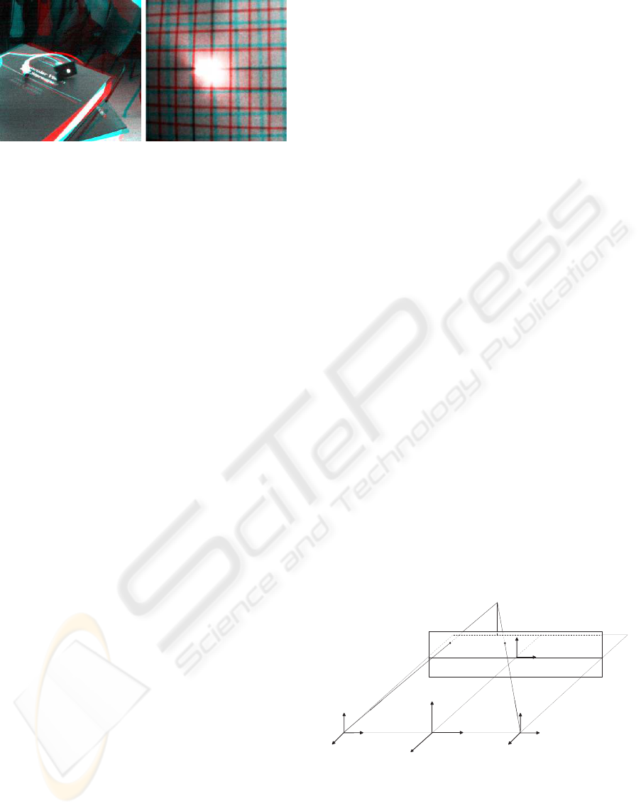
(a) (b)
Figure 1: Binocular snapshots obtained by a real-world ac-
tive vision system. The two cameras are fixating different
objects in the scene (a) the LED on the book and (b) the
center of a fronto-parallel grid drawn on a sheet of paper.
The anaglyphs are obtained with the left image on the red
channel and the right image on the green and blue channels.
The interocular distance is 8 cm and the camera resolution
is the standard VGA 640× 480 pixels with a focal length of
6 mm. The distance between the cameras and the objects
is between 50 cm and 90 cm. It is worth noting that both
horizontal and vertical disparities are present.
vides a way to validate the behavior of an activevision
system in a controlled and realistic scenario. The pa-
per is organized as follows: in Section 2 we describe
the state of art of the robotic simulators. In Section 3
we briefly introduce the two main methods of setting
up virtual cameras and rendering stereo image pairs.
In Section 4 we describe the proposed method, the
implementation of the active vision behavior and the
technique for the ground truth generation. Finally in
Section 5 we present the results.
2 RELATED WORKS
Recent works on robot simulators address the prob-
lem of endowing the systems with visual capabilities
(e.g.
www.cyberbotics.com
), even if the stereo vi-
sion is often intended for future developments, e.g.
(Jørgensen and Petersen, 2008; Awaad et al., 2008).
Other robot simulators in the literature have a binocu-
lar vision system. In (Okada et al., 2002) the authors
described a simulator of an humanoid robot with 18
degree of freedom (DOF), but only 2 DOF are for the
binocular head, thus producing a parallel axis stereo
vision. Similarly in (Ulusoy et al., 2004) a virtual
robot with an active stereo vision system is presented,
but the authors state that they work on stereo image
pairs where parallel cameras are used. A virtual hu-
man with an active stereo vision system is described
in (Rabie and Terzopoulos, 2000), where the two eyes
can fixate a target in a scene by computing the stereo
disparities between the left and the right foveal im-
ages.
Our aim is to simulate an active vision system
rather then the whole aspects of a robot acting in an
environment (e.g. navigation and mechanical move-
ments of the robot itself). In particular, we aim to
precisely simulate the vergence movements of the two
cameras in order to provide the stereo views and the
related ground truth data (horizontal and vertical dis-
parities and binocular optic flow). Thus, our virtual
system can be used for two different purposes: (a)
to produce visual behaviors, in a closed loop with a
control strategy of the vergence movements guided
by a vision-based information; (b) to obtain stereo se-
quences with related ground truth, to quantitatively
assess the performances of computer vision algo-
rithms.
3 THE COMPUTATION OF THE
STEREO IMAGE PAIR
In the literature the main methods to render stereo im-
age pairs are (Bourke and Morse, 2007): (1) the off-
axis technique, usually used to create a perception of
depth for a human observer and (2) the toe-in tech-
nique that can simulate the actual intensity patterns
impinging on the cameras of a robotic head.
In the off-axis technique, the stereo images are
generated by projecting the objects in the scene onto
the display plane for each camera; such projection
plane has the same position and orientation for both
camera projections. The model of the virtual setup is
shown in Fig 2: F represents the location of the vir-
tual point perceived when looking at the stereo pair
composed by F
L
and F
R
. This is the correct way to
X
L
Y
L
Z
L
X
R
Y
R
Z
R
X
Y
Z
F
O
L
O
R
O
x
y
o
F
L
F
R
Figure 2: Geometrical sketch of the off-axis technique.
The left and right camera frames: (X
L
,Y
L
,Z
L
) and
(X
R
,Y
R
,Z
R
). The image plane (x,o,y) and the focal length
Oo. The image points F
L
and F
R
are the stereo projection
of the virtual point F. The baseline b is denoted by O
L
O
R
.
create stereo pairs that are displayed on stereoscopic
devices for human observers. This technique intro-
A VIRTUAL REALITY SIMULATOR FOR ACTIVE STEREO VISION SYSTEMS
445
duces no vertical disparity, thus it does not cause dis-
comfort for the users.
Since our aim is to simulate the actual images ac-
quired by the cameras of a verging pan-tilt robotic
head, the correct way to create the stereo pairs is the
toe-in method: each camera is pointed at a single fo-
cal point (the fixation point) through a proper rotation.
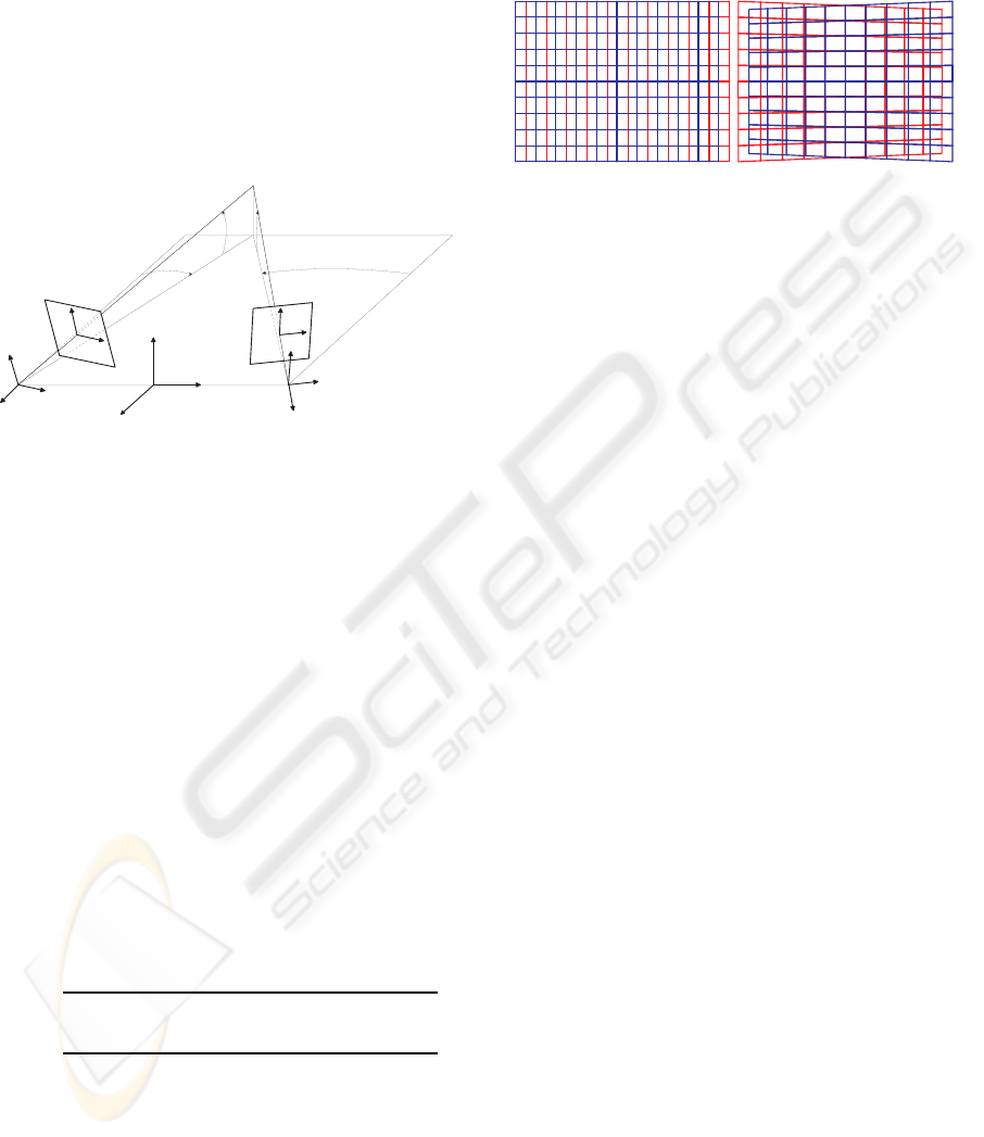
The geometrical sketch of the optical setup of an ac-
tive stereo system and of the related toe-in technique
is shown in Fig 3. The relation between the 3D world
a
L
a
R
x
L
x
R
y
L
X
L
Y
L
Z
L
X
R
Y
R
Z
R
X
Y
Z
y
R
b
L
b
R
F
O
L
O
R
O
o
L
o
R
Figure 3: Geometrical sketch of the toe-in technique.
The left and right camera frames: (X
L
,Y
L
,Z
L
) and
(X
R
,Y
R
,Z
R
). The left and right image planes: (x
L
,o
L
,y
L
)
and (x
R
,o
R
,y
R
). The left and right focal lengths: O
L
o
L
=
O
R
o
R
, named f
0
. The camera optical axes O
L
F and O
R
F
are adjusted to the fixation point F. The baseline b is de-
noted by O
L
O
R
, the slant angles by α
L
and α
R
, and the tilt
angles by β
L
and β
R
.
coordinates X = (X,Y,Z) and the homogeneous im-
age coordinates x
L
= (x
L
,y
L
,1) and x
R
= (x
R
,y
R
,1)
for the toe-in technique is described by a general per-
spective projection model. A generic point X in the
world coordinates is mapped onto image plane points
x
L
and x
R
on the left and right cameras, respectively.
It is worth noting that the fixation point F in Fig 3 is
projected onto the origins of the left and right image
planes, since the vergence movement makes the op-
tical axes of the two cameras to intersect in F. For
identical left and right focal lengths f
0
, the left image
coordinates are (Volpel and Theimer, 1995):
x
L
= f
0
X
+
cosα
L
+ Zsinα
L
X
+
sinα
L
cosβ
L
− Y sinβ
L
− Z cosα
L
cosβ
L
y
L
= f
0
X
+
sinα
L
sinβ
L
+Y cosβ
L
− Z cosα
L
sinβ
L
X
+
sinα
L
cosβ
L
− Y sinβ
L
− Z cosα
L
cosβ
L
where X
+
= X + b/2. Similarly, the right image co-
ordinates are obtained by substituting in the previous
equations α
R
, β
R
and X
−
= X − b/2. We can define
the horizontal disparity d
x
= x
R
− x
L
and the vertical
disparity d
y
= y
R
− y
L
, that establish the relationships
between a world point X and its associated disparity
vector d = (d
x
,d
y
). The disparity patterns produced
by the off-axis and toe-in techniques are shown in
Fig 4a and Fig 4b, respectively.
(a) (b)
Figure 4: The projections of a fronto-parallel square onto
the image planes, drawn in red for the left image and blue
for the right. The texture applied to the square is a reg-
ular grid. (a) The projection obtained with the off-axis
technique: only horizontal disparity is introduced. (b) The
projection obtained with the toe-in technique: both verti-
cal and horizontal disparities are introduced. The projected
patterns resemble the ones obtained in real-world situations
(see Fig. 1b).
4 IMPLEMENTATION
The virtual reality tool we propose in this paper is
based on a C++ / OpenGL architecture and on the
Coin3D graphic toolkit (
www.coin3D.org
). Coin3D
is built on OpenGL and uses scene graph data struc-
tures to render 3D graphics in real time. Both
OpenGL and Coin3D code co-exist in our application.
4.1 Stereo Implementation
To implement the stereo geometry described in the
Section 3 we modified the
SoCamera
node in Coin3D
distribution. The
SoCamera
class is the abstract base
class for camera definition nodes and it can be used
to obtain a stereoscopic visualization of the scene.
The stereoscopic technique usually implemented is
the off-axis technique, described in Section 3. Our
aim is to add the toe-in technique, to generate stereo
pairs like in a pan-tilt robotic head.
Accordingly, we introduced the possibility of
pointing the left and the right views at a single fo-
cal point, keeping fixed and symmetric the two view
volumes and rotating them. To obtain the left and
the right views both fixating a point F, a symmetric
view volume is created, centered in the position O =
(X,Y,Z) (see Fig. 3). The skewed frustum (necessary
to obtain the off-axis stereo technique) is no longer
necessary. The view volume is then translated to the
positions O
L
= (X
L
,Y
L
,Z
L
) and O
R
= (X
R
,Y
R
,Z
R
) in
order to obtain the stereo separation b. The translation
for the left and the right view volume can be obtained
VISAPP 2009 - International Conference on Computer Vision Theory and Applications
446

by applying the following translation matrix:
T
L/R
=
1 0 0 ±
b
2
0 1 0 0
0 0 1 0
0 0 0 1
(1)
Then the azimuthal rotation (α
L
and α
R
) and the
elevation (β
L
and β
R
) are obtained with the following
rotation matrices:
R
L/R
α
=
cosα
L/R
0 sinα
L/R
0
0 1 0 0
− sinα
L/R
0 cosα
L/R
0
0 0 0 1
(2)
R
L/R
β
=
1 0 0 0
0 cosβ
L/R
− sinβ
L/R
0
0 sinβ
L/R
cosβ
L/R
0
0 0 0 1
(3)
The complete roto-translation of the view-
volumes is:
O
L/R
1
= R
L/R
β
R
L/R
α
T
L/R
O
1
(4)
Thus, the projection direction is set to the target
point F, then the left and the right views project onto
two different planes, as it can be seen in Fig 3.
In this way, it is possible to insert a camera in the
scene (e.g. a perspective camera), to obtain a stereo-
scopic representation with convergent axis and to de-
cide the location of the fixation point. This emulates
the behavior of a couple of verging pan-tilt cameras.
4.2 Active Vision Implementation
The described tool is active in the sense that the fix-
ation point F of the stereo cameras varies to explore
the scene. We can distinguish two possible scenarios:
(1) to use the system to obtain sequences where the
fixation points are chosen on the surfaces of the ob-
jects in the scene; (2) to use the system in cooperation
with an algorithm that implements a vergence/version
strategy. In the first case, it is not possible to fixate
beside or in front of the objects. In the second case,
the vergence/version algorithm gives us an estimate
of the fixation point, the system adapts itself looking
at this point and the snapshots of the scene are then
used as a new input for selecting a new target point.
In this work, we focused on the first issue, and
we want the system to fixate points laying on the ob-
jects’ surfaces. To this end, it is necessary to de-
rive the 3D coordinates of all the visible surfaces.
This information can be obtained from the z-buffer
with the
glReadPixels
function, from which we ob-
tain the 3D window coordinates, that are mapped
into the object coordinates, through the function
gluUnproject
, by using the transformations defined
by the
ModelView
matrix, the
Projection
matrix
and the
Viewport
(Hearn and Baker, 1997; Wrigh
et al., 2007).
4.3 Ground Truth Data Generation
To compute the ground truth data for the horizon-
tal and vertical disparities of the stereo image pairs,
given the projection of a 3D virtual point in one image
plane, we have to look for the correspondent projec-
tion in the other image plane. Formally, the two cam-
era reference frames are related by a rigid body trans-
formation described by the rotation matrix R and the
translation T . The left and right projections are re-
lated by the same transformation in the following way
(Ma et al., 2004):
λ
R
x
R
= R λ
L
x
L
+ T (5)
where x
L
and x
R
are the homogeneous coordinates in
the two image planes, and λ
L
and λ
R
are the depth
values.
To apply the relationship described by Eq. 5 we
first read the z-buffer (w) of the two stereo views
through the
glReadPixels
function, then we obtain
the depth values with respect to the reference frames
of the two cameras in the following way:
λ
L/R
=
f n
w
L/R
( f − n) − f
(6)
where f and n represent the values of the far and the
near planes of the virtual camera. Starting from the
image coordinate x
L
of the left image and the depth
values λ
L/R
obtained by Eq. 6, we obtain the image
coordinate x
R
of the right view by combining the roto-
translation described in Eq. 4 and Eq. 5 in the follow-
ing way:
λ
R
x
R
= R
R
T
R
(T
L
)
−1
(R
L
)
−1
λ
L
x
L
(7)
where R
L/R
= R
L/R
β
R
L/R
α
. Finally the horizontal dis-
parity d
x
= x
R
− x
L
and the vertical disparity d
y
=
y
R
− y
L
are computed.
5 RESULTS
The described tool produces couples of stereo im-
ages, from a pair of stereoscopic vergent cameras in
a scene where the 3D coordinates of the objects and
their 2D projections are known and controlled. The
fixation point of the two cameras is set by using the
actual depth values referred to the cyclopic position,
A VIRTUAL REALITY SIMULATOR FOR ACTIVE STEREO VISION SYSTEMS
447
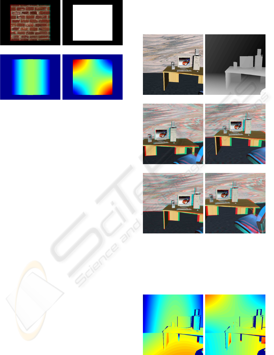
(a) (b)
(c) (d)
Figure 5: (a) Anaglyph of a stereo pair obtained from the
two virtual cameras fixating the center of a fronto-parallel
plane. (b) Depth map referred to the cyclopic position. (c-d)
Horizontal and vertical ground truth disparity maps, coded
from red (positive values of disparity) to blue (negative val-
ues). Zero disparity is coded in green.
moreover the ground truth disparities between the two
views are computed. Figure 5c-d shows the typical
horizontal and vertical disparity patterns that emerge
when two cameras are fixating the center of a fronto-
parallel plane. It is worth noting that these patterns
are similar both to the geometrically obtained pro-
jections (see Fig. 4b) and to the disparities present
in the images acquired by a real-world active vision
system (see Fig. 1b). Since our aim is to obtain a sim-
ulator that behaves like a robotic binocular head in a
real-world environment, it is necessary to create quite
complex scenarios. In particular, it is necessary to
have different objects at different depths, with “realis-
tic” textures, in order to create benchmark sequences
of appropriate complexity. In Fig 6 we present some
examples for a virtual environmentrepresenting a typ-
ical indoor situation (an office). The simulator aims to
mimic the behavior of an active system with human-
like features acting in the peripersonal space, thus the
interocular distance between the two cameras is set
to 6.5 cm and the distance between the cameras and
the objects ranges between 80 and 90 cm. The dif-
ferent fixation points have been chosen randomly, by
using the depth map of Fig 6b, where dark gray val-
ues correspond to far objects, while light gray values
correspond to near objects. The aim of this test was
to create a set of images gathered by different fixa-
tion points, thus simulating an active exploration of
the scene. The results of this exploration are shown
in Fig 6c-f. It is worth noting that in the proximity
of the fixation point the disparity between the left and
the right projections is zero, while getting far from the
fixation point both horizontal and vertical disparities
emerge (Theimer and Mallot, 1994; Read and Cum-
ming, 2006), as it can be seen in the ground truth data
of Fig 7.
(a) (b)
(c) (d)
(e) (f)
Figure 6: Snapshots obtained by our simulator of an active
vision system. (a) The virtual scenario used for testing the
developed tool. (b) Depth map referred to the initial posi-
tion of the cameras. The stereoscopic cameras are exploring
the scene by fixating different objects in the scene: (c) the
case, (d) the keyboard, (e) the left speaker and (f) the mouse.
(a) (b)
Figure 7: The horizontal and vertical ground truth disparity
maps of the stereo pair of Fig 6e. Occlusions are marked
with dark blue.
VISAPP 2009 - International Conference on Computer Vision Theory and Applications
448

6 CONCLUSIONS AND FUTURE
WORK
We have described a virtual reality tool, capable of
generating pairs of stereo images like the ones that
can be obtained by a verging pan-tilt robotic head and
the related ground truth data.
To obtain such a behavior the toe-in stereo-
scopic technique should be preferred to the off-axis
technique. By proper rototranslations of the view
volumes, we can create benchmark sequences for
vision systems with convergent axis. Moreover, by
using the precise 3D position of the objects these
vision systems can interact with the scene in a
proper way. A data set of stereo image pairs and
the related ground truth disparities are available for
the Computer Vision community at the web site
www.pspc.dibe.unige.it/Research/vr.html
.
Since the purpose of this work was not to create
a photo-realistic virtual reality tool but to obtain
sufficiently complex scenarios for benchmarking an
active vision system, we have not directly addressed
the problem of improving the photo-realistic quality
of the 3D scene, rather we focused on the definition
of a realistic model of the interactions between the
vision system and the observed scene. The creation
of even more complex and photo-realistic scenes will
be part of a future work.
Furthermore, we will integrate vergence/version
strategies in the system in order to have a really ac-
tive tool that interacts with the virtual environments.
It would also be interesting to modify the standard
pan-tilt behavior by including more biologically plau-
sible constraints on the camera movements (Schreiber
et al., 2001; Van Rijn and Van den Berg, 1993).
ACKNOWLEDGEMENTS
We wish to thank Luca Spallarossa for the helpful
comments.
REFERENCES
Aloimonos, Y., Weiss, I., and Bandyopadhyay, A. (1988).
Active vision. Int. J. of Computer Vision, 1:333–356.
Awaad, I., Hartanto, R., Le´on, B., and Pl¨oger, P. (2008). A
software system for robotic learning by experimenta-
tion. In Workshop on robot simulators (IROS08).
Bourke, P. and Morse, P. (2007). Stereoscopy: Theory and
practice. Workshop at 13th International Conference
on Virtual Systems and Multimedia.
Dankers, A. and Zelinsky, A. (2004). Cedar: A real-world
vision system: Mechanism, control and visual pro-
cessing. Machine Vision and Appl., 16(1):47–58.
Hearn, D. and Baker, M. P. (1997). Computer Graphics, C
Version. 2nd edition. Prentice Hall.
Huang, J., Lee, A. B., and Mumford, D. (2000). Statistics
of range images. In Proc. of the IEEE Conference on
Computer Vision and Pattern Recognition.
Jørgensen, J. and Petersen, H. (2008). Usage of simula-
tions to plan stable grasping of unknown objects with
a 3-fingered schunk hand. In Workshop on robot sim-
ulators (IROS08).
Ma, Y., Soatto, S., and Kosecka, J.and Sastry, S. (2004).
An Invitation to 3D Vision. From Images to Geometric
Models. Springer-Verlag.
Okada, K., Kino, Y., and Kanehiro, F. (2002). Rapid devel-
opment system for humanoid vision-based behaviors
with real-virtual common interface. In IEEE/RSJ Int.
Conf. on Intelligent Robots and Systems.
Rabie, T. F. and Terzopoulos, D. (2000). Active perception
in virtual humans. In Vision Interface 2000 (VI 2000).
Read, J. and Cumming, B. (2006). Does depth perception
require vertical disparity detectors? Journal of Vision,
6(12):1323–1355.
Scharstein, D. and Pal, C. (2007). Learning conditional ran-
dom fields for stereo. In Proc. of the IEEE Conference
on Computer Vision and Pattern Recognition.
Schreiber, K. M., Crawford, J. D., Fetter, M., and Tweed,
D. B. (2001). The motor side of depth vision. Nature,
410:819–822.
Theimer, W. and Mallot, H. (1994). Phase-based binocular
vergence control and depth reconstruction using active
vision. CVGIP: Image Understanding, 60(3):343–
358.
Trucco, E. and Verri, A. (1998). Introductory Techniques
for 3-D Computer Vision. Prentice Hall.
Ulusoy, I., Halici, U., and Leblebicioglu, K. (2004). 3d
cognitive map construction by active stereo vision in
a virtual world. Lecture notes in Computer Science,
3280:400–409.
Van Rijn, L. and Van den Berg, A. (1993). Binocular eye
orientation during fixations: Listing’s law extended to
include eye vergence. Vision Research, 33:691–708.
Volpel, B. and Theimer, W. (1995). Localization uncertainty
in area-based stereo algorithms. IEEE Transactions on
Systems, Man and Cybernetics, 25(12):1628–1634.
Wrigh, R., Lipchack, B., and Haemel, N. (2007). OpenGL
superbible, Fourth Edition, Comprehensive Tutorial
and Reference. Addison-Wesley.
A VIRTUAL REALITY SIMULATOR FOR ACTIVE STEREO VISION SYSTEMS
449
