
EVALUATION OF SUN POSITION USING THE PHOTOVOLTAIC
GENERATION
An Application for Attitude Estimation in Box-Shape Satellites
Ronilson Rocha, Alexandre Jos´e Ferreira, Caio Pequeno Gouvˆeia and Talita Bueno Barbosa
School of Mines - Department of Engineering of Control and Automation
Federal University of Ouro Preto, Campus Morro do Cruzeiro, 35400-000, Ouro Preto, MG, Brazil
Keywords:
Artificial Satellites, Attitude Determination, Photovoltaic System.
Abstract:
It is necessary at least two or more independent known vectors for attitude determination of an artificial
satellite. One of these vectors can be the Earth Magnetic Field, which is used as reference in navigation for
centuries. Other reference can be the sun, which is easily distinguished of other astronomical objects in the
proximities of the Earth. While the Earth Magnetic Field can be measured by a small solid-state three-axis
magneto-resistive transducer, the own photovoltaic system of the artificial satellite can provide a evaluation of
the azimuthal position of the sun. This paper presents a way to estimate the sun position from the own satellite
power system. This information is used for attitude determination, allowing the integration of two important
subsystems of an artificial satellite.
1 INTRODUCTION
An artificial satellite is a component of a spatial sys-
tem, an ample set of elements in the space (other
satellites, spacecrafts, spatial stations, etc.) and in
the ground (tracking stations, antennas, control cen-
ters, etc.). For the realization of a spatial mission,
an artificial satellite transports several onboard equip-
ments, such as radars, antennas, telescopes, photo-
graphic cameras, equipments for scientific measures,
etc. The power supply for onboard equipments has
vital importance in an artificial satellite. Considering
characteristics such as modularity, cost, maintenance
and life, the photovoltaic generation is the more ade-
quate energy resource for spatial applications. Since
the light-generated power in photovoltaic arrays is
highly dependent of the intensity and direction of the
incident sunlight, it is considerably variable in a satel-
lite and must be conditioned and regulated by power
electronic converters to supply onboard equipments.
The onboard equipments of an artificial satellite
must be pointed to a specified aim to interact with
others elements of the spatial system. Thus, the de-
termination of the spatial position and orientation of
an artificial satellite, also known as attitude, is fun-
damental for its perfect operation. The attitude re-
lated to an inertial reference is mathematically rep-
resented by an operator that rotates a vector inside
of a coordinate system, which can be estimated us-
ing algorithms that require the observation of at least
two independent and known vectors (Shuster and Oh,
1981). Several known vectors can be used as refer-
ence for attitude determination. One of these vectors
is the Geomagnetic Field, a magnetic dipole aligned
along the Earth’s rotational axis which points toward
to magnetic north. Since the sun is easily recognized
by any object near of the Earth due to its relatively
small apparent radius with a high brightness in rela-
tion to other astronomical bodies, its azimuthal posi-
tion related to artificial satellite can be considered as
a possible reference vector for attitude determination.
This paper proposes the attitude estimation of an
artificial satellite using the own photovoltaic gener-
ation to evaluate the azimuthal position of the sun.
A mathematical algorithm estimates the satellite at-
titude using this vector, which is evaluated from
the power converter operation, and the Geomagnetic
Field, which is measured using a three-axis solid-state
magnetometer. Thus, two important subsystems of an
artificial satellite can be integrated, providing various
benefits always welcome in spatial applications, such
as economy, redundancy, autonomy, etc.
177
Rocha R., Gouvêia C., Ferreira A. and Barbosa T. (2009).
EVALUATION OF SUN POSITION USING THE PHOTOVOLTAIC GENERATION - An Application for Attitude Estimation in Box-Shape Satellites.
In Proceedings of the 6th International Conference on Informatics in Control, Automation and Robotics - Robotics and Automation, pages 177-182
DOI: 10.5220/0002192601770182
Copyright
c
SciTePress
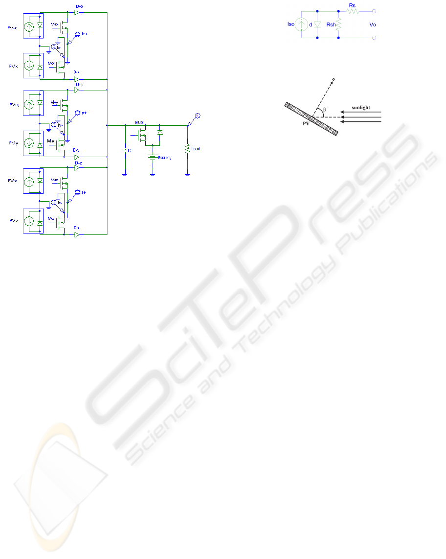
Figure 1: Sequential Shunt Regulator.
2 POWER REGULATION
An artificial satellite generally uses a regulated volt-
age bus and some form of direct energy transfer for
power conditioning of the photovoltaic energy (Shum
and Ashley, 1996). Due to a low and relatively con-
stant heat dissipation, the Sequential Shunt Regulator
(SSR) is widely used in satellite applications (Gar-
rig´os et al., 2006). This power electronic converter
is shown in Fig. 1, where is considered a segmented
photovoltaic array in six modules. Each photovoltaic
module can be admitted as a current source, which
contributions are summed by an OR connection of
very fast diodes. The photovoltaic current I can ei-
ther flow to the bus when the MOSFET switch is off,
supplying loads and batteries, or be deviated, short-
circuiting the photovoltaic module when the MOS-
FET switch is on. Since the current in the bus is
pulsed, a large capacitor filter is required to smooth
current pulses and to reduce the voltage ripple.
Since the variations in the capacitor charge re-
flect the energy exchanges between photovoltaic ar-
rays and electrical loads, the bus voltage must be
controlled to assure the power balance, restricting
the voltage variations to operational limits of the
onboard equipments. The voltage controller modu-
lates the duty cycle of a PWM signal, which simul-
taneously drives all six MOSFET’s switches of the
SSR. The battery operates in stand-by, assuming the
Figure 2: Equivalent electrical circuit of a photovoltaic cell.
Figure 3: Definition of the sunlight incidence angle β.
load when the bus voltage decreases and the series
diode becomes directly polarized, which occurs dur-
ing eclipses, faults and eventual current peeks. A
MOSFET switch can connect the battery to the power
bus for its recharge when the satellite is illuminated
again.
3 SUN POSITION ACQUISITION
Usually, the azimuthal position of the sun is evalu-
ated using a sensor based in photovoltaic cells, cam-
eras or CCD sensors (Winetraub et al., 2005; Chen
et al., 2006). However, an interesting possibility for
artificial satellites is the use of its own photovoltaic
system for evaluation of the azimuthal position of the
sun (Sityar, 1992; Santoni and Bolotti, 2000; Visc-
ito and Cerise, 2007), since the light-generated power
is highly dependent of the intensity and direction of
the incident sunlight. A photovoltaic module consists
in series-parallel arrays of several photovoltaic cells,
which equivalent electrical circuit is shown in Fig. 2.
The series resistance R
s
depends on the p-n junction
depth, impurities and the contact resistance, while the
shunt resistance R
sh
is inversely related with leakage
current to the ground. The light-generated electrical
current I
sc
depends on the efficiency of photovoltaic
conversion and the incident solar radiation over the
photovoltaic cell. This current can be approximated
by the mathematical cosine model (Patel, 1999)
I
sc
= I
sc
|
β=0
o
cosβ. (1)
where the incidence angle β is defined in the Fig.
3. Since the electrical output in the real photovoltaic
cells deviates significantly from the proposed cosine
model for β > 50
o
, this approach can lead to inac-
curacies in the determination of the sun positioning
(Winetraub et al., 2005; Sityar, 1992; Patel, 1999).
For a better accuracy, it is recommended the use of
ICINCO 2009 - 6th International Conference on Informatics in Control, Automation and Robotics
178

Figure 4: Incidence of the sunlight in a box shaped satellite.
other power-angle curves of the photovoltaic cell,
such as the Kelly cosine (Patel, 1999). Neglect-
ing the diode and shunt-leakage currents, which are
very small in real cells, the current I
sc
can be evalu-
ated short-circuitingthe output of a photovoltaicarray
(Sityar, 1992).
An illuminated box shape satellite with all six
sides covered by photovoltaic modules is shown in
Fig. 4. Considering a coordinate system constituted
by the normal axes to the surfaces of this box satellite,
a geometric inspection reveals that the components of
a vector that points towards to sun are the own sum-
mations of light-generated currents of opposite side
photovoltaic modules. Thus, the unitary vector
ˆ
s that
points towards to sun is given by
ˆ
s =
I
sc
+x
− I
sc
−x
I
sc
x
|
φ=0
o
,θ=0
o
i+
I
sc
+y
− I
sc
−y
I
sc
y
φ=90
o
,θ=0
o
j+
I
sc
+z
− I
sc
−z
I
sc
z
θ=90
o
k,
(2)
where I
sc
+x
, I
sc
−x
, I
sc
+y
, I
sc
−y
, I
sc
+z
, and I
sc
−z
are the
light-generated currents by the photovoltaicpanels re-
spectively located in the axes +x, −x, +y, −y, +z,
and −z.
The scheme for acquisition of azimuthal position
of the sun from the SSR operation is shown in Fig.
5. When the outputs of opposite photovoltaic mod-
ule are short-circuited by their respective shunt MOS-
FET’s of the power converter, a Hall current trans-
ducer measures the differential light-generated cur-
rent in the respective coordinate axis. This signal is
sampled in S/H circuit while the shunt MOSFET’s are
on. When the shunt MOSFET’s are off, the S/H cir-
cuit holds the differential current measurement, assur-
ing that this component of vector
ˆ
s is always availed
for acquisition.
4 SIMULATION RESULTS
The acquisition of the vector sun position is verified
from a computational simulation of the SSR using the
SimPowerSystems of the MATLAB/SIMULINK. It is
Figure 5: Scheme for acquisition of azimuthal position of
the sun from the SSR and bus voltage regulation.
considered that a box shape satellite is rotating in the
space at
˙
φ = 1.26rad/s and
˙
θ = 6.28rad/s (see Fig. 4).
The surface of this satellite is covered by six photo-
voltaic arrays that generates 6×10W
p
at an irradiance
of 1000W/m
2
. The sunlight irradiance in the space
is considered 1367W/m
2
. The duty cycle D of the
SSR is modulated by a PWM of 5kHz, and a capac-
itor of 1500µF is connected to power bus aiming to
reduce the voltage ripples. Since the bus capacitance
behaves as a big integrator, a simple proportional con-
troller, which gain is adjusted to 300, is enough for a
null error in the regulation of the bus voltage. The
voltage reference is adjusted to 15V to supply a resis-
tive load of 90Ω and a 12V battery. A hysteresis con-
troller monitors the battery charge and commands the
MOSFET switch, connecting the battery to the power
bus when its voltage level is the minimum. Aiming
to preserve the useful life of the battery, it is discon-
nected from bus voltage when the maximum charge is
reached.
The real and acquired azimuthal sun position is
shown in the Fig. 6. The error in the acquired vec-
tor is small, basically caused by the sample operation.
The attitude motion (angular frequencies of the satel-
lite) can be evaluated from the Fast Fourier Transform
(FFT) of the acquired data. Although the photovoltaic
power supply is highly variable due to satellite rota-
tion, the proposed P controller is enough to assure a
null voltage error, providingan excellent regulation of
the bus voltage for the considered load, as shown in
the Fig. 7.
EVALUATION OF SUN POSITION USING THE PHOTOVOLTAIC GENERATION - An Application for Attitude
Estimation in Box-Shape Satellites
179

−1
−0.5
0
0.5
1
−1
−0.5
0
0.5
1
−1
−0.5
0
0.5
1
s
x
sun position coordinates
s
y
s
z
−1
−0.5
0
0.5
1
−1
−0.5
0
0.5
1
−1
−0.5
0
0.5
1
i
x
light−generated currents
i
y
i
z
−1
−0.5
0
0.5
1
−1
−0.5
0
0.5
1
−1
−0.5
0
0.5
1
∆
x
acquisition error
∆
y
∆
z
Figure 6: Azimuthal position of the sun.
0 1 2 3 4 5 6 7 8 9 10
0
2
4
6
8
10
12
14
16
18
20
time(s)
voltage (V)
Figure 7: Regulated bus voltage in the Sequential Shunt
Regulator.
Figure 8: Magnetometer circuit.
5 MAGNETOMETER CIRCUIT
The measurement circuit for Geomagnetic Field is
shown in Fig. 8. The heart of this circuit is a
small solid-state three-axis magneto-resistive trans-
ducer Honeywell HMC2003,which output voltage
signals are proportional to the magnitudes of the three
ordinal components of the applied magnetic field in
a range of the 0 to +5V, where +2.5V represents the
reference value for a null intensity of the magnetic
field. In order to maximize the transducer resolution,
a strong SET/RESET pulse must be occasionally ap-
plied to transducer to eliminate the effect of the past
magnetic history and to avoid the degradation of the
output signal. The output voltage signals X, Y and
Z can be connected directly to an analog-to-digital
(A/D) converter.
6 ATTITUDE ESTIMATION
A common way to specify the attitude of a body is the
use of the Euler’s angles ψθφ, which represent three
consecutiverotations in a convenientsequence around
the axis of an inertial system. The combination of
these rotations results in the attitude matrix A, which
represents the orientation of an object in relation to
inertial coordinate system. Considering a stipulated
reference vector v
i
, its rotation to obtain an observed
vector w
i
by one of the n sensors of the satellite is
described as
w
i
= Av
i
, (3)
where an estimative of the attitude matrix A can be
obtained from the minimization of the cost function:
L(A) =
1
2
n
∑
i=1
a
i
(w
i
− Av
i
)
2
(4)
ICINCO 2009 - 6th International Conference on Informatics in Control, Automation and Robotics
180

with the non negative weights a
i
submitted to restric-
tion
∑
n
i=1
a
i
= 1 (Shuster and Oh, 1981). This opti-
mization problem can be conveniently simplified ex-
pressing it in terms of the quaternion
¯
q, an alternative
attitude representation defined as:
¯
q =
Q
q
=
sin(θ/2)n
cos(θ/2)
(5)
and related with an attitude matrix A by:
A(
¯
q) = (q
2
− QQ
T
)I+ 2QQ
T
+ 2q
˜
Q (6)
In terms of quaternions, the solution of this op-
timization problem is given by an algorithm known
as Q-method, which consists of a simple generalized
problem of eigenvalues and eigenvectors described by
(Keat, 1977; Shuster and Oh, 1981)
K
¯
q
opt
= λ
max
¯
q
opt
, (7)
where the optimal quaternion
¯
q
opt
that minimizes the
cost function L(A) is the eigenvector associated to
maximum eigenvalue λ
max
of the matrix K, given by
K =
S− σI Z
Z σ
, (8)
where σ =
∑
n
i=1
a
i
w
i
v
i
, S =
∑
n
i=1
a
i
(w
i
v
T
i
+ v
i
w
i
)
T
,
and Z =
∑
n
i=1
a
i
w
i
× v
i
.
7 INTEGRATION
Considering spatial applications, both the power reg-
ulation and the attitude estimation must be integrated
in an unique, compact and low consumption onboard
platform, which should read analog signals, compute
the present satellite attitude, and perform the power
control and energy management. This platform must
still execute other complementary functions of the
satellite such as telemetry, command, control, com-
munication and error analysis. In this context, an in-
teresting high performance and low cost option is a
DSP-based platform, which combines a high process-
ing speed processor, great amount of memory and
several peripheral devices for real time digital pro-
cessing signal, such as A/D converters, I/O ports,
PWM modules, parallel and serial communication in-
terfaces, and special modules to read encoders, coun-
ters, timers, etc. The programming uses high level
language, presenting several tools to develop complex
algorithms such as FFT (Fast Fourier Transform), fil-
ters and other indispensable functions for the satel-
lite operation, such as attitude estimation and control,
power regulation and management, auto-diagnose,
communications, fail analysis, and data storage.
Figure 9: Experimental implementation.
8 EXPERIMENTAL RESULTS
The Q-method algorithm is experimentally imple-
mented using C language in a starter kit module based
in the Texas Instruments DSP TMS320F2808. A pho-
tography of this practical implementation is presented
in the Fig. 9. While reference vectors v
1
and v
2
are
considered fixed and its values are directly inserted in
the code, the observation vectors w
1
and w
2
are ac-
quired using sample rate superior to 10 Hz. The vec-
tor w
1
is the magnetic field produced by Helmholtz
coils, which is measured using the magnetometer cir-
cuit presented in Fig 8, while the vector w
2
is emu-
lated by potentiometers. The experimental results of
implementation considering two static known situa-
tions are shown in the table I, where is observed that
this DSP platform can provide satisfactory attitude es-
timations for this satellite application.
9 FINAL DISCUSSION
This paper presents a proposal to acquire the az-
imuthal position of the sun using the own power pho-
tovoltaic supply of an artificial satellite. Consider-
ing a box shape satellite, where all sides are cov-
ered by photovoltaic modules, the components of the
azimuthal position of the sun correspond to summa-
tions of the light-generated currents by opposite pho-
tovoltaic modules, which can be evaluated from the
operation of the SSR power converter. In the even-
tual absence of a photovoltaic module, photovoltaic
cells or photodiodes can substitute it in the satellite
configuration. This information about the sun po-
sition and the measurement of other known vector,
such as the Geomagnetic Field, can be used to esti-
mate the attitude, allowing the integration of two of
the more important subsystems for the operation of
an artificial satellite. The integration of these subsys-
tems can be implemented in a DSP platform, which
would realize data acquisition, power regulation, bat-
tery management, attitude determination and others
important satellites functions. The simulation results
EVALUATION OF SUN POSITION USING THE PHOTOVOLTAIC GENERATION - An Application for Attitude
Estimation in Box-Shape Satellites
181

Table 1: Experimental results.
w
1
and w
2
are aligned with v
1
and v
2
.
v
1
w
1
v
2
w
2
x 0.0000 0.0000 0.0000 0.0000
y 1.0000 1.0000 0.0000 0.0000
z 0.0000 0.0000 1.0000 1.0000
Theoretical attitude matrix
1.0000 0.0000 0.0000
0.0000 1.0000 0.0000
0.0000 0.0000 1.0000
Experimental attitude matrix (DSP)
0.9994 0.0352 −0.0006
−0.0352 0.9992 −0.0179
0.0000 0.0179 0.9999
w
1
is inclined 45
o
in relation to v
1
,
while w
2
and v
2
are aligned.
v
1
w
1
v
2
w
2
x 1.0000 1.0000 0.0000 0.0000
y 0.0000 1.0000 0.0000 0.0000
z 0.0000 0.0000 1.0000 1.0000
Theoretical attitude matrix
0.7071 −0.7071 0.0000
0.7071 0.7071 0.0000
0.0000 0.0000 1.0000
Experimental attitude matrix (DSP)
0.7017 −0.7124 0.0028
0.7124 0.7013 0.0029
−0.0040 0.0000 1.0000
Reference and observation vectors
v
1
w
1
v
2
w
2
x 1.0000 0.70523 0.0000 -0.00793
y 0.0000 0.70884 1.0000 0.00881
z 0.0000 -0.01353 0.0000 0.99999
Theoretical attitude matrix (MATLAB)
0.70522 −0.00338 0.70897
0.70894 0.01337 −0.70513
−0.00709 0.99990 0.01183
Experimental attitude matrix (DSP)
0.70523 −0.00337 0.70896
0.70894 0.01339 −0.70513
−0.00711 0.99904 0.01183
shows that the azimuthal position of the sun can be
evaluated from the SSR operation with sufficient ac-
curacy for attitude determination. The results of the
experimental implementation in a DSP platform of
the q-Method, an algorithm that involves a theoreti-
cally great computational effort, are satisfactory for
this satellite application. An experimental evaluation
of this proposal will realized using the little proto-
type of a box-shape satellite (Fig. 10), where the sub-
systems related to power regulation and attitude esti-
mation will be integrated by a DSP platform. Other
satellite configuration will be also considered in fu-
ture studies related to this subject.
Figure 10: Box-shape structure.
ACKNOWLEDGEMENTS
The authors gratefully acknowledge the financial sup-
port of the Federal University of Ouro Preto, National
Counsel of Technological and Scientific Development
(CNPq), State of Minas Gerais Research Foundation
(FAPEMIG) and Gorceix Foundation.
REFERENCES
Chen, F., Feng, J., and Hong, Z. (2006). Digital sun sen-
sor based on the optical vernier measuring principle.
Measurements Science and Technology, 17:24942498.
Garrig´os, A., Carrasco, J., Blanes, J., and Sanchis-Kilders,
E. (2006). A new sequential switching shunt regula-
tor - digital shunt regulator (S3R-DSR) for solar array
regulators. In 2006 IEEE International Symposium on
Industrial Electronics - ISIE 06.
Keat, J. (1977). Analysis of least-squares attitude deter-
mination routine DOAOP. Technical report, National
Aeronautics and Space Administration (NASA).
Patel, M. (1999). Wind and solar power systems. CRC
Press.
Santoni, F. and Bolotti, F. (2000). Attitude determination of
small spinning spacecraft using threeaxis magnetome-
ter and solar panels data. In 2000 IEEE Aerospace
Conference.
Shum, K. and Ashley, C. (1996). A new full shunt switch-
ing unit for solar array using coupled-inductor boost
converter. In 31st Intersociety Energy Conversion En-
gineering Conference - IECEC 96.
Shuster, M. and Oh, S. (1981). Three-axis attitude determi-
nation from vector observations. Journal of Guidance
and Control, 4(1):70–77.
Sityar, I. (1992). Sun sensor implementation using solar
power arrays. Master’s thesis, Naval Postgraduate
School, Monterey, USA.
Viscito, L. and Cerise, M. (2007). Rate and attitude deter-
mination using solar array currents. In 2007 Colorado
Space Grant Consortium’s: Undergraduate Space Re-
search Symposium.
Winetraub, Y., Bitan, S., Nativ, Y., and Heller, A. (2005).
Attitude determination advanced sunsensors for pico-
satellites. In 17th European Union Contest for Young
Scientists.
ICINCO 2009 - 6th International Conference on Informatics in Control, Automation and Robotics
182
