
P
ARTICLE SWARM OPTIMISATION AIDED MULTIUSER
TRANSMISSION SCHEMES FOR MIMO COMMUNICATION
Wang Yao, Sheng Chen and Lajos Hanzo
School of Electronics and Computer Science, University of Southampton, Southampton SO17 1BJ, U.K.
Keywords:
Bio-inspired computation, Evolutionary computation, Particle swarm optimisation, Multiple-input multiple-
output communication, Multiuser transmission, Precoding, Vector precoding.
Abstract:
Bio-inspired computational methods have found wide-ranging applications in signal processing and other
walks of engineering. In this contribution, particle swarm optimisation (PSO) is invoked for designing optimal
multiuser transmission (MUT) schemes for multiple-input multiple-output communication. Specifically, we
consider the minimum bit-error-rate (MBER) linear MUT using PSO and we design a PSO aided MBER
generalised vector precoding for nonlinear MUT. These PSO aided MUT techniques compare favourably with
the state-of-the-art conventional schemes, in terms of performance and complexity.
1 INTRODUCTION
Bio-inspired computational methods have found ever-
increasing applications in all walks of engineering,
especially communication signal processing, where
attaining global or near global optimal solutions at
affordable computational costs are critical. Genetic
algorithms and ant colony optimisation have been
adopted in communication applications (Chen et al.,
1997; Chen and Wu, 1998; Yen, 2001; Alias et al.,
2005; Xu et al., 2008a; Xu et al., 2008b). Re-
cently, particle swarm optimisation (PSO) (Kennedy
and Eberhart, 1995) has become popular and has been
applied to a variety of applications (Kennedy and
Eberhart, 2001; Ratnaweera et al., 2004; Guru et al.,
2005; Feng, 2006; Soo et al., 2007). PSO constitutes
a population based stochastic optimisation technique,
inspired by the social behaviour of bird flocks or fish
schools. The algorithm commences with random ini-
tialisation of a swarm of individuals, referred to as
particles, within the problem’s search space. Each
particle then gradually adjusts its trajectory with the
aid of cognitive information (its own best location)
and social information (the best position of the entire
swarm) at each evolutionary step. PSO is simple to
implement, has ability to rapidly converge and is ca-
pable of steering clear of local minima.
This contribution designs optimal multiuser trans-
mission (MUT) schemes for multiple-input multiple-
output (MIMO) communication systems with the aid
of PSO. In the downlink of the MIMO system, the
base station (BS), equipped with multiple transmit
antennas, communicates with single-receive-antenna
mobile stations (MSs). Simple low-complexity MSs
are incapable of performing sophisticated cooperative
multiuser detection to mitigating the multiuser inter-
ference. A solution is to pre-process the transmitted
multiuser downlink signals at the BS, leading to ap-
pealing MUT, provided that the BS has the knowledge
of the downlink channel matrix. MUT schemes can
be divided into the two groups, namely, linear MUT
schemes and nonlinear MUT schemes.
A well-known linear MUT design is based on
the minimum mean square error criterion (Voj
˘
ci
´
c and
Jang, 1998), which has appealing simplicity but is
limited by its achievable bit error rate (BER) perfor-
mance. The optimal linear MUT design has been de-
veloped based on the minimum BER (MBER) cri-
terion (Habendorf and Fettweis, 2007). The linear
MBER-MUT design invokes a constrained nonlinear
optimisation and the sequential quadratic program-
ming (SQP) algorithm (Nocedal and Wright, 1999)
is typically used to obtain the precoder’s coefficients.
However, the computational complexity of the SQP
based MBER-MUT solution can be excessive for
high-rate systems. In this contribution, we invoke
the PSO to solve the constrained nonlinear optimi-
sation problem for the MBER-MUT, and we show
that the PSO aided MBER-MUT scheme provides
improved performance in comparison to the conven-
53
Yao W., Chen S. and Hanzo L. (2010).
PARTICLE SWARM OPTIMISATION AIDED MULTIUSER TRANSMISSION SCHEMES FOR MIMO COMMUNICATION.
In Proceedings of the Third International Conference on Bio-inspired Systems and Signal Processing, pages 53-60
DOI: 10.5220/0002707600530060
Copyright
c
SciTePress
tional MMSE-MUT scheme, while imposing a signif-
icantly reduced complexity compared to the state-of-
the-art SQP based MBER-MUT design.
A powerful nonlinear MUT technique known as
vector precoding (VP) is capable of significantly out-
performing any linear MUT technique, particularly in
the rank-deficient senario where the number of the BS
transmit antennas is smaller than the number of MSs
supported. In the VP precoder, the data vector is per-
turbed by a perturbation vector, which is then multi-
plied by the precoding matrix to generate the effec-
tive symbol vector to be transmitted. The design is
then to determine the precoding matrix and the per-
turbation vector separately. The existing powerful VP
design is the nonlinear MMSE VP scheme (Schmidt
et al., 2005). We propose to generate the effective
symbol vector directly by minimising the BER crite-
rion. This generalised MBER VP design is a chal-
lenging non-convex optimisation, and we adopt the
efficient PSO algorithm to solve this design. The pro-
posed PSO aided generalised MBER VP is shown to
dramatically outperform the existing powerful nonlin-
ear MMSE VP benchmark (Schmidt et al., 2005), at a
cost of slightly increased computational complexity.
The following notational conventions are adopted
in this contribution. Boldface capitals and lower-case
letters stand for matrices and vectors, respectively.
Furthermore, ()
T
represents the transpose operator,
while kk
2
and || denote the norm and the magnitude
operators, respectively. E [] denotes the expectation
operator, while ℜ[] and ℑ[] represent the real and
imaginary parts, respectively. Finally, j =
√
−1.
2 PARTICLE SWARM
OPTIMISATION
Consider the optimisation task defined as follows
U
opt
= arg min
U
F(U) (1)
s.t. U ∈ U
N×M
(2)
where F() is the cost function, U is a N ×M complex-
valued parameter matrix to be optimised, and
U =
£
−U
max
, U
max
¤
+ j
£
−U
max
, U
max
¤
(3)
defines the search range for each element of U. The
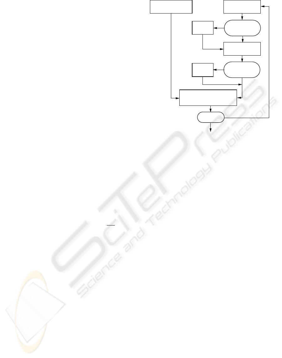
flowchart of the PSO algorithm is given in Fig. 1. A
swarm of particles, {U
(l)
i
}
S
i=1
, that represent poten-
tial solutions are evolved in the search space U
N×M
,
where S is the swarm size and index l denotes the it-
eration step. The algorithm is now summarised.
Update velocities
i
V
Modify
velocity
Velocity
approaches zero
or out of limits?
Yes
No
U
Update positions
(l)
i
out of bounds?
positionModify
position
Yes
No
Initialise particles
{
i
}
S
i=1
Evaluate costs
{F( )
i
}
i=1
update{ }
Yes
Output solution Gb
No
i=1
U
S
S
Terminate?
l=l+1
A new iteration
(l)
i
Pb
and
(l)
l=0
U
(0) (l)
(l)
Gb
Figure 1: Flowchart of the PSO algorithm.
2.1 PSO Algorithm
a) Initialisation. Set l = 0 and randomly generate the
initial particles, {U
(l)
i
}
S
i=1
, in the search space U
N×M
.
b) Evaluation. Each particle U
(l)
i
has an associated
cost F
¡
U
(l)
i
¢
, and it remembers its best position vis-
ited so far, denoted as Pb
(l)
i
, which provides the cog-
nitive information. Every particle also knows the best
position visited so far among the entire swarm, de-
noted as Gb
(l)
, which provides the social information.
The cognitive information {Pb
(l)
i
}
S
i=1
and the social
information Gb
(l)
are updated at each iteration given
the new cost information {F
¡
U
(l)
i
¢
}
S
i=1
.
c) Update. Each particle U
(l)
i
has a velocity, denoted
as V
(l)
i
, to direct its “flying” or search. The velocity
and position of the ith particle are updated in each
iteration according to:
V
(l+1)
i
= ξ ∗V
(l)
i
+ c
1
∗ϕ
1
∗(Pb
(l)
i
−U
(l)
i
)
+c
2
∗ϕ
2
∗(Gb
(l)
−U
(l)
i
), (4)
U
(l+1)
i
= U
(l)
i
+ V
(l+1)
i
, (5)
where ξ is the inertia weight, c
1
and c
2
are the two
acceleration coefficients, while ϕ
1
= rand() and ϕ
2
=
rand() denotes the two random variables uniformly
distributed in (0, 1).
In order to avoid excessive roaming of particles
beyond the search space, a velocity space V
N×M
with
V =
£
−V
max
, V
max
¤
+ j
£
−V
max
, V
max
¤
(6)
BIOSIGNALS 2010 - International Conference on Bio-inspired Systems and Signal Processing
54
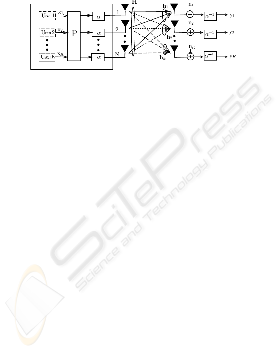
Figure 2: MUT-aided MIMO system with linear precoding, where the BS employs N transmit antennas to communicate with
K single-receive-antenna mobile devices.
is imposed so that each element of V
(l+1)
i
is within the
search range V defined in (6). Furthermore, if an ele-
ment of V
(l+1)
i
approaches zero, it may be randomly
reinitialised within the velocity range V. Similarly, if
a particle U
(l+1)
i
moves to outside the search space, it
is moved back inside U
N×M
randomly.
d) Termination. If the maximum number of iterations,
I
max
, is reached, terminate with the solution U
opt
=
Gb
(I
max
)
; otherwise, set l = l + 1 and go to Step b).
2.2 PSO Algorithmic Parameters
The search limit U
max
is specified by the problem con-
sidered, while the velocity limit V
max
is typically re-
lated to U
max
. Three common choices of the inertia
weight are ξ = 0, setting ξ to a small positive con-
stant, and ξ = rand(). The time varying acceleration
coefficients (Ratnaweera et al., 2004), in which c
1
is
reduced from 2.5 to 0.5 and c
2
varies from 0.5 to 2.5
during the iterative procedure according to
c
1
= (0.5 −2.5) ∗l/I
m
+ 2.5,
c
2
= (2.5 −0.5) ∗l/I
m
+ 0.5,
(7)
usually works well. Appropriate values for S and
I
max
can be chosen to ensure that the algorithm con-
verges to the optimal solution with a minimum com-
putational complexity.
Let the complexity of one cost function evaluation
be C
single
. With the swarm size S and assuming that
the algorithm converges in I
max
iterations, the number
of cost function evaluations is N
total
= S ×I
max
, and
the complexity of the algorithm is given by
C
PSO
= N
total
×C
single
= S ×I
max
×C
single
. (8)
3 LINEAR MBER MUT DESIGN
Our first application involves the PSO aided linear
MBER MUT design.
3.1 Linear MUT System Model
The linear MUT-aided MIMO system is depicted in
Fig. 2, where the BS equipped with N transmit an-
tennas communicates with K MSs, each employing a
single-receive antenna. The information symbol vec-
tor transmitted is given by x = [x
1
x
2
···x
K
]
T
, where
x
k
denotes the transmitted symbol to the kth MS and
it takes the value from the 4-QAM symbole set
S =
n
±
1
2
± j
1
2
o
. (9)
The MUT’s N ×K precoder matrix P is defined by
P = [p
1
p
2
···p
K
], (10)
where p
k
, 1 ≤k ≤K, is the precoder’s coefficient vec-
tor for the kth user’s data stream. Given a fixed total
transmit power E
T
at the BS, an appropriate scaling
factor should be used to fullfill this transmit power
constraint, which is defined as α =
p
E
T
/kPxk
2
.
At the receiver, the reciprocal of α is used to scale
the received signal to ensure unity-gain transmission.
The MIMO channel matrix H is given by
H = [h
1
h
2
···h
K
], (11)
where h
k
= [h
1
,
k
h
2
,
k
···h
N
,
k
]
T
, 1 ≤ k ≤ K, is the kth
user’s spatial signature. The channel taps h
i,k
for
1 ≤ k ≤ K and 1 ≤ i ≤ N are independent of each
other and obey the complex-valued Gaussian distribu-
tion with E[|h
i,k
|
2
] = 1. The additive white Gaussian
noise vector n is defined by n = [n
1
n
2
···n
K
]
T
, where
n
k
, 1 ≤ k ≤ K, is a complex-valued Gaussian white
noise with E[|n
k
|
2
] = 2σ
2
n
= N
o
. The signal-to-noise
ratio (SNR) of the system is defined as SNR = E
b
/N
o
,
where E
b
= E
T
/(Nlog
2
M ) is the energy per bit per
antenna for M -ary modulation. For the 4-QAM case
M = 4. The system model is given by
y = H
T
Px + α
−1
n, (12)
where y = [y
1
y
2
···y
K
]
T
denotes the received signal
vector, and y
k
, 1 ≤ k ≤K, constitutes sufficient statis-
PARTICLE SWARM OPTIMISATION AIDED MULTIUSER TRANSMISSION SCHEMES FOR MIMO
COMMUNICATION
55
tics for the kth MS to detect the transmitted data sym-
bol x
k
. Thus, the kth MS equipped with a conventional
matched filter can simply estimate x
k
by quantising y
k
.
3.2 Linear MBER MUT Design
Given the 4-QAM symbol vector x, the average BER
of the in-phase component of y at the receivers is
(Habendorf and Fettweis, 2007)
P
e
I
,x
=
1
K
K
∑
k=1
Q
µ
sgn(ℜ[x
k
])ℜ[h
T
k
Px]
σ
n
, (13)
where Q(•) is the standard Gaussian error function.
Similarly, given the symbol vector x, the average BER
of the quadrature-phase component of y is
P
e
Q
,x
=
1
K
K
∑
k=1
Q
µ
sgn(ℑ[x
k
])ℑ[h
T
k
Px]
σ
n
. (14)
Thus, the resultant BER for the specific 4-QAM sym-
bol x is
P
e,x
(P) =
¡
P
e
I
,x
(P) + P
e
Q
,x
(P)
¢
/2. (15)
Therefore, the MBER-MUT design is defined as the
solution of the following constrained optimisation
P
MBER,x
= arg min
P
P
e,x
(P) (16)
s.t. kPxk
2
= E
T
.
This constrained nonlinear optimisation is typically
solved by an iterative gradient based algorithm known
as the SQP (Habendorf and Fettweis, 2007). The SQP
based design however has a high computational com-
plexity. A PSO-aided design (Yao et al., 2009b) offers
an attractive low-complexity alternative.
A penalty function approach is adopted to con-
vert the constrained optimisation (16) into an uncon-
strained one which automatically meets the transmit
power constraint. First define the cost function
F(P) = P
e,x
(P) + G
x
(P) (17)
with the penalty function given by
G
x
(P) =
½
0, kPxk
2
−E
T
≤ 0
λ(kPxk
2
−E
T
), kPxk
2
−E
T
> 0
(18)
where the penalty factor λ > 0 should be chosen ap-
propriately so that the MBER-MUT design (16) be-
comes the following unconstrained optimisation
P
MBER,x
= arg min
P
F(P), (19)
where the precoding matrix P ∈ U
N×K
. The PSO al-
gorithm described in Section 2 can readily be adopted
to solve this optimisation problem. For the system in-
troduced in Subsection 3.1, our empirical results sug-
gest that the search limit can be set to U
max
= 1 while
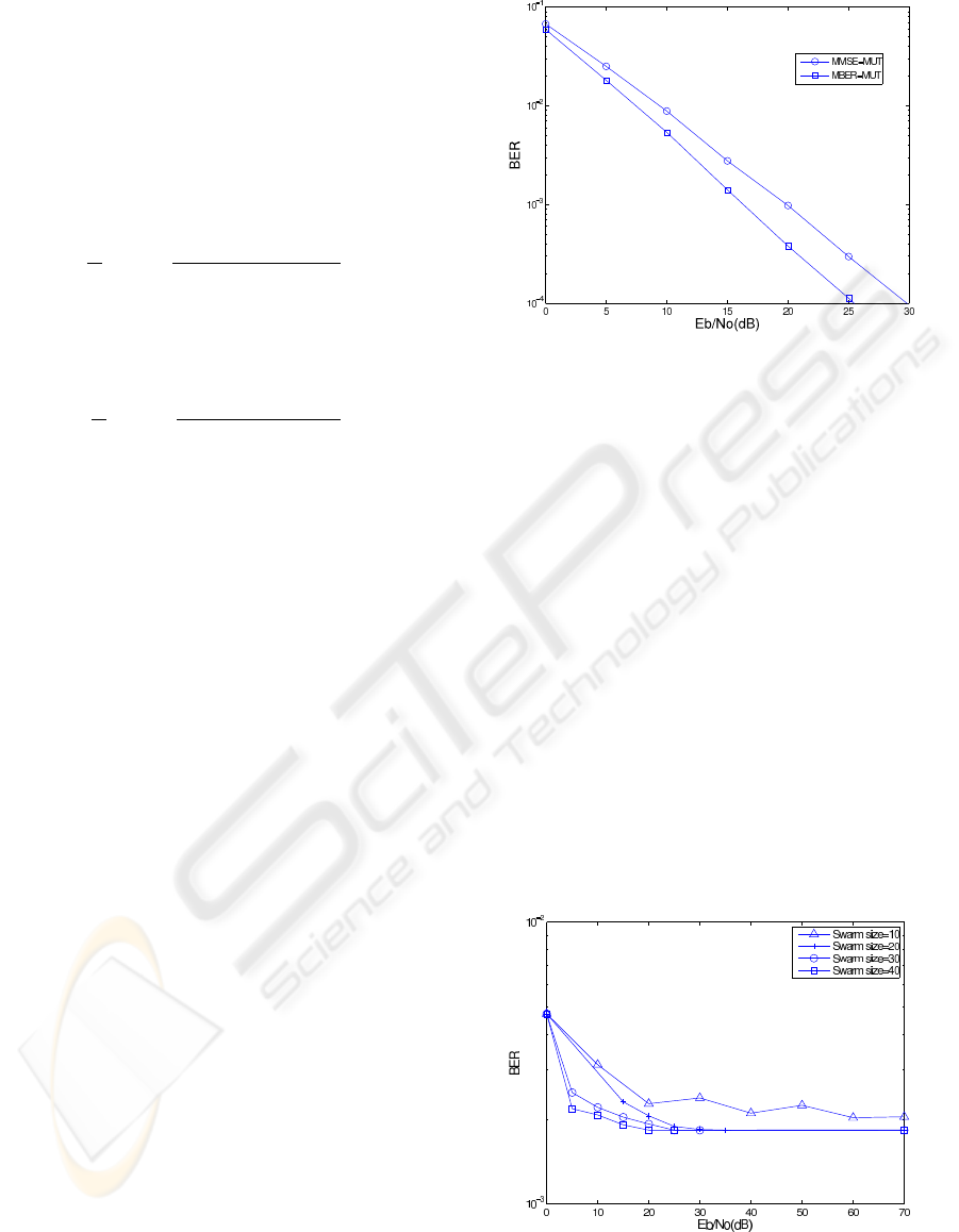
Figure 3: BER performance of the PSO-aided linear
MBER-MUT design for the 4 ×4 MIMO system, in com-
parison with the benchmark MMSE-MUT.
the velocity limit can be set to V
max
= 1. We also
remove the influence of the previous velocity by set-
ting ξ = 0, which works well for this application. In
Step a), one of the initial particles is set to the MMSE-
MUT solution (Habendorf and Fettweis, 2007).
3.3 Simulation Results
The MIMO system considered employed N = 4 trans-
mit antennas at the BS to communicate with K = 4
MSs. All the simulation results were obtained by av-
eraging over 100 channel realisations. An appropri-
ate swarm size was found to be S = 20 empirically.
The maximum number of iterations, I
max
, was so cho-
sen such that the PSO-based linear MBER-MUT al-
gorithm with the chosen I
max
and S = 20 arrived at
the same MBER performance also achieved by the
SQP-based MBER-MUT design. The value of I
max
was in the range of 20 to 30, depending on the value
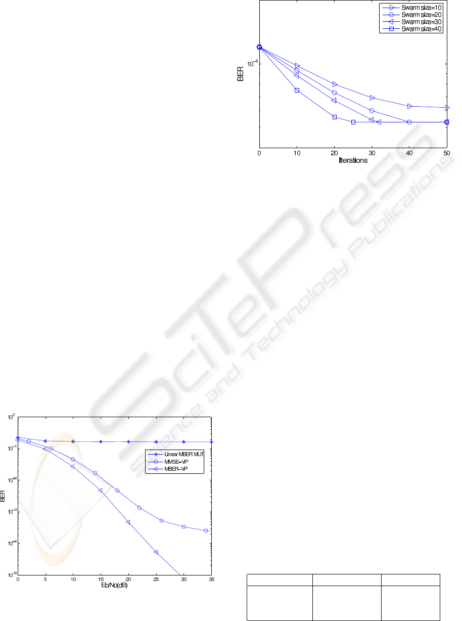
Figure 4: Convergence of the PSO MBER-MUT scheme
with different swarm sizes for the 4×4 MIMO system given
SNR= 15 dB.
BIOSIGNALS 2010 - International Conference on Bio-inspired Systems and Signal Processing
56
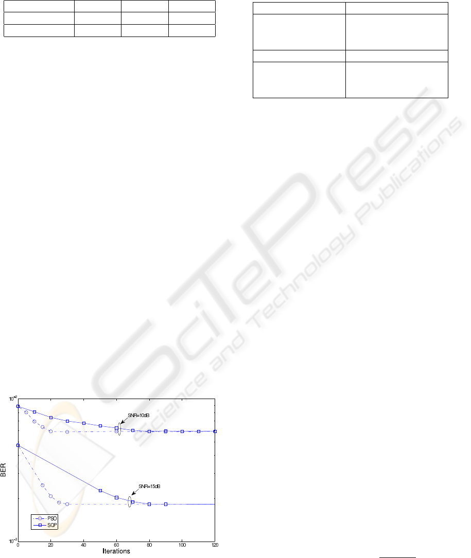
Table 1: Complexity (Flops) of the PSO aided linear
MBER-MUT design with different swarm sizes for the 4×4
MIMO system given SNR= 15 dB.
Swarm size S 20 30 40
Iterations I
max
30 25 20
C
PSO
(Flops) 402,840 503, 450 536,960
of the channel SNR. Fig. 3 compares the BER perfor-
mance of the linear MMSE-MUT scheme with those
of the PSO-aided linear MBER-MUT design, where
it can be seen that the PSO-aided MBER-MUT de-
sign achieved an SNR gain of 4.5 dB over the MMSE-
MUT benchmark at the target BER of 10
−4
.
Given SNR= 15 dB, convergence performance of
the PSO-aided linear MBER-MUT scheme with dif-
ferent swarm sizes are plotted in Fig. 4. It is clear
from Fig. 4 that S = 10 was insufficient for the PSO
to attain the optimal solution, while the PSO algo-
rithm with S = 20, 30 and 40 all converged to the
optimal solution after I
max
= 30, 25 and 20, respec-
tively. The complexity C
PSO
of the PSO-aided linear
MBER-MUT scheme for these three values of S are
listed in Table 1. We can see that the choice of
S
=
20
was optimal for this case, in terms of complexity.
Computational complexity of the PSO-aided lin-
ear MBER-MUT scheme was then compared with
that of the SQP-based one. Fig. 5 compares the con-
vergence performance of the SQP and PSO based
schemes, operating at the SNR values of 10 dB and
15 dB, respectively. It can be seen from Fig. 5 that
in the case of SNR= 10 dB, the SQP and PSO algo-
rithms converged to the optimal solution after 70 and
20 iterations, respectively, while at SNR= 15 dB, the
SQP and PSO algorithms arrived at the optimal solu-
tion after 80 and 30 iterations, respectively. The com-
Figure 5: Convergence performance comparison of the
PSO-aided and SQP-based MBER-MUT schemes for the
4 ×4 MIMO system given two SNR values.
Table 2: Complexity (Flops) and recorded run time (s) com-
parison of the PSO and SQP aided linear MBER-MUT de-
signs for the 4 ×4 MIMO system given two SNR values.
(SNR= 10 dB) SQP PSO
Iterations 70 20
Complexity (Flops) 3,180,170 268,560
Run time (s) 7412.1 664.9
(SNR= 15 dB) SQP PSO
Iterations 80 30
Complexity (Flops) 3,634,480 402,840
Run time (s) 8457.3 957.4
plexity and recorded run times for the two designs are
listed in Table 2. It can be seen from Table 2 that
the PSO-aided linear MBER-MUT design imposed
an approximately twelve times lower complexity than
the SQP counterpart at SNR= 10 dB, while it imposed
an approximately nine times lower complexity than
the SQP counterpart for the SNR value of 15 dB.
4 NONLINEAR MBER MUT
DESIGN
Our second application considers the PSO aided non-
linear MBER generalised VP design.
4.1 Generic VP System Model
The nonlinear MUT-aided MIMO system is depicted
in Fig. 6, where the BS employs N transmit antennas
to communicate with K single-antenna MS receivers
each employing a modulo device. The channel ma-
trix H, the information symbol vector x, and the noise
vector n are as defined in Subsection 3.1. Given x and
H, the generic VP generates the continuous-valued ef-
fective symbol vector d = [d
1
d
2
···d
N
]
T
, in order to
mitigate multiuser interference. In a conventional VP
design, d is expressed as
d = P(x + ω), (20)
where P is the N ×K precoding matrix and ω the
K-element discrete-valued perturbation vector. The
powerful MMSE VP scheme (Schmidt et al., 2005)
determines the MMSE solution for P and seeks ω
based on the MMSE criterion. Our proposed gener-
alised VP scheme, however, does not determine P and
ω. Rather it directly determines d.
Given a fixed total transmit power E
T
at the BS, an
appropriate scaling factor, α =
p
E
T
/kdk
2
, is used to
fullfill this transmit power constraint. At the receiver,
the reciprocal of α is used to scale the received signal
in order to maintain a unity-gain transmission. The
PARTICLE SWARM OPTIMISATION AIDED MULTIUSER TRANSMISSION SCHEMES FOR MIMO
COMMUNICATION
57
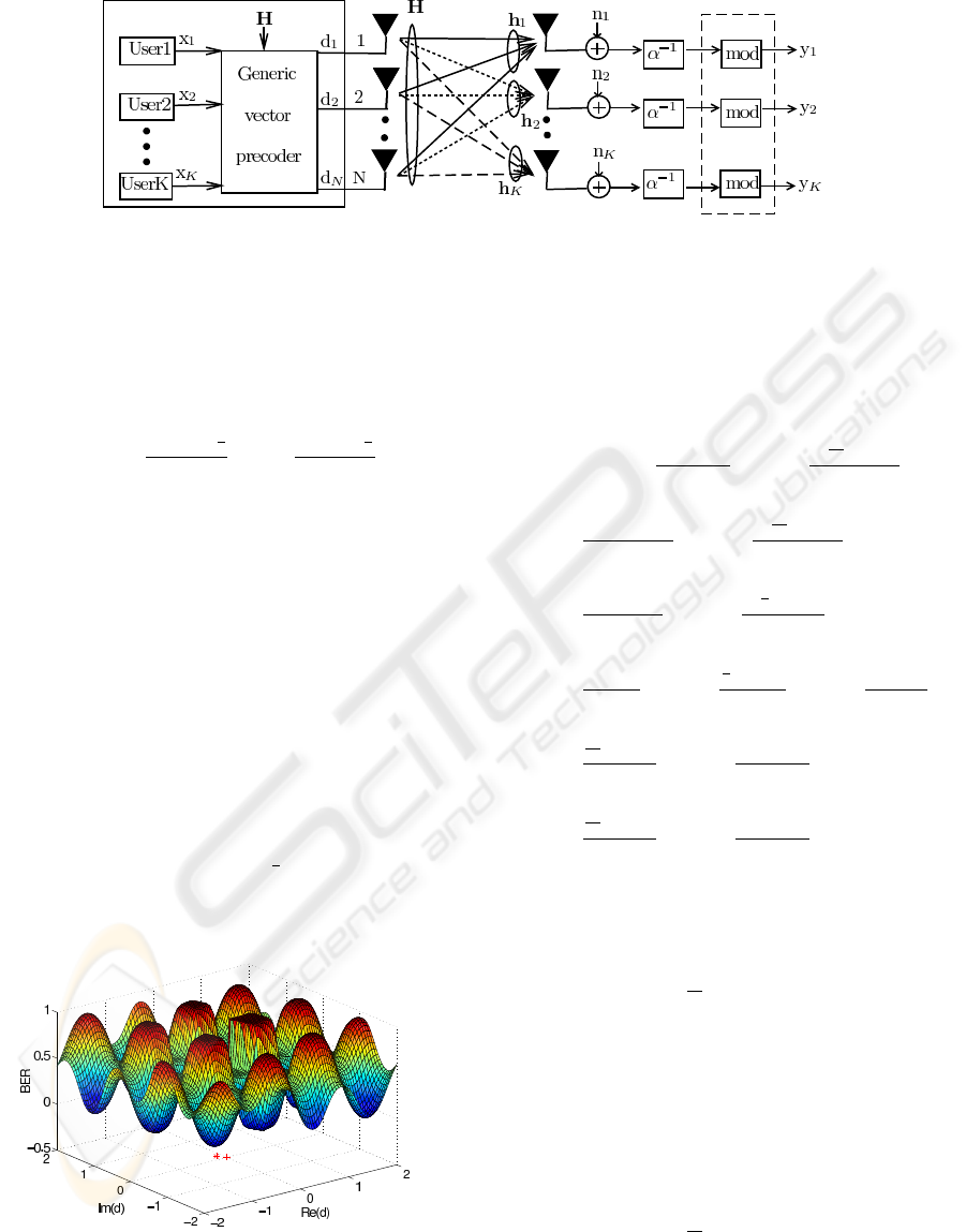
Figure 6: MUT-aided MIMO system with nonlinear VP, where the BS employs N transmit antennas to communicate with K
MSs each equipped with a modulo device.
received signal vector
ˆ
y = [ ˆy
1
ˆy
2
··· ˆy
K
]
T
before the
modulo operation is given by
ˆ
y = H
T
d + α
−1
n. (21)
The modulo operation invoked for ˆy
k
is described by
mod
τ
¡
ˆy
k
¢
= ˆy
k
−b
ℜ[ ˆy
k
] +
τ
2
τ
cτ − j b
ℑ[ ˆy
k
] +
τ
2
τ
cτ, (22)
where b•c denotes the integer floor operator, and τ
is a positive number determined by the modulation
scheme. The received signal vector y = [y
1
y
2
···y
K
]
T
after the modulo operation is given by
y = mod
τ
¡
ˆ
y
¢
, (23)
and y
k
, 1 ≤ k ≤ K, constitutes sufficient statistics for
the kth MS to detect the transmitted information data
symbol x
k
. The work (Hochwald et al., 2005) sug-
gested to choose τ according to
τ = 2(|c|
max
+ ∆/2), (24)
where |c|
max
is the largest distance of the modulated
symbols to the real or imaginary axis, and ∆ is the
spacing between the constellation points. For the 4-
QAM constellation (9), |c|
max
=
1
2
and ∆ = 1, which
leads to τ = 2 according to (24). The modulo operator
(22) maps the received signal, ℜ[ ˆy
k
] and ℑ[ ˆy
k
], into
the interval [−τ/2, τ/2).
Figure 7: BER surface as a function of the effective sym-
bol vector d for the 4-QAM system with N = 1 and K = 1,
given SNR= 16 dB. The mark ∗ is the MBER generalied
VP solution while the mark + is the MMSE VP solution.
4.2 MBER Generalised VP Design
The BER encountered at the output of the receiver af-
ter the modulo operation for the in-phase component
of user k can be expressed as (Yao et al., 2010)
P
e
I
,k
(d) ≈ Q
Ã
c
(k)
R
+ 3τ
α
−1
σ
n
!
+ Q
Ã
−
5τ
2
−c
(k)
R
α
−1
σ
n
!
− Q
Ã
−2τ −c
(k)
R
α
−1
σ
n
!
+ Q
Ã
−
3τ
2
−c
(k)
R
α
−1
σ
n
!
− Q
Ã
−τ −c
(k)
R
α
−1
σ
n
!
+ Q
Ã
−
τ
2
−c
(k)
R
α
−1
σ
n
!
− Q
Ã
−c
(k)
R
α
−1
σ
n
!
+ Q
Ã
τ
2
−c
(k)
R
α
−1
σ
n
!
−Q
Ã
τ −c
(k)
R
α
−1
σ
n
!
+ Q
Ã
3τ
2
−c
(k)
R
α
−1
σ
n
!
−Q
Ã
2τ −c
(k)
R
α
−1
σ
n
!
+ Q
Ã
5τ
2
−c
(k)
R
α
−1
σ
n
!
−Q
Ã
3τ −c
(k)
R
α
−1
σ
n
!
, (25)
where c
(k)
R
= sgn(ℜ[x
k
])ℜ[h
T
k
d]. Hence, the average
BER of the in-phase component of y is given by
P
e
I
,x
(d) =
1
K
K
∑
k=1
P
e
I
,k
(d). (26)
Similarly, let c
(k)
I
= sgn(ℑ[x
k
])ℑ[h
T
k
d]. The BER of
the quadrature-phase component for the kth user, de-
noted as P
e
Q
,k
(d), can be derived by replacing c
(k)
R
with c
(k)
I
in (25). Then the average BER for the
quadrature-phase component of y is given by
P
e
Q
,x
(d) =
1
K
K
∑
k=1
P
e
Q
,k
(d). (27)
The resultant average BER of y is given by
P
e,x
(d) = (P
e
I
,x
(d) + P
e
Q
,x
(d))/2. (28)
BIOSIGNALS 2010 - International Conference on Bio-inspired Systems and Signal Processing
58
Hence, the optimal effective symbol vector d
opt
is
found by solving the following optimisation problem
d
opt
= arg min
d
P
e,x
(d). (29)
The problem (29) turns out to be a challenging
non-convex optimisation with many local minima. As
an illustration, Fig. 7 depicts the BER surface P
e,x
(d)
for the simplest case of N = 1 and K = 1, with SNR=
16 dB. The PSO algorithm of Section 2 offers an effi-
cient means to solve this optimisation problem, where
the cost function is P
e,x
(d) with the parameter vec-
tor d ∈ U
N
. For the system given in Subsection 4.1,
our empirical results suggested that U
max
= 1.2 and
V
max
= 0.2 are appropriate. The inertia weight is cho-
sen as ξ = rand(), which is seen to perform better in
this application than the two alternative choices of ξ.
In Step a), one of the initial particles is set to the im-
proved MMSE-VP solution of (Yao et al., 2009a).
4.3 Simulation Results
We consider the challenging MIMO system, where
the BS employed N = 2 transmit antennas to com-
municate with K = 4 MSs. This system was rank de-
ficient as the number of the BS transmit antennas was
smaller than the number of MSs supported. Again,
all the simulation results were obtained by averag-
ing over 100 channel realisations. The received sig-
nals after the modulo operation were directly used for
making decisions. Appropriate swarm size was found
empirically to be S = 20, and the maximum number of
iterations was ranging from I
max
= 20 to 45 depend-
ing on the SNR value. Fig. 8 shows the BER perfor-
mance of the linear MBER-MUT design presented in
Figure 8: Performance comparison of the linear MBER-
MUT, the nonlinear MMSE-VP and the proposed PSO-
aided MBER generalised VP for the 2 ×4 MIMO system.
Figure 9: Convergence of the PSO-aided MBER gener-
alised VP scheme with different swarm sizes for the 2 ×4
MIMO system given SNR= 25 dB.
Section 3, the powerful nonlinear MMSE-VP design
presented in (Schmidt et al., 2005), and the proposed
PSO-aided MBER generalised VP design. The lin-
ear MBER MUT encountered a high error floor as it
was unable to differentiate the users’ information in
this demanding scenario. The nonlinear MMSE VP
scheme showed a much better performance but still
sufferred from an error floor as can be seen in Fig. 8.
By contrast, the generalised MBER VP outperformed
the MMSE VP and it did not exhibit a visible error
floor which showed its ability to operate successfully
in the rank-deficient scenario.
Fig. 9 shows that S = 10 was insufficient for the
PSO algorithm to attain the global optimal solution,
while the PSO algorithm with S = 20, 30 and 40 all
converged to the optimal solution with I
max
= 40, 32
and 25, respectively. The computational complexity
C
PSO
for the PSO algorithm with S = 20, 30 and 40
are compared in Table 3, which demonstrated that the
choice of the swarm size S = 20 for the PSO algo-
rithm was optimal in terms of complexity in this case
and explained why we used S = 20 in the simula-
tion. The computational complexity (Flops) as well
as the recorded run times (s) of the two nonlinear
MUT designs, namely the powerful MMSE-VP so-
lution (Schmidt et al., 2005) and the proposed PSO-
Table 3: Complexity (Flops) of the PSO aided MBER gen-
eralised VP design with different swarm sizes for the 2 ×4
MIMO system, given SNR= 25 dB.
Swarm size S Iterations I
max
Complexity
20 40 4,064,937
30 32 4,149,627
40 25 4,174,077
PARTICLE SWARM OPTIMISATION AIDED MULTIUSER TRANSMISSION SCHEMES FOR MIMO
COMMUNICATION
59

Table 4: Complexity (Flops) and recorded run time (s) re-
quired by the MMSE-VP design and the PSO-aided MBER
generalised VP design for the 2 ×4 MIMO system given
two SNR values.
(SNR= 25 dB) MMSE-VP MBER-VP
Complexity (Flops) 2, 508,638 4,064,937
Run time (s) 4787.3 8878.9
(SNR= 30 dB) MMSE-VP MBER-VP
Complexity (Flops) 2, 609,600 4,471,060
Run time (s) 4981.9 9565.8
aided MBER generalised VP solution, are compared
in Table 4, given the two SNR values. It can be seen
from Table 4 that the complexity of the PSO aided
MBER generalised VP design was no more than twice
of the conventional MMSE-VP design. This was a
small price worthy of paying, considering the signifi-
cant performance enhancement of the former over the
latter as shown in Fig. 8.
5 CONCLUSIONS
PSO has been invoked for designing optimal MUT
schemes for MIMO communication systems. Our
investigation has demonstrated that PSO aided de-
signs are capable of attaining global or near global
optimal solutions at affordable computational costs.
More specifically, the PSO aided linear MBER MUT
scheme has been shown to impose significantly lower
computational complexity than the existing state-of-
the-art SQP-based linear MBER MUT design, while
a novel PSO aided nonlinear MBER generalised VP
design has been demonstrated to outperform the pow-
erful nonlinear MMSE VP solution at the cost of
slightly increased complexity.
REFERENCES
Alias, M. Y., Chen, S., and Hanzo, L. (2005). Multi-
ple antenna aided ofdm employing genetic algorithm
assisted minimum bit error rate multiuser detection.
IEEE Trans. Vehicular Technology, 54:1713–1721.
Chen, S. and Wu, Y. (1998). Maximum likelihood joint
channel and data estimation using genetic algorithms.
IEEE Trans. Signal Processing, 46:1469–1473.
Chen, S., Wu, Y., and McLaughlin, S. (1997). Genetic al-
gorithm optimisation for blind channel identification
with higher-order cumulant fitting. IEEE Trans. Evo-
lutionary Computation, 1:259–266.
Feng, H.-M. (2006). Self-generation rbfns using evolutional
pso learning. Neurocomputing, 70:241–251.
Guru, S. M., Halgamuge, S. K., and Fernando, S. (2005).
Particle swarm optimisers for cluster formation in
wireless sensor networks. In Proc. 2005 Int. Conf.
Intelligent Sensors, Sensor Networks and Information
Processing, pages 319–324, Melbourne, Australia.
Habendorf, R. and Fettweis, G. (2007). Nonlinear optimiza-
tion for the multiuser downlink. In Proc. 13th Euro-
pean Wirelss Conf., page 7 pages, Paris, France.
Hochwald, B. M., Peel, C. B., and Swindlehurst, A. L.
(2005). A vector-perturbation technique for near-
capacity multiantenna multiuser communication - part
ii: perturbation. IEEE Trans. Communications,
53:537–544.
Kennedy, J. and Eberhart, R. (1995). Particle swarm opti-
mization. In Proc. 1995 Int. Conf. Neural Networks,
volume 4, pages 1942–1948, Perth, Australia.
Kennedy, J. and Eberhart, R. C. (2001). Swarm Intelligence.
Morgan Kaufmann.
Nocedal, J. and Wright, S. (1999). Numerical Optimization.
Springer, New York.
Ratnaweera, A., Halgamuge, S. K., and Watson, H. C.
(2004). Self-organizing hierarchical particle swarm
optimizer with time-varying acceleration coefficients.
IEEE Trans. Evolutionary Computation, 8:240–255.
Schmidt, D. A., Joham, M., and Utschick, W. (2005). Min-
imum mean square error vector precoding. In Proc.
PIMRC 2005, volume 1, pages 107–111, Berlin, Ger-
many.
Soo, K. K., Siu, Y. M., Chan, W. S., Yang, L., and
Chen, R. S. (2007). Particle-swarm-optimization-
based multiuser detector for cdma communications.
IEEE Trans. Vehicular Technology, 56:3006–3013.
Voj
˘
ci
´
c, B. R. and Jang, W. M. (1998). Transmitter precod-
ing in synchronous multiuser communications. IEEE
Trans. Communications, 46:1346–1355.
Xu, C., Hu, B., Yang, L.-L., and Hanzo, L. (2008a). Ant-
colony-based multiuser detection for multi-functional
antenna array assisted mc ds-cdma systems. IEEE
Trans. Vehicular Technology, 57:658–663.
Xu, C., Yang, L.-L., Maunder, R. G., and Hanzo,
L. (2008b). Near-optimum soft-output ant-colony-
optimization based multiuser detection for the ds-
cdma. In Proc. ICC 2008, pages 795–799, Beijing,
China.
Yao, W., Chen, S., and Hanzo, L. (2009a). Improved mmse
vector precoding based on the mber criterion. In Proc.
VTC2009-Spring, page 5 pages, Barcelona, Spain.
Yao, W., Chen, S., and Hanzo, L. (2010). Generalised
vector precoding design based on mber criterion for
multiuser transmission. In VTC 2010-Spring, Taipei,
China, submitted.
Yao, W., Chen, S., Tan, S., and Hanzo, L. (2009b). Mini-
mum bit error rate multiuser transmission designs us-
ing particle swarm optimisation. IEEE Trans. Wireless
Communications, 8:5012–5017.
Yen, K. (2001). Genetic Algorithm Assisted CDMA Mul-
tiuser Detection. PhD thesis, School of Electronics
and Computer Science, University of Southampton,
Southampton, UK.
BIOSIGNALS 2010 - International Conference on Bio-inspired Systems and Signal Processing
60
