
A MORPHING WING USED SHAPE MEMORY ALLOY
ACTUATORS NEW CONTROL TECHNIQUE WITH
BI-POSITIONAL AND PI LAWS OPTIMUM COMBINATION
Part 1: Design Phase
Teodor Lucian Grigorie, Andrei Vladimir Popov, Ruxandra Mihaela Botez
École de Technologie Supérieure, Montréal, Québec H3C 1K3, Canada
Mahmoud Mamou, Youssef Mébarki
National Research Council, Ottawa, Ontario K1A 0R6, Canada
Keywords: Morphing Wing, Shape Memory Alloy Actuators, Bi-positional and PI Control Design, Numerical
Simulations.
Abstract: The paper presents the design phase of the actuators control system development for a morphing wing
application. Some smart materials, like Shape Memory Alloy (SMA), are used as actuators to modify the
upper surface of the wing made of a flexible skin. The actuations lines control is designed and validated
using a numerical simulation model developed in Matlab/Simulink. The finally adopted control law is a
combination of a bi-positional law and a PI law; the control must behave like a switch between cooling
phase and heating phase, situations where the output current is 0 A, or is controlled by a law of PI type. The
PI controller, for the heating phase, is optimally tuned using the Ziegler-Nichols criterion and the linear
model obtained using the System Identification Toolbox of Matlab. The controlled linearized system for
heating phase is numerically tested in terms of time response, stability, controllability and the observability.
In the actuation control design final phase, numerical simulations, based on SMA non-linear analytical
model, were used for validation.
1 INTRODUCTION
Many researches are made around the world in the
new challenge field related to the morphing aircraft,
with the purpose to improve operational efficiency,
particularly by reducing fuel consumption (Chang,
2009, Smith, 2007, Hinshaw, 2009, Gonzalez, 2005,
Namgoong, 2006, Majji, 2007, and Ruotsalainen,
2009). Therefore, a lot of architecture were and are
still imagined, designed, studied and developed, for
this new concept application. One of these is our
team project including the numerical simulations
and experimental multidisciplinary studies using the
wind tunnel for a morphing wing equipped with a
flexible skin, smart material actuators and pressure
sensors. The aim of these studies is to develop an
automatic system that, based on the information
related to the pressure distribution along the wing
chord, moves the transition point from the laminar to
the turbulent regime closer to the trailing edge in
order to obtain a larger laminar flow region, and, as
a consequence, a drag reduction.
The objective of here presented research work
was to develop an actuation control concept for a
new morphing mechanism using smart materials,
like Shape Memory Alloy (SMA), as actuators.
These actuators modify the flexible upper surface of
the wing, changing the airfoil shape. The morphing
wing project was developed by Ecole de
Technologie Supérieure in Montréal, Canada, in
collaboration with Ecole Polytechnique in Montreal
and the Institute for Aerospace Research at the
National Research Council Canada (IAR-NRC).
To achieve the aerodynamic imposed purpose, a
first phase of the studies involved the determination
of some optimized airfoils available for 35 different
flow conditions (five Mach numbers and seven
angles of attack combinations). The optimized
5
Lucian Grigorie T., Popov A., Mihaela Botez R., Mamou M. and Mébarki Y. (2010).
A MORPHING WING USED SHAPE MEMORY ALLOY ACTUATORS NEW CONTROL TECHNIQUE WITH BI-POSITIONAL AND PI LAWS OPTIMUM
COMBINATION - Part 1: Design Phase.
In Proceedings of the 7th International Conference on Informatics in Control, Automation and Robotics, pages 5-12
DOI: 10.5220/0002878400050012
Copyright
c
SciTePress

airfoils were derived from a laminar WTEA-TE1
reference airfoil (Khalid, 1993, and Khalid, 1993),
and were used as a starting point for the actuation
system design. The transition point position
estimation is made using the information received
from a pressure system sensors (optical and Kulite
types) equipping the upper face of the wing. Two
architectures were developed for morphing system:
open loop and closed loop. The difference between
the two architectures is given by using or not using
the position of transition point as a feedback signal
for the actuation lines control. Here described work
was developed in the open loop phase; in this phase
were made numerical and experimental studies
related to the aerodynamics of the morphed wing, to
the flexible skin realization, to the actuation system,
to the control of the actuation system, and, also, to
the real-time determination and visualization of the
transition point position using the pressure sensor
system. Here, the pressure sensors using is limited to
the monitoring of the pressure distribution and of the
RMS pressure distribution in the boundary layer.
2 ARCHITECTURE OF THE
CONTROLLED MORPHING
WING SYSTEM
The chosen wing model was a rectangular one, with
a reference airfoil WTEA-TE1, a chord of 0.5 m and
a span of 0.9 m. The model was equipped with a
flexible skin made of composite materials (layers of
carbon and Kevlar fibers in a resin matrix) morphed
by two actuation lines (Fig. 1). Each actuation line
uses SMA wires as actuators. In the same time, 32
pressure sensors (16 optical sensors and 16 Kulite
sensors), were disposed on the flexible skin in
different positions along of the chord. The sensors
are positioned on two diagonal lines at an angle of
15 degrees from centerline. The rigid lower structure
was made from Aluminum, and was designed to
allow space for the actuation system and wiring.
Actuation
lines
Cavities for
instrumentation
Flexible skin
(morphed extrados)
Rigid
intrados
Rigid part of
the extrados
Support plate for
actuation system
Leading
edge
Trailing
edge
Figure 1: General architecture of the mechanical model.
Starting from the reference airfoil, depending on
different flow conditions, 35 optimized airfoils were
calculated for the desired morphed positions of the
airfoil. The flow conditions were established as
combinations of seven incidence angles (-1˚, -0.5˚,
0˚, 0.5˚, 1˚, 1.5˚, 2˚) and five Mach numbers (0.2,
0.225, 0.25, 0.275, 0.3). Each of the calculated
optimized airfoils must be able to keep the transition
point as much as possible near the trailing edge.
The SMA actuator wires are made of nickel-
titanium, and contract like muscles when electrically
driven. Also, these have the ability to personalize the
association of deflections with the applied forces,
providing in this way a variety of shapes and sizes
extremely useful to achieve actuation system goals.
How the SMA wires provide high forces with the
price of small strains, to achieve the right balance
between the forces and the deformations, required
by the actuation system, a compromise must be
established. Therefore, the structural components of
the actuation system must be designed to respect the
capabilities of actuators to accommodate the
required deflections and forces.
Each of our actuation lines uses three shape
memory alloys wires (1.8 m in length) as actuators,
and contains a cam, which moves in translation
relative to the structure (on the x-axis in Fig. 2). The
cam causes the movement of a rod related on the
roller and on the skin (on the z-axis). The recall used
is a gas spring. So, when the SMA is heating the
actuator contracts and the cam moves to the right,
resulting in the rise of the roller and the
displacement of the skin upwards. In contrast, the
cooling of the SMA results in a movement of the
cam to the left, and thus a movement of the skin
down. The horizontal displacement of each actuator
is converted into a vertical displacement at a rate 3:1
(results a cam factor c
f
=1/3). From the optimized
airfoils, an approximately 8 mm maximum vertical
displacement was obtained for the rods, so, a 24 mm
maximum horizontal displacement must be actuated.
3 SMA ACTUATORS CONTROL
DESIGN AND NUMERICAL
SIMULATION
The control of SMA actuators can be achieved, in
principle, using any method of position control, but
the specific properties of SMA actuators, such as
hysteresis, the first cycle effect and the long term
changes must always be considered. Starting from
the established concept of the actuation system the
operating schema of the controller can be organized
ICINCO 2010 - 7th International Conference on Informatics in Control, Automation and Robotics
6

as is presented in Fig. 3. Based on the 35 studied
flight conditions a database of the 35 optimized
airfoils can be built. Therefore, for each flight
condition results a pair of optimal vertical
deflections (dY
1opt
, dY
2opt
) for the two actuation lines.
The SMA actuators morph the airfoil until the
obtained vertical deflections of the two actuation
lines (dY
1real
, dY
2real
) become equals with the
required deflections (dY
1opt
, dY
2opt
). The morphed
airfoil vertical deflections in the actuation points are
measured using two position transducers. The role of
the controller is to elaborate an electrical current
command signal for the SMA actuators on the base
of the error signals (e) between the required vertical
displacements and obtained displacements. Because
the two actuation lines are identical the designed
controller will be valid for both of them.
HeatingCooling
Three SMA wires
Flexible skin
Cam
Roller
Support plate for
actuation system
Rod
Compression
spring
x
z
Figure 2: The actuation mechanism concept.
, M,
Re
Pilot
Control
Flight
conditions
Optimised
airfoils
database
dY
1op t
dY
2op t
Real airfoil
Integrated
controller
dY
1real
dY
2real
SMA
actuators
e=dY
opt
- dY
real
Airflow
perturbations
Current
Position
transducers
dY
1real
dY
2real
Figure 3: Operating schema of the SMA actuators control.
The first phase of the controller design supposes
the numerical simulation of the controlled actuation
system. Therefore, a model of SMA actuator was
required. In our system a non-linear model was used
(a numerical finite element one) build by Prof. P.
Terriault using the theoretical model of Lickhatchev
(Terriault, 2006). The SMA model has as inputs the
initial temperature of the alloy, the electrical current
that heats the alloy and the applied force; the outputs
are the displacement of the actuator and the
temperature of the alloy during functioning.
According to this model, to use the shape-changing
characteristics the SMA needs to be initialized by an
external force, which obliges it to go initially
through the transformation phase and further to
revert to the initial phase through the cooling phase.
Before these two phases, the control can’t be
realized, due to the intrinsic behavior of the SMA
(Terriault, 2006, and Popov, 2008).
Looking the wing as an object moving through
the atmosphere, aerodynamic forces are generated
between the air and the wing; these forces vary in
function of the airflow characteristics (Mach
number, Reynolds number and α - angle of attack).
Since the aerodynamic forces are suction forces, it
tends to lift the skin and to shorten the SMA wire.
Against the aerodynamic forces action the elastic
force of the flexible skin. A gas spring is needed in
order to counteract the aerodynamic forces, so that
the resultant force that acts on the SMA wire is
given by equation
.)(
faeroskinspringSMA
cFFFF
(1)
To have the premises necessary to initialize the
SMA actuators in any conditions, they are loaded by
the gas spring even if there are no aerodynamic
forces applied on the flexible skin. So, the equation
(1) becomes
()(),
SMA pretension spring h skin v aero f
F
Fk kFc
(2)
where
.,
vskinskinhspringpretensionspring
kFkFF
(3)
F
SMA
is the SMA resultant force, F
spring
- gas spring
elastic force, F
skin
- elastic force produced by the
flexible skin, F
aero
- aerodynamic force, F
pretension
-
pretension force of the spring, c
f
- cam factor (1/3),
k
spring
and k
skin
are the elastic coefficients of the
spring, and of the skin, respectively, δ
h
and δ
v
are the
horizontal and vertical actuated displacements.
Implementing the SMA actuators model in a
Matlab S-function, the simulation model in Fig. 4
was obtained. As can be observed, to control the
SMA actuators, an adequate electrical current must
supply it. The length of the SMA wires is a complex
function of the SMA load force and temperature, the
last one being influenced by the supplying current in
time and by the interaction of the wires with the
environment in theirs cooling phase (when the
electrical supply is removed) (Grigorie, 2009).
Skin deflection (mm)
T [K]
SMA elongation x [m]
t [C deg]
1
1
1.8
SMA Initial
length [m]
XY Graph
(y vs. t)
y
To Workspace3
To Workspace2
x
To Workspace1
0
Skin deflection [mm]
Scope 2
Scope 1
0
SMA elongation [m]
Current
Force
Displacement
Temperature
SMA
F aero
x (m)
F SMA
y (mm)
Mechanical system
273.15
Kelvin
1500
Desired
Force aero
0
Desired
Current [A]
0
Current [A]
t
Figure 4: SMA actuators Simulink model.
A MORPHING WING USED SHAPE MEMORY ALLOY ACTUATORS NEW CONTROL TECHNIQUE WITH
BI-POSITIONAL AND PI LAWS OPTIMUM COMBINATION - Part 1: Design Phase
7
The block “Mechanical system” in Fig. 4 was
modeled accordingly with the equations (1) to (3).
As is shown in Fig. 2, the horizontal and the vertical
actuated distances are correlated by using the “cam
factor” c
f
=1/3. Therefore, the aerodynamic and the
skin forces (F
aero
and F
skin
) are reflected in the SMA
load force (F
SMA
) with the same rate. The gas spring
has a preloaded force of 1500 N and a linear elastic
coefficient of 2.95 N/mm. In simulations a linear
elastic coefficient of approximate 100 N/mm was
considered for the skin.
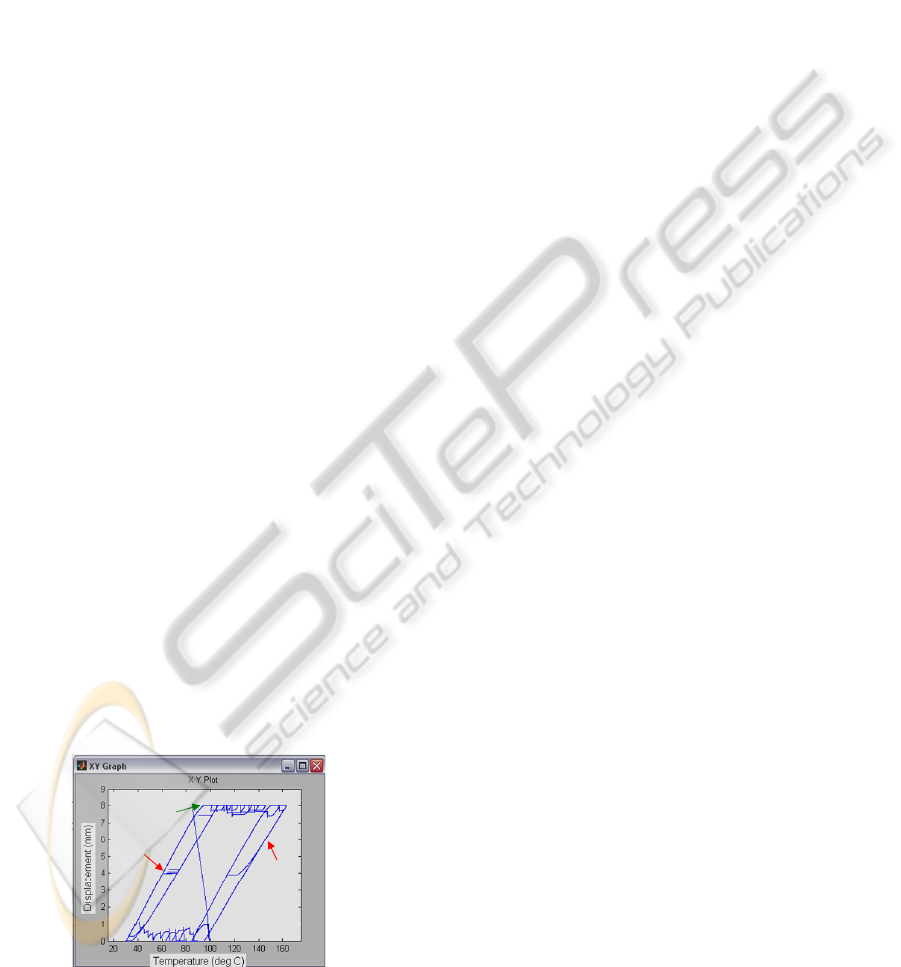
The envelope of the SMA actuator, obtained
through numerical simulation for different
aerodynamic load cases, is shown in Fig. 5. As can
be observed from Fig. 5, to obtain a skin maximum
vertical displacement (8 mm) in absence of
aerodynamic force, it is required a high temperature
(approximately 162˚C) in order to counteract the
spring force. Because the ability of the SMA wires
to contract is dependent upon Joule heating to
produce the transformation temperature required, the
need in higher temperature is reflected by a need in
higher electrical current. Due to the fact that the
aerodynamic forces reduce the actuators load the
required current and temperature values are
decreased; i.e. for F
aero
=1800 N the need in
temperature for the maximum vertical displacement
obtaining is approximately 90˚C. From other point
of view, the ability of the SMA wires to return to
their original configuration is dependant upon the
ability of the system to cool the wires. The simulated
SMA model offers just summary information about
this subject, the proper heating and cooling of the
wires being observed only in the moment of a
thermodynamic analysis of the physical morphing
wing. The system architecture play a big role in the
wire cooling by the convection process, and also the
performances of the system can be negatively
influenced by heat transfer from actuators to the
other components.
F
aero
= 0 N
F
aero
= 1800 N
Max
v
= 8 mm
Figure 5: Simulated envelope of the SMA actuator.
According with Fig. 3, the integrated controller
purpose is to control the SMA actuators in terms of
supply electrical current so that to cancel the
deviation e between the required values for vertical
displacements (corresponding to the optimized
airfoils) and the real values, obtained from position
transducers. As mentioned previously, the design of
such controller is difficult considering the strong
nonlinearities of the SMA actuators characteristics,
nonlinearities significantly influenced by the forces
with which they are tense. The chosen design
procedure consisted of the following steps:
Step 1: numerical simulation of the SMA model
actuators for certain values of the forces in the system;
Step 2: approximation of the system with linear
systems in the heating and cooling phases using the
System Identification Toolbox of Matlab and the
numerical values obtained at the Step 1;
Step 3: the choice of the controller type and its
tuning for each of the two SMA actuators phase –
heating and cooling;
Step 4: the integration of the two obtained controller
in a single one followed by its validation for the
general model of the system (non-linear).
Because the team that established the actuation
line architecture (Georges, 2009) suggested that the
pretension force of the gas spring must have the
value F
pretension
=1500 N, F
aero
= 1500 N value was
chosen in numerical simulations for the aerodynamic
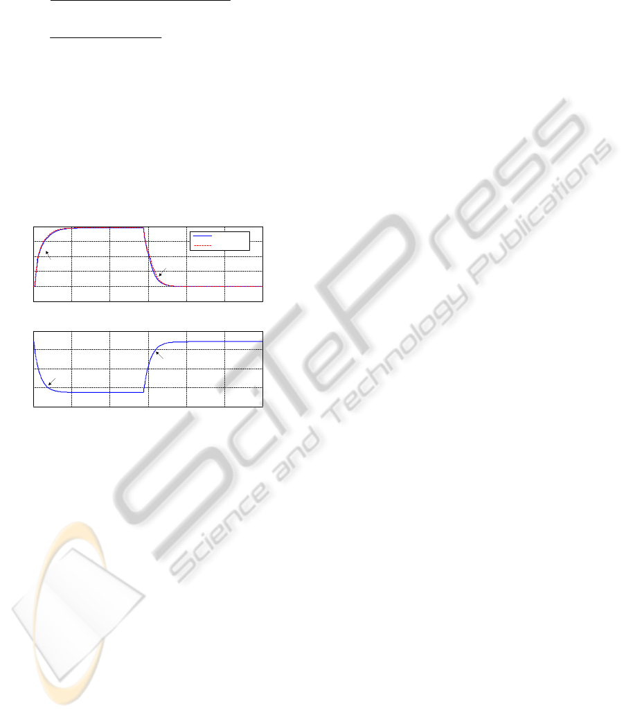
force. Simulating a cooling phase followed by a
heating phase with the model in Fig. 4, the blue
characteristics depicted in Fig. 6 were obtained. In
the first graphical window of the figure is presented
the SMA wire length changing in time (δ
h
), while in
the second window the SMA wire temperature
values in the two phases are shown. One observes
that a SMA wire dilatation results in the cooling
phase, and a wire contraction is obtained in the
heating phase. For a horizontal actuation distance of
approximately 24 mm the wire temperature reaches
a value near by 100˚C. Note are the transient time to
reach the steady-state values for the two phases:
approximate 60 s for the cooling phase and
approximate 40 s for the heating phase. For the
steady-state, after the cooling phase, the numerical
simulation obtained forces were: F
SMA
=1000 N,
F
skin
=0 N and F
spring
=1500 N. In this steady-state the
system is relaxed in terms of mechanical and the
vertical displacement of the actuator is null. For the
steady-state, after the cooling phase, the numerical
simulation obtained forces were: F
SMA
=1337 N,
F
skin
=266.1 N and F
spring
=1571 N. This steady-state
corresponds to the actuation system maximal
vertical displacement of approximately 8 mm.
Using the Matlab System Identification Toolbox
ICINCO 2010 - 7th International Conference on Informatics in Control, Automation and Robotics
8
and the numerical values characterizing the δ
h
response at a series of successive step inputs, two
transfer functions were found for the SMA phases:
2
32
2
0.0177388 s 0.004017 s 0.0241958
(s) ,
s 1.43582 s 0.64742 s 0.001018
0.3535 s 0.2672
(s) ,
s 1.9386 s 0.011242
h
c
H
H
(4)
where H
h
(s) and H
c
(s) are the transfer functions for
heating and cooling phases. The displacements δ
h
,
corresponding to the linear systems obtained through
the two phases identification, are depicted with red
line in Fig. 6. A very good approximation can be
also observed for the two phases through the
identification
in simulated conditions. The previously
established transfer functions help to the controller
type choice for each phase and to its tuning.
0 50 100 150 200 250 300
0
30
60
90
120
0 50 100 150 200 250 300
-6
0
6
12
18
24
heating
cooling
cooling
heating
SMA model
TF
Time [s]
Temperature [
o
C] Displacement
h
[mm]
F
aero
= 1500 N
Time [s]
Figure 6: Actuator displacement and temperature vs time.
Considering the significance of physical
controlled phenomenon, that the SMA wire must be
heated to contract and then cooled to dilate by
providing an appropriate electrical current by the
control block, it is normal that in the cooling phase
the actuators not be powered. This phase of cooling
may occur in controlling not only a long-term phase,
when it ordered a switch between two values of the
actuator displacements, but also as a short-lived
phase, which occurs when the real value of the
deformation exceeds its desired value and is need to
cool the actuator wires. On the other hand, it is
imperative that in the heating phase actuators to be
controlled so that the stationary error of the
automatic system to be zero. Therefore, for this
phase one opted for a simple architecture of the
controller of PI type (proportional-integral). It
combines the advantages of proportional type
controller, which reduces substantially the overshoot
and lead to a short transient time, with the benefits
of the integral controller, which cancels the steady-
state system error. As a consequence, the resulted
controller must behave like a switch between
cooling phase and heating phase, situations where
the output current is 0 A, or is controlled by a law of
PI type. The two phase’s interconnection leads to an
integrated controller, which can be viewed as a
combination of a bi-positional controller (an on-off
one) and a PI (proportional-integral) controller.
The input-output characteristic of a bi-positional
(on-off) controller can be described by the equation
,0if,
,0if,
)(
ei
ei
ti
m
m
(5)
where i(t) is the command variable (electrical
current in our case) in time, i
m
reflects the value of
the command and e is the operating error (Fig. 3).
The PI controller law is given by
,d)()()(
tteKteKti
IP
(6)
with K
P
- the proportional gain, and K
I
- the integral
gain. Combining the two controllers in a single one,
based on the rules previously mentioned results the
control law of the integrated controller as the form
.0if,d)()(
,0if,0
)(
etteKteK
e
ti
IP
(7)
The optimal tuning of the controller in heating
phase was realized using an integral criterion, the
error minimum surface criterion, very well known in
the literature as Ziegler-Nichols criterion (Mihoc,
1980); the tuning methodology is: a) the regulator is
considered as a proportional one (P) and it is tuned
with respect to the K
P
parameter; b) the
amplification factor K
P
is increased until the
response of the automatic system will be self-
sustained oscillatory. One memorizes the value K
P0
of K
P
for which the system has an oscillatory
behavior and the value of oscillations semi-period
(T
0
). The optimal values for the parameters of the PI
regulator are determined using the relations:
).85.0/(,45.0
00
TKKKK
PIPP
(8)
Follows the controller tuning steps the next
numerical values for the PI controller parameters
were obtained and/or were calculated:
.0061.787,8.1792
,s68.2,3984
00
IP
P
KK
TK
(9)
As a consequence, the controlled system in hea-
A MORPHING WING USED SHAPE MEMORY ALLOY ACTUATORS NEW CONTROL TECHNIQUE WITH
BI-POSITIONAL AND PI LAWS OPTIMUM COMBINATION - Part 1: Design Phase
9

ting phase can be modeled with an approximate
linear system with the block schema in Fig. 7. The
parameters a
0
÷a
2
and b
0
÷b
3
in the schema are the
coefficients of the H
h
(s) transfer function nominator
and denominator in ascending power of s (eq. (4)).
The open loop transfer function of the controlled
heating phase is
32
3210
432
3210
sss
(s) (s) (s) ,
ssss
ol PI h
qqqq
HCH
bbbb
(10)
while the closed loop transfer function is
32
3210
432
43210
sss
(s) (s) (s) .
ssss
cl PI h
qqqq
HCH
rrrrr
(11)
Current
SMA heating
model
01
2
2
3
3
01
2
2
sss
ss
bbbb
aaa
SMA real
elongation
Wished SMA
elongation
PI controller
s
I
P
K
K
Figure 7: The block schema with transfer functions of the
heating phase linear model.
The included coefficients are
32 212
101 00
31.8021, 21.1622,
46.5396, 19.0422,
PPI
PI I
qKa qKaKa
qKaKa qKa
(12)
respectively
19.0422.46.5386,
21.8096,
30.3663,,1
001001
2112
22334
aKraKaKbr
aKaKbr
aKbrbr
IIP
IP
P
(13)
C
PI
(s) is the transfer function of the PI controller.
The poles of the close loop transfer function H
cl
(s)
result with the values
.)Re( , i,1.1943 - -0.1187
,)Re( , i,1.1943 + -0.1187
-0.4453,,-29.6837,
333
222
1411
RC
RC
RR
ppp
ppp
pppp
(14)
One can observe that all poles of the transfer
function are placed in the left-hand side of the
s-plane, and the obtained system is stable.
In the state-space representation
),()()(
),()()(
tDtCt
tBtAt
uxy
uxx
(15)
the state matrix A, the input matrix B, the output
matrix C and the feed-forward matrix D, were
obtained by the forms
.0,1946.521.131.8,001
,
0100
0010
0001
19.0422-46.5386-21.8096-30.3663-
DCB
A
T
(16)
Evaluating the controllability and observability of
the system (P and Q matrices) results
,
1000
30.3663-100
900.302530.3663-10
26723.119-900.302530.3663-1
P
(17)
;
533857.8-1286744.7-568090.6-832193.6-
17986.343352.419139.328035.4
605.5-1460.9-647-944.5-
1946.521.131.8
Q
(18)
4.order system)rank()rank(
QP (19)
As a consequence, the system is completely
controllable and observable.
Based on the previously considerations, the final
form of the integrated controller law is
.0if,d)(0061.787)(8.1792
,0if,0
)(
ettete
e
ti
(20)
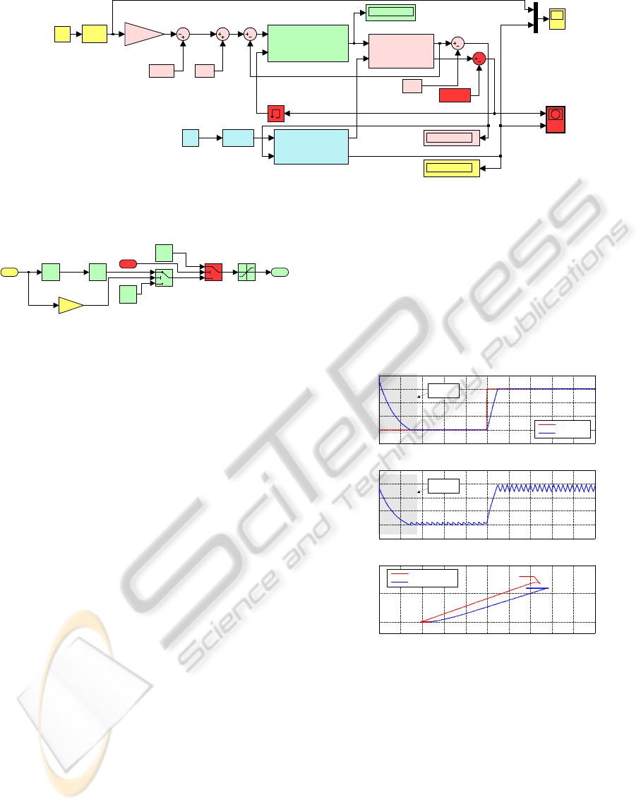
Introducing the controller in a general block
schema, with the non-linear SMA model, the
Simulink model in Fig. 8 was obtained for the SMA
actuators control (see Fig. 3). The input variable of
the schema is the desired skin deflection and the
output is the real skin deflection.
The “Integrated controller” block contains the
implementation of the law described by equation
(20) and of the preliminary observations related to
the SMA actuators physical limitations in terms of
temperature and supplying currents. Its schema is
shown in Fig. 9. The inputs of the block are the
control error (difference between the desired and the
obtained displacements) and the wires temperature,
and the output is controlled electrical current applied
on the SMA actuators. There are two switches in the
schema; the first one chooses one of the two options
in the control law (20) and the second one switching
the electrical current value to 0A when the SMA
temperature value is over the imposed limit. Also, a
current saturation block is used to prevent the
current increase over the physical limit supported by
the actuation SMA wires.
ICINCO 2010 - 7th International Conference on Informatics in Control, Automation and Robotics
10
Temperature
[K]
skin deflection [mm]
skin
deflection
[mm]
desired deflection [mm]
SMA elongation
[m]
skin
deflection
[mm]
0
skin deflexion [mm]
1
14.5
desired
skin deflection
[mm]
3/1000
cam factor
mm to m
XY Graph
Scope
0.078
SMA max set
[m]
0
SMA elongation [m]
Current
Force
Displacement
Temperature
SMA Model
1.8
SMA Initial
length [m]
1.8
SMA Initial
length
Diff error
Temperature
Current out
Integrated controller
Memory
F aero [N]
x [m]
F SMA [N]
y [mm]
Mechanical system
0
Current [A]
273.15
Celsius to Kelvin
1500
Aerodynamic
force [N]
Figure 8: The simulation model for the controlled SMA actuator with non-linear model.
1
Current out
Temperature
limiter
Switch
-1
Gain
0
Current when
cooling
Current
saturation
0
Current when
reached limit
PI
Controller
|u|
Abs
2
Temperature
1
Diff error
Current
Current
Figure 9: “Integrated controller” block in Simulink.
Loading the simulated model with aerodynamic
force F
aero
= 1500N, the characteristics in Fig. 10 are
obtained for a 6 mm step desired skin deflection (δ
v
).
First of all, can be observed that the controller work
good, the transition to the desired steady-state being
significantly improved through the integration of the
two control law in the equation (20): 1) the
amplitudes of oscillations were reduced and the
observed oscillations in the SMA temperatures
around the steady-state are due only to the thermal
inertia of the smart material; 2) the values of the
transition time from 0mm to the steady-state values
decrease from 20÷25 to approximate 5 s.
4 CONCLUSIONS
The objective of here presented research work is to
develop an actuation control concept for a new mor-
phing mechanism using smart materials, like Shape
Memory Alloy (SMA), as actuators. These smart
actuators modify the upper surface of a wing made
of a flexible skin so the laminar to turbulent
transition point moves close to the wing airfoil
trailing edge.
The designed controller must controls the SMA
actuators in terms of supply electrical current so that
to cancel the deviation between the required values
for vertical displacements (corresponding to the
optimized airfoils) and the real values, obtained
from position transducers. The envelope of the SMA
actuator in Fig. 5, obtained through numerical
simulation using model in Fig. 4 for different
aerodynamic load cases, confirms that the length of
the SMA wires is a complex function of the SMA
load force and temperature, the last one being
influenced by the supplying current in time and by
the interaction of the wires with the environment in
theirs cooling phase (when the electrical supply is
removed).
0 102030405060708090100
-2
0
2
4
6
8
0
20
40
60
80
100
120
0
5
10
10 20 30 40 50 60 70 80 90 100
20 30 40 50 60 70 80 90 100 110 120
Time [s]
Time [s]
Temperature [
o
C]
Temperature [
o
C] Displacement
v
[mm]Displacement
v
[mm]
v
required
v
obtained
SMA
initialisation
SMA initialisation
SMA actuation
SMA
initialisation
Figure 10: Response for a step input and F
aero
=1500 N.
As can be observed from Fig. 5, to obtain a skin
maximum vertical displacement (8 mm) in absence
of aerodynamic force, it is required a high
temperature (approximately 162˚C) in order to
counteract the spring force. Because the ability of
the SMA wires to contract is dependent upon Joule
heating to produce the transformation temperature
required, the need in higher temperature is reflected
by a need in higher electrical current. Due to the fact
that the aerodynamic forces reduce the actuators
load the required current and temperature values are
A MORPHING WING USED SHAPE MEMORY ALLOY ACTUATORS NEW CONTROL TECHNIQUE WITH
BI-POSITIONAL AND PI LAWS OPTIMUM COMBINATION - Part 1: Design Phase
11

decreased; i.e. for F
aero
= 1800 N the need in
temperature for the maximum vertical displacement
obtaining is approximately 90˚C.
The final configuration of the integrated
controller was a combination of a bi-positional
controller (particularly an on-off one) and a PI
(proportional-integral) controller, due to the two
phases (heating and cooling) of the SMA wires
interconnection. The resulted controller must behave
like a switch between cooling phase and heating
phase, situations where the output current is 0 A, or
is controlled by a law of PI type.
Using an integral criterion, the error minimum
surface criterion (Ziegler-Nichols), the PI controller
for the heating phase was optimal tuned, the resulted
values are K
P
=1792.8 and K
I
=787.0061. Evaluating
the systems’ performances one observed that the
poles of closed loop transfer function of the
controlled heating phase resulted with the values
(14) are all placed in the left-hand side of the s-
plane, so the obtained system is stable. On the other
way, the system was found to be completely
controllable and observable based on the values
established in equations (17)÷(19). So, the final form
of the integrated controller law was (20).
Loading the numerically simulated general
model (the non-linear one with F
pretension
=1500N) in
Fig. 8 with aerodynamic force F
aero
= 1500N, the
obtained characteristics in Fig. 10 confirm that the
controller works good, the transition to the desired
steady-state being significantly improved through
the integration of the two control law in the equation
(20): 1) the amplitudes of oscillations were reduced
and the observed oscillations in the SMA
temperatures around the steady-state are due only to
the thermal inertia of the smart material; 2) the
values of the transition time from 0mm to the
steady-state values decrease from 20÷25 to
approximate 5 s.
As second and third validation methods a bench
test and a wind tunnel test were performed and will
be presented in the second part of the paper, related
to the experimental validation.
ACKNOWLEDGEMENTS
We would like to thank the Consortium of Research
in the Aerospatial Industry in Quebec (CRIAQ),
Thales Avionics, Bombardier Aerospace, and the
National Sciences and Engineering Research
Council (NSERC) for the support that made this
research possible. We would also like to thank
George Henri Simon for initiating the CRIAQ 7.1
project and Philippe Molaret from Thales Avionics
and Eric Laurendeau from Bombardier Aeronautics
for their collaboration on this work.
REFERENCES
Chang, P., Shah, A., Singhee, M., 2009, Parameterization
of the Geometry of a Blended Wing Body Morphing
Wing, Project report, Georgia Institute of Technology,
April 2009, Atlanta, Georgia, USA
Georges, T., Brailovski, V., Morellon, E., Coutu, D.,
Terriault, P., 2009, Design of Shape Memory Alloy
Actuators for Morphing Laminar Wing With Flexible
Extrados, Journal of Mechanical Design, Vol. 31, Nº 9
Gonzalez, L., 2005, Morphing Wing Using Shape Memory
Alloy: a concept proposal, Final research paper, Texas
A&M University, College Station, Texas, USA
Grigorie, T. L., Botez, R. M., 2009, Adaptive neuro-fuzzy
inference system-based controllers for smart material
actuator modeling, Journal of Aerospace Engineering,
Vol. 223, No. 6, pp. 655-668
Hinshaw, T. L., 2009, Analysis and Design of a Morphing
Wing Tip using Multicellular Flexible Matrix
Composite Adaptive Skins, Master of Science Thesis,
Virginia Polytechnic Institute and State University,
Virginia, USA
Khalid, M., Jones, D. J., 1993, Navier Stokes Investigation
of Blunt Trailing Edge Airfoils using O-Grids, AIAA
Journal of Aircraft, vol.30, no.5, pp. 797-800
Khalid, M., Jones, D. J., 1993, A CFD Investigation of the
Blunt Trailing Edge Airfoils in Transonic Flow,
Inaugural Conference of the CFD Society of Canada.
Majji, M., Rediniotis, O. K., Junkins, J.L., 2007, Design of
a Morphing Wing: Modeling and Experiments, AIAA
Atmospheric Flight Mechanics Conference and
Exhibit, Hilton Head, South Carolina, USA
Mihoc, D., 1980, Teoria si elementele sitemelor de reglare
automata. Editura Didactica si Pedagogica, Bucuresti
Namgoong, H., Crossley, W. A., Lyrintzis, A. S., 2006,
Aerodynamic Optimization of a Morphing Airfoil
Using Energy as an Objective, 44th AIAA Aerospace
Sciences Meeting and Exhibit, Reno, Nevada, USA
Popov, A. V., Labib, M., Fays, J., Botez, R. M., 2008,
Closed-Loop Control Simulations on a Morphing
Wing, Journal of Aircraft, Vol. 45, pp. 1794-1803
Ruotsalainen, P., et. al., 2009, Shape Control of a FRP
Airfoil Structure Using SMA-Actuators and Optical
Fiber Sensors. Journal of Solid State Phenomena,
Volume 144, pp. 196-201
Smith, K., Butt, J., Spakovsky, M. R., Moorhouse, D.,
2007, A Study of the Benefits of Using Morphing Wing
Technology in Fighter Aircraft Systems, 39th AIAA
Thermophysics Conference, Miami, Forida, USA
Terriault, P., Viens, F., Brailovski, V., 2006, Non-
isothermal Finite Element Modeling of a Shape
Memory Alloy Actuator Using ANSYS, Computational
Materials Science, Vol. 36, No. 4, pp. 397-410
ICINCO 2010 - 7th International Conference on Informatics in Control, Automation and Robotics
12
