
AUTOMATED THREAT IDENTIFICATION FOR UML
George Yee, Xingli Xie and Shikharesh Majumdar
Dept. of Systems and Computer Engineering, Carleton University, Colonel By Drive, Ottawa, Canada
Keywords: Software threat identification, Software threat modeling, UML, expert systems, Secure software
development.
Abstract: In tandem with the growing important roles of software in modern society is the increasing number of
threats to software. Building software systems that are resistant to these threats is one of the greatest
challenges in information technology. Threat identification methods for secure software development can be
found in the literature. However, none of these methods has involved automatic threat identification based
on analyzing UML models. Such an automated approach should offer benefits in terms of speed and
accuracy when compared to manual methods, and at the same time be widely applicable due to the ubiquity
of UML. This paper addresses this shortcoming by proposing an automated threat identification method
based on parsing UML diagrams.
1 INTRODUCTION
Today, software systems are involved in almost
every aspect of our lives. From electrical power
generation, to telecommunications, to air travel,
software is essential. Unfortunately, software is
threatened by security problems that are getting
worst by the day. Building software systems that are
resistant to the growing number of threats against
them is one of the greatest challenges in information
technology (Yee, 2006).
Threat identification or threat modeling
methodologies have been proposed by researchers
for the development of secure software. Among
them are: Secure System Engineering Methodology
(Salter et al., 1998), threat modeling methodologies
based on Data Flow Diagrams (Howard & Lipner,
2006; Swiderski & Snyder, 2004; Saitta et al., 2005;
Microsoft, n.d.-A), Microsoft’s Threat Analysis and
Modeling (TAM) methodology (Ingalsbe et al.,
2008; Microsoft, n.d.-B), quantification on risk
analysis in threat modeling (PTA Technologies, n.d.;
Howard & LeBlanc, 2003), and expressing threat
scenarios in UML diagrams (Wang et al., 2007;
Object Management Group, n.d.-A).
Automated tools for threat modeling have also
been developed for the threat modeling
methodologies mentioned above. For example, a
tool for threat modeling by Microsoft automates the
threat modeling methodology by Swiderski &
Snyder (2004). This tool provides a user interface to
collect background information required for threat
modeling and generates the threat model by
modeling the software in data flow diagrams.
Another automated tool supports the TAM approach,
developed by the Microsoft Application and
Consulting Engineering team (Ingalsbe et al., 2008;
Microsoft, n.d.-B). This tool defines application
architecture in a set of components, service roles and
calls.
Current threat identification methodologies,
such as those mentioned above, exhibit two gaps.
One gap is that none of the methodologies has
proposed a threat identification process based on
analyzing UML models. The other gap is that there
is no automated threat identification method based
on parsing UML diagrams. Existing approaches of
software threat modeling rely on the developers to
draw Data Flow Diagrams, attack graphs or other
forms to express the architectural and data flow
information of the system. The use of UML for
analyzing threats and risks to a system is preferred
since i) UML is a widely used modeling language in
software engineering, and ii) software developers
who are modeling the system in UML may not be
familiar with attack graphs, or other forms that are
used in the security domain.
This paper describes preliminary research that
aims to fill the two gaps stated above. It looks at
deriving threats based on analyzing existing UML
diagrams, and shows how to automatically generate
threats to the software by using an expert system in
521
Yee G., Xie X. and Majumdar S. (2010).
AUTOMATED THREAT IDENTIFICATION FOR UML.
In Proceedings of the International Conference on Security and Cryptography, pages 521-527
DOI: 10.5220/0002996005210527
Copyright
c
SciTePress

conjunction with threat information from the UML.
Thus, this work aims to combine the benefits of
automation (speed and accuracy) with the ubiquity
of UML.
The objectives of this paper are to a) propose an
automated threat identification method based on
analyzing existing UML diagrams, and b) apply the
method to the UML model of an example web
service. This paper is organized as follows. Section
2 presents our approach for automated threat
identification. Section 3 implements the approach on
example UML diagrams. Section 4 discusses some
issues, and Section 5 presents conclusions and plans
for future research.
2 PROPOSED APPROACH
The proposed threat identification approach consists
of two phases, namely i) gathering relevant system
information, and ii) processing the UML diagrams to
identify threats. These phases are described as
follows.
Phase 1: Gather Relevant System Information
Identifying threats to a software system requires
certain information regarding the system’s design
and deployment. This information can be
categorized as a) assets that should be protected, b)
software dependencies, and c) security assumptions.
Assets are resources that the system must
protect from incorrect or unauthorized use
(Swiderski & Snyder, 2004). For example, the
common assets we are familiar with are business
equipment in an office that should not be stolen by
thieves, and sensitive data for a business that should
not be disclosed to its competitors. Physical assets
are easier to identify than abstract assets, such as the
company’s reputation. Different assets usually
require different forms of protection. For example,
money should not be lost or stolen, price data should
not be modifiable by an adversary, and a web service
should be available at all hours.
Software usually has dependencies. It runs on
operating systems and hardware. It might use
databases, a web server, or a framework (e.g. .NET
framework). Such dependencies are important for
determining the existence of threats.
Security assumptions specify the features of the
system or its environment that must to be true for the
system to remain secure. Defining the security
assumptions is important for the proper
identification of threats. For example, suppose that
the system relies on the underlying operating system
to protect encryption keys. A security assumption,
then, is that the operating system will protect the
keys (Howard & Lipner, 2006). For Microsoft
Windows XP, this assumption would be true if you
store the keys using the data protection API
(DPAPI). However, in the case of Linux (as of the
2.6 kernel), this assumption is incorrect, and leads to
new threats that put the keys at risk.
Phase 2: Process the UML and Identify the
Threats Using an Expert System
This phase is accomplished in 2 steps. In step 1, the
information needed to identify threats is extracted
from existing UML deployment and sequence
diagrams (available from normal UML-based
software development) in the form of Prolog facts.
In step 2, the threats are identified using an expert
system in conjunction with the facts from step 1.
Step 1 – Threat Information Extraction: The
extraction technique used here has been applied in
the literature for UML model checking and UML
quality assessment (Pap et al., 2001; Chimiak-Opoka
et al., 2008). Most UML modeling tools allow
machine processing of UML by expressing the UML
model in XML Metadata Interchange (XMI) form
(Object Management Group, n.d.-B). In our
approach we first export the UML model in XMI
format, in order to enable automatic machine
processing. The XMI file is then imported into a
logic programming language, e.g. SWI-Prolog with
its provided package, the SGML/XML parser (SWI-
Prolog, n.d.). The imported UML model (in XMI
form) is processed and the information needed, such
as the nodes, the instances, the interactive messages,
all their relations, and so on, is extracted in terms of
Prolog facts for the threat identification in step 2.
Step 2 - Threat Identification: The fact set
obtained from step 1, together with the relevant
system information gathered in Phase 1, form the
working data of our expert system for threat
identification. The associated knowledge base
contains a set of threat identification rules. The
inference engine is backward chaining (i.e. works
backwards from goals), as provided by SWI-Prolog.
This expert system analyzes the fact set and relevant
system information, and generates threats to the
software system based on the threat identification
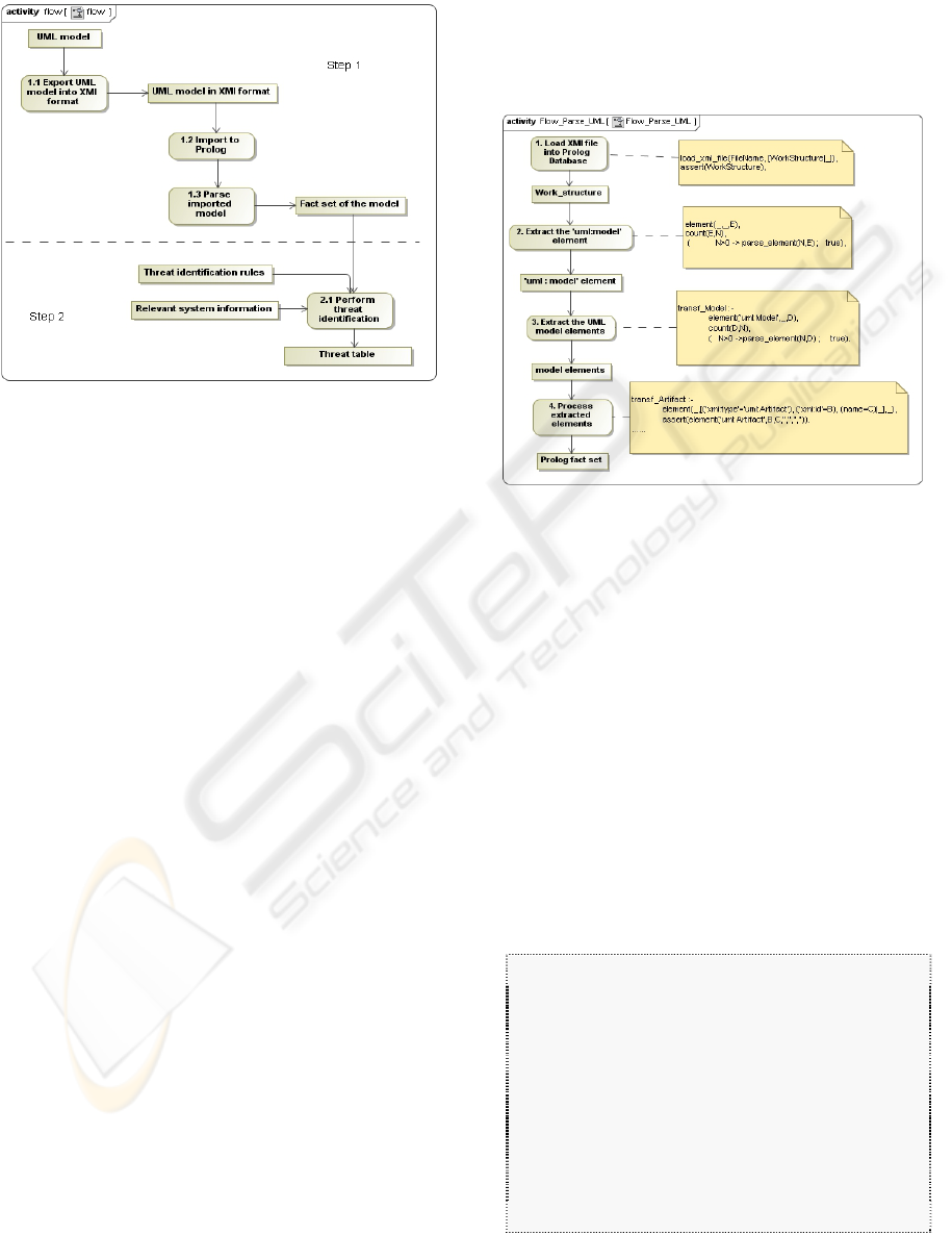
rules in the knowledge base. Figure 1 illustrates
Phase 2.
A knowledge base for an expert system is a
declarative representation of the expertise, usually in
the form of rules. These rules are often written in the
“IF THEN” format. A threat scenario explains how
the system can be compromised. The knowledge
SECRYPT 2010 - International Conference on Security and Cryptography
522
base is constructed by defining threat scenarios and
formulating them into rules.
Figure 1: Process flow of Phase 2.
3 PROTOTYPE
IMPLEMENTATION AND
DEMONSTRATION
We begin this Section with a prototype
implementation of our approach, using Prolog to
construct the expert system. The UML model was
obtained using the Magic Draw UML Modeling
Tool, version 16.0 (No Magic, n.d.) (note: in
practice, the UML model would already exist,
created as part of normal development); the expert
system was constructed using SWI-Prolog, version
5.6.63 by Jan Wielemaker (SWI-Prolog, n.d.). The
implementation consists of a user interface that
allows the user to interact with the expert system, a
procedure to process the UML model and extract the
Prolog fact set, a set of threat modeling rules
(knowledge base), and an analysis process that runs
the rules on the system information and outputs the
threats to the system. We used the SWI-Prolog built-
in backward chaining inference engine as our goal-
driven reasoning inference engine.
GUI User Interface: SWI-Prolog offers a user
interface package called XPCE (SWI-Prolog, n.d.).
This toolkit is object-oriented and offers different
user interface classes that can be easily instantiated
and organized into a recognizable and usable GUI.
Extracting Prolog Facts from UML: This
procedure will take a XMI file exported from the
UML model tool as input and extract the Prolog
facts. The processing flow and some sample code
are shown in Figure 2. In this Figure, the displayed
code processes the UML deployment and sequence
diagrams.
Rules for the Expert System: We investigated four
threat scenarios and formulated rules from them.
Figure 2: Processing flow for extracting Prolog facts from
the XMI form of the UML model.
The scenarios are: i) a Trojan horse threat scenario,
ii) a SQL threat scenario, iii) a Man-In-The-Middle
(MITM) threat scenario, and iv) a Denial of Service
(DoS) threat scenario. We could in principle have
more threat scenarios but four were deemed
sufficient to demonstrate our approach.
For example, consider the Trojan horse threat
scenario. Suppose in our UML model a message m
is sent to object obj. Message m contains sensitive
data that is not allowed to be modified-by or
disclosed to an adversary. Suppose there exists a
Trojan horse in our system. Then a threat exists,
namely that the sensitive data may be modified by or
disclosed to an adversary. The rule for this threat
scenario can be written in IF THEN format as
follows:
IF
object obj and
message m which has destination obj and
m contains sensitive data which should not be
modified by or disclosed to an adversary
and
there is a possibility that a Trojan horse is
installed in the system
THEN
threat exists for the sensitive data in m to be
modified by or disclosed to the
adversary
AUTOMATED THREAT IDENTIFICATION FOR UML
523
Threat Identification and Output of the Results
After all the facts are extracted and processed from
the XMI and saved, the inference engine performs
the threat identification by backward chaining
reasoning, based on the rules, the facts we have from
the XMI (UML model), and the relevant system
information. The threat identification is executed
with the following query:
findall([Location, Asset, Required_Protection,
Threat, Memo], threat(Location, Asset,
Required_Protection, Threat, Memo), A).
This query will identify all the threats along with
their locations, as determined by the rule set, and
produce a threat table in Microsoft Excel format
(using the SWI2EXCEL module (SWI-Prolog,
n.d.)). The threat table is further described below.
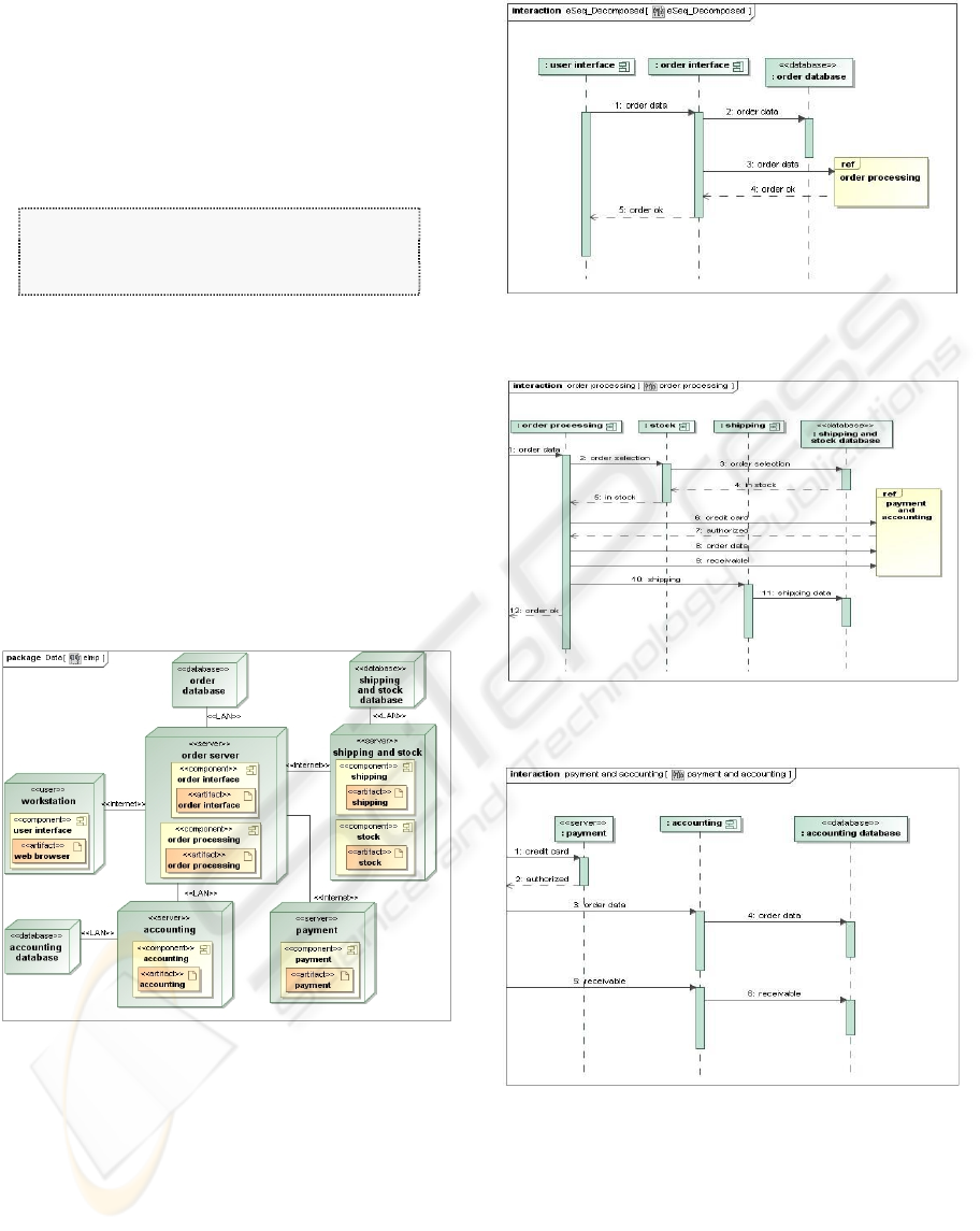
Next, we demonstrate our prototype by applying
it to the pre-existing UML model of a web store
service (Figures 3 and 4) from Yee (2007). The
service is hosted on a server and makes use of two
other web services, an accounting service and an
online payment service. The sequence diagram
(shown as 3 component parts in Figure 4) depicts a
successful order placement.
Figure 3: Deployment diagram for the web store service.
Phase 1: Gather Relevant Information on the
Web Service
By examining the system architecture with the
development team, we collect the following
information for the purpose of threat identification:
1. We are to identify threats for a successful
order placement.
2. The assets associated with a successful order
placement are credit card number and total
Figure 4(a): Beginning component sequence diagram for
the web store service (successful order).
Figure 4(b): Middle component sequence diagram for the
web store service (successful order).
Figure 4(c): Last component sequence diagram for the
web store service (successful order).
payment. The credit card number should not
be disclosed to adversaries and the total
payment should not be modifiable by
adversaries.
3. Trojan horses may be present in the service
platform.
4. The order data is stored in the order database
and in the accounting database. The
SECRYPT 2010 - International Conference on Security and Cryptography
524
receivable is stored in the accounting
database.
5. We assume that the communication paths and
the databases are not protected.
6. The order data is composed of customer
name, credit card number, and total payment.
The receivable consists of order number and
total payment. The credit card information
includes the customer name and credit card
number.
We next code this information in the file
relevant_information.pl, which will be loaded when
running the expert system.
Phase 2: Process the UML and Identify Threats
Using an Expert System
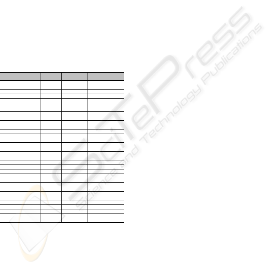
Steps 1 and 2 of Phase 2 (see Section 2) are
executed, identifying the threats shown in Table 1.
Table 1: Threat table, showing the threat identification
results from the demonstration.
Location Asse t
Required
Protection
Threat Mem o
627_1500 credit_card_number no_disclosure trojan_horse_attack
627_1500 total_payment no_modification trojan_horse_attack
664_1510 credit_card_number no_disclosure trojan_horse_attack
664_1510 total_payment no_modification trojan_horse_attack
799_1521 credit_card_number no_disclosure trojan_horse_attack
799_1521 total_payment no_modification trojan_horse_attack
6645_307 credit_card_number no_disclosure trojan_horse_attack
4234_325 credit_card_number no_disclosure trojan_horse_attack
4234_325 total_payment no_modification trojan_horse_attack
4558_343 total_payment no_modification trojan_horse_attack
8160_334 credit_card_number no_disclosure trojan_horse_attack
8160_334 total_payment no_modification trojan_horse_attack
9453_352 total_payment no_modification trojan_horse_attack
664_1510 credit_card_number no_disclosure sql_attack
order data stor ed in order database
664_1510 total_payment no_modification sql_attack
order data stor ed in order database
8160_334 credit_card_number no_disclosure sql_attack
order data stored in accounting database
9453_352 credit_card_number no_disclosure sql_attack
order data stored in accounting database
8160_334 total_payment no_modification sql_attack
order data stored in accounting database
9453_352 total_payment no_modification sql_attack
order data stored in accounting database
8160_334 total_payment no_modification sql_attack
receivable stored in accounting database
9453_352 total_payment no_modification sql_attack
receivable stored in accounting database
116_1087 credit_card_number no_disclosure MITM
Throug h message 4234_325
116_1087 total_payment no_modification MITM
Throug h message 4234_325
116_1087 total_payment no_modification MITM
Throug h message 4558_343
258_1013 credit_card_number no_disclosure MITM
Throug h message 664_1510
258_1013 total_payment no_modification MITM
Throug h message 664_1510
533_1053 credit_card_number no_disclosure MITM
Throug h message 8160_334
533_1053 total_payment no_modification MITM
Throug h message 8160_334
533_1053 total_payment no_modification MITM
Throug h message 9453_352
1657_990 availability DoS
763_1070 availability DoS
289_1104 availability DoS
Our prototype and demonstration give rise to the
following observations:
y UML model diagrams can be exported in XMI
format using the MagicDraw 16.0 UML modeling
tool and loaded into SWI-Prolog.
y XMI files exported by different UML modeling
tools are slightly different, which means that it
may be necessary to write different parsing code
for parsing XMI from different tools.
y Our automated approach appears to parse UML
fairly efficiently, but we did not do any
quantitative studies to confirm efficiency.
4 SOME PRACTICAL ISSUES
UML has been regarded as an informal or semi-
formal modeling language (Glinz, 2000). In
industrial settings, UML is widely used mainly
because it facilitates communication between
humans through visual means. When UML is used
for machine processing in automated processes (as
in this approach) some issues need to be considered,
as follows.
Missing Information
Certain details used in threat identification may not
be captured by UML, and thereby impact the results
of our approach. These include, for example, how a
system is protected for physical safety, what other
applications are running and the risks they pose, who
can access the system and how the system is
accessed. UML also lacks the ability to model
certain external entities and users that may be
critical to threat analysis, e.g. the role of an Internet
service provider. Some information may have been
omitted from the UML model of the system, either
because it was “too obvious” to be included in the
model or because it was considered only relevant to
security and not part of the UML model. One way to
solve this problem is to collect more detailed
relevant system information for the missing or
omitted information. Also the system model should
be more detailed in order to include enough
information for the automated threat identification.
Vague, Inconsistent, or Informal Information
The visualization capability and the informality of
UML provide more flexibility when modeling
software, but at the same time they cause problems
in automatic model processing. This is why UML is
often criticized for its vague semantics,
inconsistency and ambiguity. For example, in the
demonstration web store service, the message “order
data” can also be expressed as “order information”
and both terms sound the same to a human.
However, it is difficult for a machine to know that
they should be considered the same when it
processes the model automatically.
A realistic knowledge base can be developed by
a group of experts, as part of commercializing our
approach. However, building a knowledge base for
threat identification is still a huge task and the
following issues need to be considered.
AUTOMATED THREAT IDENTIFICATION FOR UML
525

Always Changing
The threat landscape is always changing, with new
vulnerabilities coming into play and existing
vulnerabilities subject to new kinds of threats. Thus,
it is difficult to build a complete set of rules for the
knowledge base. But one benefit is obvious - the
knowledge base can contain the threat identification
expertise of many experts, which can be
advantageous for development teams that lack this
expertise.
Need to Understand the Fact Set
The knowledge base relies heavily on understanding
the system model. The problems of vagueness or
missing information when modeling the system in
UML (as discussed above) may be solved either by
a) putting more detail in the UML to facilitate
construction of the knowledge base for threat
identification, or b) building a larger knowledge base
containing additional rules sufficient to understand
the problems caused by UML. In the latter case, the
knowledge base will not only contain the threat
identification rules, but also provide for reasoning
capability to cope with the deficiencies of UML
models.
5 CONCLUSIONS AND
FUTURE WORK
This work potentially fills the gap of a lack of threat
identification methodology based on analyzing UML
models, and the gap of a lack of automated
approaches for threat identification based on UML.
The limitations of this work include the issues
discussed in Section 4. Due to these issues, the
approach is probably best applied in conjunction
with other techniques such as manual code
inspection and designer testing, so that the different
techniques can support one another in terms of the
threats found, providing for more robust results.
Plans for future research include: a) addressing
the issues mentioned above, b) trialling the approach
with software developers, including using it in
conjunction with code inspection and designer
testing, c) investigating other UML diagrams and
elements for use in threat identification, and d)
performing a scalability analysis.
REFERENCES
Chimiak-Opoka, J., Felderer, M., Lenz, C., & Lange, C.
(2008). Querying UML Models using OCL and
Prolog: A Performance Study. 2008 IEEE
International Conference on Software Testing
Verification and Validation Workshop (ICSTW’08),
Lillehammer Norway, pp. 81-88, April.
Glinz, M. (2000). Problems and Deficiencies of UML as a
Requirements Specification Language. In Proceedings
of the 10th International Workshop on Software
Specification and Design (IWSSD-00), San Diego,
USA, pp. 11-22, November.
Howard, M. & LeBlanc, D. (2003). Writing Secure Code.
Microsoft Press, 2
nd
edition.
Howard, M. & Lipner, S. (2006). The Security
Development Lifecycle: SDL: A Process for
Developing Demonstrably More Secure Software.
Microsoft Press.
Ingalsbe, J.A., Kunimatsu, L., Baeten, T., & Mead, N.R.
(2008). Threat Modeling: Diving into the Deep End.
IEEE Computer Software, Volume 25, Issue 1, pp. 28-
34, January-February.
Microsoft (n.d.-A). Microsoft’s Threat Modeling Tool.
Available as of July 31, 2009 at:
http://www.microsoft.com/downloads/details.aspx?Fa
milyID=62830f95-0e61-4f87-88a6-e7c663444ac1&
displaylang=en.
Microsoft (n.d.-B). Microsoft Threat Analysis and
Modeling v2.1.2. Available as of July 31, 2009 at:
http://www.microsoft.com/downloads/details.aspx?Fa
milyId=59888078-9DAF-4E96-B7D1-
944703479451&displaylang=en
No Magic (n.d.). MagicDraw UML 16.0. Available as of
July 31, 2009 at: http://www.nomagic.com/
Object Management Group (n.d.-A). UML. Available as
of July 31, 2009 at: http://www.omg.org/
Object Management Group (n.d.-B). XMI. Available as of
July 31, 2009 at:
http://www.omg.org/technology/xml/index.htm.
Pap, Z., Majzik, I., & Pataricza, A. (2001). Checking
General Safety Criteria on UML Statecharts. In
Lecture Notes in Computer Science, Vol. 2187, pp. 46-
55, Springer-Verlag.
PTA Technologies (n.d.). Practical Threat Analysis.
Available as of July 31, 2009 at:
http://www.ptatechnologies.com/
Saitta, P., Larcom, B., & Eddington, M. (2005). Trike v.1
Methodology Document [Draft], July 13. Available as
of July 31, 2009 at:
http://www.octotrike.org/papers/Trike_v1_Methodolo
gy_Document-draft.pdf.
Salter, C., Saydjari, O.S., Schneier, B., Wallner, J. (1998).
Toward a Secure System Engineering Methodology.
In Proceedings of New Security Paradigms Workshop,
Charlottsville, VA, USA, pp. 2-10, September.
Swiderski, F. & Snyder, W. (2004). Threat modeling.
Microsoft Press.
SWI-Prolog (n.d.). SWI-Prolog. Available as of July 31,
2009 at: http://www.swi-prolog.org/
Wang, L., Wong, E., & Xu, D. (2007). A Threat Model
Driven Approach for Security Testing. In Proceedings
of the third IEEE Computer Society International
SECRYPT 2010 - International Conference on Security and Cryptography
526

Workshop on Software Engineering for Secure
Systems (SESS), Minneapolis, MN, USA, pp. 10-16,
May.
Yee, G. (2006). Recent research in secure software. NRC
Institute for Information Technology, National
Research Council Canada, NRCC# 48478, NPArC#
8914119, March. Available as of July 29, 2009 at:
http://nparc.cisti-icist.nrc-
cnrc.gc.ca/npsi/ctrl?action=shwart&index=an&req=89
14119&lang=en
Yee, G. (2007). Visual Analysis of Privacy Risks in Web
Services. In Proceedings of the IEEE International
Conference on Web Service 2007 (ICWS 2007), Salt
Lake City, UT, USA, pp. 671-678, July.
AUTOMATED THREAT IDENTIFICATION FOR UML
527
