
BASE STATION APPLICATION OPTIMIZER
Ronit Nossenson
RNWC, Katsanelson Street, Kfar-Sava, Israel
Keywords: LTE, Access network architecture, Backhaul bottleneck.
Abstract: Expectation and requirements for future wireless communication systems continue to grow and evolve.
Long-Term Evolution (LTE) is a recent effort taken by cellular providers and equipment vendors to step
into wireless broadband market. The key enhancements target an introduction of new all-IP architecture,
enhanced link layer and radio access. In LTE, one of the recurring problems is the bottlenecked backhaul
links, connecting the cell sites with the core network. The basic idea behind the Base Station Application
Optimizer is to replace the traditional base station with a smart entity, capable of analyzing and optimizing
the user data in the application level. In particular, such unit can prevent unnecessary data from travelling
though the bottlenecked backhaul network. The benefits of such entity are reduced latency, jitter and
network deployment costs.
1 INTRODUCTION
Cellular operators are competing traditional
broadband operators by offering mobile broadband
access and IP services such as rich multimedia (e.g.,
video-on-demand, music download, video sharing)
to laptops, PDAs, smart-phones and other advanced
handsets. They offer these services through access
networks such as High-Speed Packet Access
(HSPA), Evolution-Data Optimized (EV-DO) and,
in the near future, Long-Term Evolution (LTE).
These access networks promise to deliver
performance comparable to today’s ADSL services,
but with the added benefit of mobility and
ubiquitous coverage. The new technologies offer
mobile operators significantly improved data speeds,
short latency and increased capacity.
Traditionally, most of the backhaul lines,
connecting the cell sites with the core network, use
TDM (E1, T1) lines, each providing up to 2 Mbps
capacity. Though acceptable for voice and low data
rate applications, E1 capacity is inadequate for
higher data rates. Obviously, the direct result of the
backhaul bottleneck is low utilization of the radio
channels and an unsatisfying user experience.
Enormous backhaul upgrade is required to new
technologies such as Microwave, Metro Ethernet,
cable, or xDSL to satisfy the high bandwidth
demand. This upgrade is expected to be extremely
expensive and its cost casts a real doubt on the
profitability of enhanced network deployment. As a
result, the operators are seeking data reduction
solutions integrated with their network upgrades.
The biggest cost challenge facing wireless service
providers today is the backhaul network (Donegan,
2006).
The basic idea behind the suggested Base Station
Application Optimizer (BS-OPT, for short) is to
replace the traditional Base Station entity with a fast
and smart entity, capable of analyzing and
optimizing the user data in the application level. In
particular, such unit can use its location in the
operator network to prevent unnecessary data from
travelling though the backhaul and core networks.
Note that the suggested optimization is discussed
here in the context of the base stations of LTE
networks ("eNode-B") but it can be performed on
any base station or access point (e.g., IEEE 802.16,
IEEE 802.11).
2 LTE ARCHITECTURE
LTE is the next major step in mobile radio
communications, and is introduced in 3rd
Generation Partnership Project (3GPP) Release 8.
LTE uses Orthogonal Frequency Division
Multiplexing (OFDM) as its radio access
technology, together with advanced antenna
technologies.
119
Nossenson R. (2010).
BASE STATION APPLICATION OPTIMIZER.
In Proceedings of the International Conference on Data Communication Networking and Optical Communication Systems, pages 119-124
DOI: 10.5220/0003022601190124
Copyright
c
SciTePress
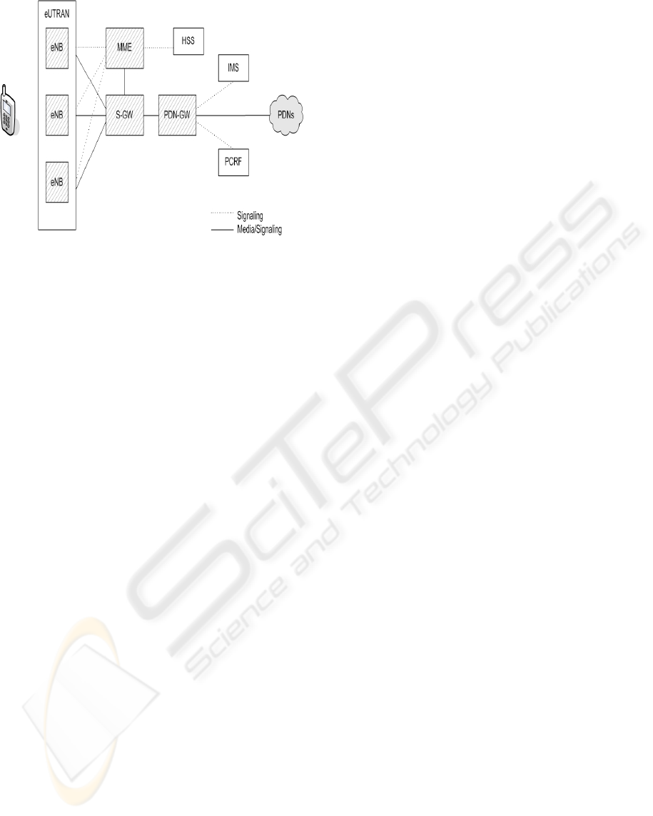
Figure 1: LTE/SAE High-Level Network Architecture.
When the evolution of the radio interface started, it
soon became clear that the system architecture
would also need to be evolved. Therefore, in
addition to LTE, 3GPP is also defining IP-based, flat
network architecture: System Architecture Evolution
(SAE) as presented in Figure 1. The LTE–SAE
architecture and concepts have been designed for
efficient support of mass-market usage of any IP-
based service. The architecture is based on an
evolution of the existing GSM/WCDMA core
network, with simplified operations. In the User
Plane (UP), for instance, there are only two types of
nodes (Base Stations and Gateways); while in
current hierarchical networks there are four types
(Node B, RNC, SGSN, GGSN). The gateway
consists of two logical UP entities, Serving Gateway
(S-GW) and Packet Data Network Gateway (PDN-
GW). Flat architecture with less involved nodes
reduces latencies and improves performance.
Another simplification is the separation of the
Control Plane (CP), with a separate Mobility-
Management Element (MME). A key difference
from current networks is that it is defined to support
packet-switched traffic only.
The only node in the Evolved Universal
Terrestrial Radio Access (eUTRAN) is the eUTRAN
Node-B (eNode-B, eNB in Figure 1). It is a radio
base station that is in control of all radio related
functions in the fixed part of the system. Typically,
the eNode-Bs are distributed throughout the
networks' coverage area, each residing near the
actual radio antennas. The interface between the
eNode-B and the gateways is the S1-U; the interface
between the eNode-B and the MME is the S1-C. The
interface between peers eNode-Bs is the X2. The
backhaul links are implementation of these three
interfaces and any required aggregation.
A noteworthy fact is that most of the typical
protocols implemented in today's Radio Network
Controller (RNC) are moved to the eNode-B. The
eNode-B is also responsible for header compression,
ciphering and reliable delivery of packets. On the
control plane, functions such as admission control
and radio resource management are also
incorporated into the eNodeB. Benefits of the RNC
and Node-B merger include reduced latency with
fewer hops in the media path, and distribution of the
RNC processing load.
The Policy and Charging Resource Function
(PCRF) is the network element that is responsible
for Policy and Charging Control (PCC). It makes
decisions on how to handle the services in terms of
QoS, and provides information to the PDN-GW, and
if applicable also to the S-GW, so that appropriate
bearers and policing can be set up.
The Home Subscription Server (HSS) is the
subscription data repository for all permanent user
data. It also records the location of the user in the
level of visited network control node, such as MME.
The IP Multimedia Sub-system (IMS) is service
machinery that the operator may use to provide
services using the Session Initiation Protocol (SIP).
For additional information on LTE network see
(Holma and Toskala, 2009, Dahlman et al. 2007).
3 BASE STATION APPLICATION
OPTIMIZER
We suggest a simple solution to the backhaul
bottleneck problem. The traffic load on the backhaul
links can be reduced by replacing the traditional
Base Station entity with the BS-OPT, a smart entity
capable of analyzing and optimizing the user data in
the application level. This section describes the
suggested solution architecture, support for user
mobility and finally discusses possible benefits and
limitations.
3.1 Architecture for the Base Station
Application Optimizer
Two options are considered for the new BS-OPT
architecture as described in Figure 2. In the first
architecture the BS-OPT is a stand-alone entity, not
integrated inside the base station, probing and then
analyzing and manipulating the traffic. The second
architecture is an integrated unit inside the base
station. Pros and cons of each solution are discussed
below.
DCNET 2010 - International Conference on Data Communication Networking
120
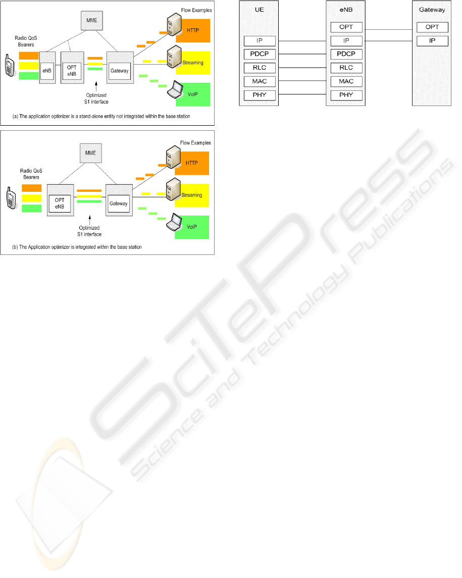
Figure 2: Data flow with the Base Station Application
Optimizer.
The stand alone architecture is described in
Figure 2A. The solution in this case is a separate
hardware and software package. It is located after
the base station ("bump in the wired") and is capable
to probe its entire traffic with very low delays. Note
that for each base station we should associate its
corresponding optimizer.
The benefit of this structure is mainly the
reduced dependence on the base station evolution.
This allows a complete freedom in the solution life-
cycle. Additionally, it provides a flexible network
structure: the solution can be installed at part of the
operator network and not on the entire network.
However, stand alone architecture means that we
should face the challenge of very-fast probing,
analysis and manipulation of the traffic. In addition,
it means multiple installations which are very
expensive. Furthermore, the most critical drawback
of this architecture is difficulties in supporting user
mobility. To support user mobility a new interface
should be defined between peer optimizers which
result in higher system complexity and cost.
The solution in the case of integrated
architecture is a software package installed on the
base station as presented in Figure 2(b). This
architecture saves the probing time and allows an
elegant and simple application solution. User
mobility is supported easily using, for example, the
regular buffer forwarding procedure defined by the
Figure 3: Protocol Stack for the User Plane with BS-OPT
and gateway optimizer.
3GPP specifications (3GPP TS 36.300, 2009) for
LTE as described in Section 3.2 below. However,
the main disadvantage of this architecture is the
required collaboration with base station evolution.
To avoid the difficult multiple installations and
to obey the high-speed requirement we recommend
implementing this solution as integrated software
within a base station (Figure 2 (b)).
Regarding LTE networks, the suggested protocol
stack of eNode-B with application optimizer is
described in Figure 3. Additionally, we study the
potential benefits of applying supporting
optimization algorithms at the operator gateway. The
corresponding suggested protocol stack of the
gateway is presented in Figure 3 too.
3.2 User Mobility Support
The LTE handover procedure is described in Figure
4. Using the integrated architecture of the BS-OPT,
user mobility can be supported as follows. At step 8,
the source eNode-B performs buffer forwarding of
the user buffered packets to the target eNode-B. The
application optimization layer provides the user data
to the lower layers. Thus, all optimized user data
will be forwarded as usual.
Regarding the user data which is currently in the
optimization process, we have two options: either to
cancel the optimization process as a part of step 18
(release resources), or continue with the
optimization and buffer forwarding. The source
eNode-B continuing processing resources might
save more processing resources at the target eNode-
B. For example, if objects from a particular web
page are already stored in the source eNode-B cache,
it will be better to transfer them from the source
eNode-B to the target eNode-B and to avoid the
double page request from the server.
We believe that both options should be
implemented and the choice between them should be
made on-line dependent on the specific traffic
characterization.
BASE STATION APPLICATION OPTIMIZER
121
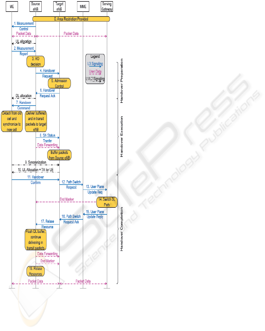
Figure 4: Message chart of the LTE handover procedure.
The control plane messages (solid and dot-dashed arrows)
and the flow of the user packets (dashed arrows) are
reported (3GPP TS 36.300, 2009).
3.3 Benefits and Limitations
The essential benefit of application layer
optimization in the base station (BS-OPT) is data
reduction at the backhaul bottleneck. This can help
in reducing the total backhaul upgrade costs and
improving the user experience by providing higher
actual data rates and shorter delays.
A major latency and data reduction can be
achieved by implementing an application cache at
the BT-OPT. Cache such as web cache, P2P or
streaming cache can reduce the traffic significantly
as a function of the cache size and the user
behaviour. Furthermore, researches have shown that
users do not tend to move a lot while consuming
data applications. In fact, according to (Halepovic
and Williamson 2005), users have high probability
(over 85%) to be connected to the same cell- the so-
called "home-cell". Obviously, such pattern of user
behaviour increases the cache hit rate dramatically.
Additional data reduction can be done by
replacing many live video streaming between each
user and an internet live video streaming server (see
Figure 5(a)) with a single live video stream between
the BS-OPT and the streaming server, and only then
delivering uni-streams to the specific users between
the BS-OPT and the users' in the cell (see Figure
5(b)). The BS-OPT should replace the Internet
Group Management Protocol (IGMP) role and
establish the users multicast group memberships.
The BS-OPT can control the transformation of the
single video stream into multiple uni-streams
according to the multicast group members list.
Meaning, it can hold a group table with all multicast
group members' details similar to IGMP.
Using location information, BT-OPT can help in
optimizing P2P traffic using algorithms similar to
P4P (Xie et al. 2008). The location information can
help optimizing the traffic path between peers and
reduce the file download latency while reducing
network resource consumption as demonstrated in
Figure 6B. However, implementing this feature
required capabilities of IP routing with mobile users
within the BT-OPT, such as suggested in Cellular IP
(Valko, 1999).
Additional data reduction and improvement in
the user experience can be achieved by fitting the
proper picture resolution/format, video format and
transfer rate to the handset capabilities and to the
available resources in the cell. Another example of
simple possible data reduction at the BT-OPT is file
compression. Many handsets do not support
compression formats. Once the User Agent (that is,
the browser application) of the handset reports that it
does not support compression formats, the web
servers avoid the file compression and response with
acceptable file format. The BT-OPT can overwrite
the relevant HTTP header to reflect compression
format support resulting in a compressed file
DCNET 2010 - International Conference on Data Communication Networking
122
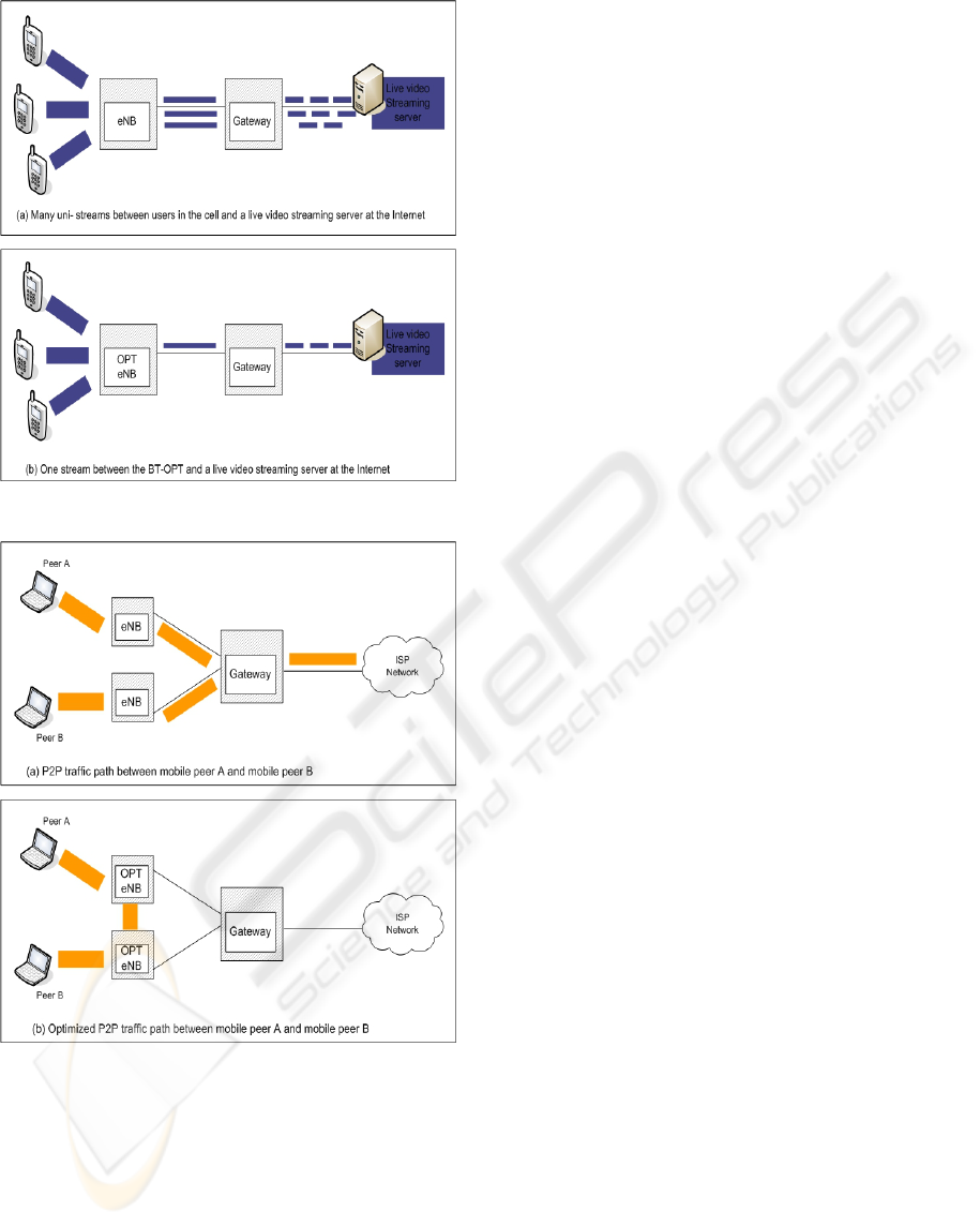
Figure 5: Using BT-OPT to optimize live video traffic.
Figure 6: Using BT-OPT to optimize P2P traffic.
transmission by the web server. The BT-OPT can
then decompress the files and transmit them to the
handset according to the original file format. A
supporting Central Optimization Entity at the
operator gateway can provide additional data
reduction such as compression of files that were not
compressed by the web servers or Delta compression
of any data traffic between the gateway and the BT-
OPT.
However, implementing Deep Packet Inspection
(DPI) technology in the base station is simple in
concept but complex in practice. Conceptually,
inspecting a packet to determine subscriber and
application type and then acting on that information
looks easy. However, traffic rates and rapidly
evolving applications add complexity. Based on
present data rates, packet rates are already
staggering. Each LTE user UL/DL channel can carry
millions of packets per second. At that speed, there’s
only ~100 nsec to receive and inspect each packet,
determine its application, perform the optimization
algorithms, modify it if necessary, and forward it to
the proper destination according to the optimization
plan. As a result, the base station must include
strong multi-core, multi-threaded processors for
packet inspection.
4 PERFORMANCE
EVALUATION
Performance of the BT-OPT is evaluated by
modifying the Qin-long et al. LTE/SAE model (Qiu
et al., 2009) for ns2 network simulator. Since we are
still working on the simulations, we can only discuss
preliminary results at this stage. The major
modifications (see Figure 7) of the network model
include extending the e-NodeB to support HTTP
caching, IP routing, and streaming multicasting
management. The data reduction on the backhaul
link is measured by comparing the sum of the
packets (uplink and downlink) on the queues
between the gateway and the OPT- eNodeB (S1
interface) with the sum of the packets on the queues
between the gateway and the traditional eNodeB,
under the same traffic generation. Other
performance parameters, such as average delay and
jitter are measured using the ns2 statistics.
Traffic scenarios include 5, 10 and 20 UEs with
different traffic QoS classes. Peer-to-peer traffic is
simulated by file download between peers UE in the
cell. Regarding the streaming traffic, we see that as
the number of users in the multicast group becomes
larger, the performance improves dramatically, as
expected. Regarding the web traffic, the
performance improvement highly depends on the
assumed cache hit rate. To improve our
understanding on the solution's limitation, currently
we are trying to evaluate the effect of the additional
processing time at the OPT-eNodeB on the
performance parameters.
BASE STATION APPLICATION OPTIMIZER
123
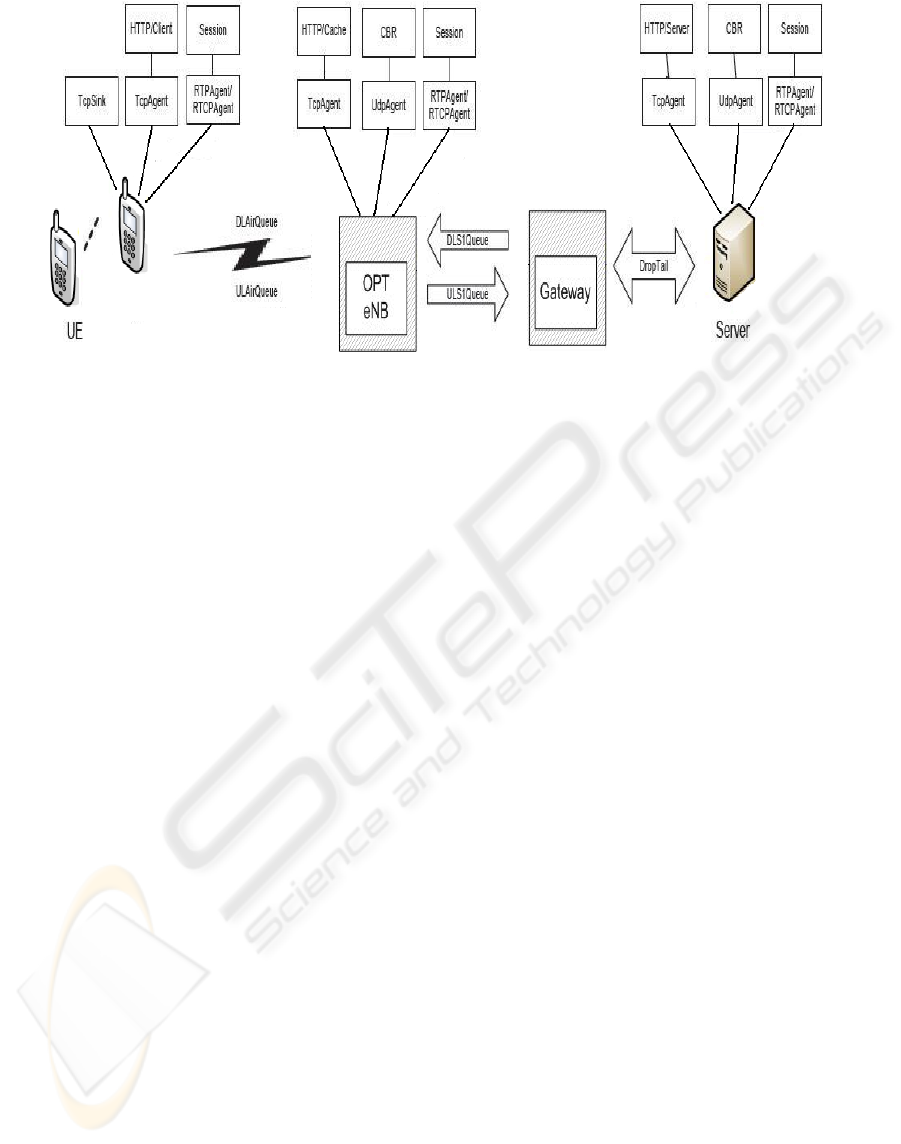
Figure 7: Simulation model.
5 CONCLUSIONS
In this paper we presented a novel solution to the
backhaul bottleneck problem of wireless broadband
networks: the Base Station Application Optimizer.
Benefits of the BS-OPT are reduced backhaul
upgrade costs and improved user experience by
providing higher actual data rates and shorter delays.
However, implementing fast Deep Packet Inspection
(DPI) technology in the base station is complicated
and requires careful design.
Future work includes additional simulations to
improve the evaluation of the system potential and
its limitations.
REFERENCES
3GPP TS 36.300, 3rd Generation Partnership Project;
Technical Specification Group Radio Access Network;
Evolved Universal Terrestrial Radio Access (E-
UTRA) and Evolved Universal Terrestrial Radio
Access Network (E-UTRAN); Overall description;
Stage 2 (Release 8), FRANCE, 2009-03.
Dahlman, E., Parkvall, S., Sköld, J., and Beming, P., 2007,
3G Evolution: HSPA and LTE for Mobile Broadband,
Elsevier, United Kingdom.
Donegan, P., 2006, Backhaul Strategies for Mobile
Carriers, In Heavy Reading , Vol. 4 No. 4,
http://www.heavyreading.com
Halepovic, E., and Williamson, C., 2005, Characterizing
and modeling user mobility in cellular data network,
Proceeding of the 2nd ACM international workshop
on Performance evaluation of wireless ad hoc, sensor,
and ubiquitous networks, Montreal, Quebec, Canada.
Holma, H., and Toskala, A., 2009, LTE for UMTS –
OFDMA and SC-FDMA Based Radio Access, John
Wiley & Sons Ltd, United Kingdom.
Qiu, Q., Chen, J., Ping, L., Zhang, Q., and Pan, X., 2009,
LTE/SAE Model and its Implementation in NS 2,
2009 Fifth International Conference on Mobile Ad-hoc
and Sensor Networks, Fujian, China, pp. 299-303.
Valkó, A. G. 1999. Cellular IP: a new approach to Internet
host mobility. SIGCOMM Comput. Commun. Rev.
29, 1 (Jan. 1999), pp. 50-65.
Xie, H., Yang, Y. R., Krishnamurthy, A., Liu, Y. G., and
Silberschatz, A, 2008, P4P: provider portal for
applications. SIGCOMM Comput. Commun. Rev. 38,
4 (Oct. 2008), pp. 351-362.
DCNET 2010 - International Conference on Data Communication Networking
124
