
EPC Virtual Lab: Experiments using an RFID
Location Simulator
Carlos Perdig
˜
ao
1,2
and Miguel L. Pardal
2
1
Link Consulting, Av. Duque de
´
Avila, 23, 1000-138 Lisboa, Portugal
2
Department of Computer Science and Engineering, Instituto Superior T
´
ecnico
Technical University of Lisbon, Av. Rovisco Pais 1, 1049-001 Lisboa, Portugal
Abstract. Radio frequency identification (RFID) is an automatic data capture
technology that has great potential to improve business. However, RFID projects
have significant up-front costs: buying tags and readers, and installing them in
business locations. Until now, a physical deployment was required to properly
test RFID software and its integration with existing systems.
This paper describes EPC Virtual Laboratory (EPC VLab), a physical world
simulation engine, that can be used to feed standard RFID information systems
with realistic data. The simulator has proved to be useful for preliminary and
exploratory testing.
1 Introduction
Radio frequency identification (RFID) is a technology that can be used to tag physical
goods, allowing them to be detected automatically. Readers communicate with tags
using a wireless power and data link [1].
The Electronic Product Code (EPC) framework [2] defines standards for a compre-
hensive supply chain management system based on RFID. It encompasses tags, readers,
data, and information systems.
The working principles of RFID imposes specific requirements and constraints on
software [3]. To properly assess them for a specific project, a pilot deployment, at least,
is required. This approach implies significant up-front costs: tags, readers, and their
proper installation in a business location. All these costs make RFID projects particu-
larly risky, and can steer many companies away for experimenting with the technology.
This paper proposes EPC Virtual Laboratory (EPC VLab), a physical world simu-
lation engine, that can be used to feed EPC information systems (EPCIS) with realistic
data and test their integration with Enterprise Resource Planning (ERP) systems.
The deliverable is the identification of data sources and flows i.e. the “questions”
that EPCIS and “ERP” should answer and what data is used to answer them.
2 EPC VLab
EPC VLab is a physical world simulator. Its main purpose is to allow the user to model
an RFID location with minimal effort.
PerdigÃ
ˇ
co C. and L. Pardal M.
EPC Virtual Lab: Experiments using an RFID Location Simulator.
DOI: 10.5220/0003027401080113
In Proceedings of the 4th International Workshop on RFID Technology - Concepts, Applications, Challenges (ICEIS 2010), page
ISBN: 978-989-8425-11-9
Copyright
c
2010 by SCITEPRESS – Science and Technology Publications, Lda. All rights reserved

In the following sections the logical and physical architectures of the simulator are
presented.
2.1 Logical Architecture
The logical architecture of the simulator describes the software layers and their respon-
sibilities. Each layer has its own set of possible actions and expected results, as depicted
in figure 1.
Fig. 1. EPC VLab Logical architecture.
Physical World. The user interacts mainly with the ‘Physical World’, by creating,
moving and deleting objects in a command console, shown in figure 2. The user gets
feedback from the console and also from a graphics area, where an world representation
is kept up-to-date.
Objects can be aggregated [4] for transport in boxes, pallets, etc.
RFID World. The ‘RFID World’ layer is where the user can create RFID readers and
tags. Each must be associated with an existing object. Moving the physical object moves
the RFID entity as well.
Information Systems. The ‘Information Systems’ layer is where the (simulated) world
is captured and given data representation. Here the user can query the EPCIS, and the
“ERP” stub to confirm the correct operation of the whole system.
2.2 Physical Architecture
Figure 3 presents an overview of the physical architecture.
The World Simulator module is the responsible for the interaction with the user by
executing the commands that control the objects.
Whenever the command received is related with readers or tags, the World Simula-
tor communicates with the Rifidi
3
Emulator. The Rifidi Emulator is then used to instan-
tiate each reader, and manage the detected tags.
3
http://ridifi.org
108
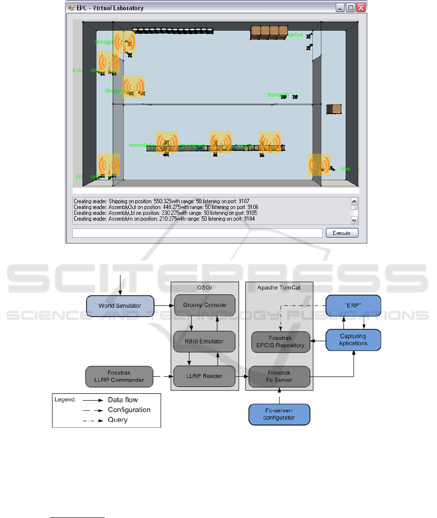
Fig. 2. VLab - Simulator User Interface.
Fig. 3. EPC VLab physical architecture.
The Fosstrak
4
fc-Server is then configured to periodically consume Application
Level Events (ALE) reports from each reader, and deliver them to Capture Applica-
tions. The Capture Applications communicate with the “ERP” and EPCIS to obtain
context to create a business event and inserted it in the EPCIS.
4
http://www.fosstrak.org/
109

The “ERP” stub is a Microsoft .Net
5
Web Service.
The Fosstrak LLRP Commander is used to configure each reader once it is deployed.
3 Case Study: Laptop Factory
The case study for the simulator was a laptop factory
6
. The laptop factory’s main acti-
vity is to assemble components from different parts of the world into a final product.
After the laptop is produced, it can be shipped to customers.
A factory’s RFID system should be able to track each object inside the factory area,
and benefit from automatic stock keeping, automated production and shipping control.
3.1 Modeling
The factory is divided in four areas: Entrance, Storage, Assembly Line, and Shipping.
In a normal operation, the components are accepted and checked in the Entrance. After
this initial step, all components are taken to the storage area until they are needed for the
assembly line. Each laptop is stored after production, until a shipping order is received.
The following table summarizes the areas where the business steps take place:
Entrance Storage Assembly Line Shipping
Unpack Storage Prepare components Pack
Check Pick Assemble Ship
- - Test -
- - Pack -
3.2 Implementation
Figure 4 is a graphical representation of the virtual factory, with all the readers identi-
fied.
The first chosen reader position was the organization border, the place where the
components enter (EntranceIn), and the exit where laptops leave (Shipping). After this
on the storage area we created two gates for components/laptops storage (StorageIn),
and another two gates for components/laptops picking (StorageOut). The remainder
readers cover specific points on the factory, such as the product checking entrance (En-
tranceOut), the entire assembly line (AssemblyIn/AssemblyLabel/AssemblyOut).
Each reader has an IP port in the range [9100,9200] and an associated capture appli-
cation (running at ports in range [9000,9100]). Finally we considered an EPCIS running
on endpoint: /factory-epcis/ and a simplified version of an “ERP”, that would return the
dynamic information of the results processed by the capture applications.
5
http://www.microsoft.com/NET/
6
The case is based on an actual product, but the factory is fictional.
110
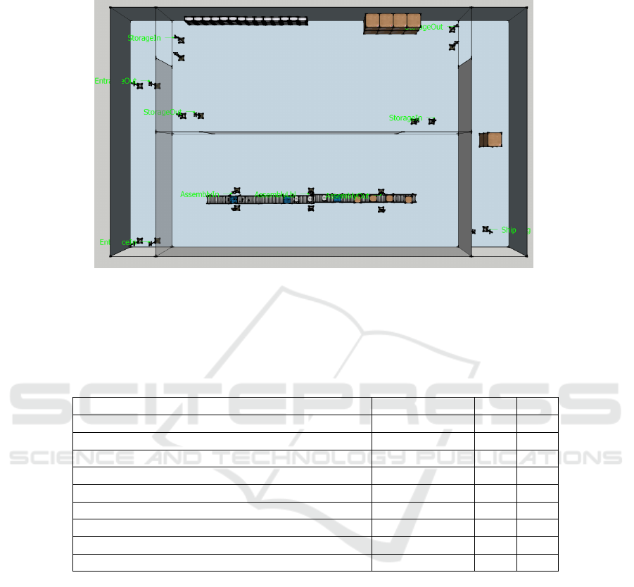
Fig. 4. Test Case - Factory Plant.
3.3 Findings
The following table summarizes the findings using simulations. It contains the business
questions that the laptop factory RFID system needs to answer, and which system holds
the data required for the answer: EPCIS or “ERP”.
Business Question Case requirement EPCIS “ERP”
When was the item produced? No Yes No
What is the bill-of-materials of the product? Yes Yes Yes
What is the history (trace) of detections ? Yes Yes No
By which partners did the item pass? Yes Yes No
How many modifications did the product suffer? No Yes No
What is the object state? Yes Yes No
Who modified the product? No Yes Yes
Was the object consumed or destroyed? No Yes No
What is the most likely future position of the object? No Yes Yes
4 Conclusions and Future Work
This paper described the implementation of EPC-VLab, an RFID location simulator,
capable of representing the physical world, and supplying tag read data to an EPC-
compliant information system. The simulator proved useful to analyze the “laptop fac-
tory case study”: system limitations, the position and range of readers, information
written on tags, and all the configurations needed to deploy the system.
The next stage in development is to simulate more than one location. The idea is
to ultimately represent a complete supply chain, and to identify requirements for a dis-
covery service, to support the creation of federations of business partners that share
111

business data. The simulation of errors in the multiple layers will be extended to fur-
ther explore RFID constraints. The validation of EPCIS and “ERP” systems will have
automatic assertions rather instead of manual inspections.
Acknowledgements
This work was supported by the rfrbNet project (Rede Federada de Rastreabilidade
de Bens) financed by the Portuguese Institute for Small and Medium Enterprises and
Innovation IAPMEI (nr. 5085).
Miguel L. Pardal is supported by a PhD fellowship from the Portuguese Foundation
for Science and Technology FCT (SFRH/BD/45289/2008).
References
1. K. Finkenzeller, RFID Handbook: Fundamentals and Applications in Contactless Smart Cards
and Identification, 2nd ed. John Wiley & Sons, Ltd, 2003.
2. K. Traub, F. Armenio, H. Barthel, L. Burstein, P. Dietrich, J. Duker, J. Garrett,
B. Hogan, O. Ryaboy, S. Sarma, J. Schmidt, K. Suen, and J. Williams, The
EPCglobal Architecture Framework 1.2, GS1 Std., 09 2007. [Online]. Available:
http://www.epcglobalinc.org/standards/architecture/
3. C. Floerkemeier, C. Roduner, and M. Lampe, “RFID application development with the
Accada middleware platform,” IEEE Systems Journal, Special Issue on RFID Technology,
12 2007. [Online]. Available: http://www.fosstrak.org/publ/FosstrakIEEESystems.pdf
4. BRIDGE, “Requirements document of serial level lookup service for various industries,” Uni-
versity of Cambridge and AT4 wireless and BT Research and SAP Research and ETH Zurich
and GS1 UK, Tech. Rep., 08 2007.
112
