
On the Use of UML Stereotypes in Creating
Higher-order Domain-specific Languages and Tools
Edgars Rencis* and Janis Barzdins
Institute of Mathematics and Computer Science, University of Latvia, Riga, Latvia
Abstract. Although many different approaches to building graphical domain-
specific languages and tools exist nowadays, no platform can ever be said to be
final from the usability point of view. In this paper, we show how we can inte-
grate UML stereotype-like mechanism into a tool-building framework in a very
user-friendly way. Having such a higher-order language, a user can create new
tools or adjust existing ones operating only with the concepts of the language
and knowing nothing about the technical details of the platform.
1 Introduction
In the field of domain-specific modeling, there has always been a question about how
to make a tool allowing one to develop domain-specific languages in a user-friendly
way. Much ongoing research exist towards this goal, as well as many commercial and
industrial domain-specific tool-building platforms are already developed (MetaCase
company and their tool MetaEdit+ [1] as well as Microsoft with their DSL Tools [2]
could be mentioned as two leaders in the field). However, the usability of a tool-
building platform can never be said to be final and perfect – there is always a place
for improvements.
In this paper, a slightly different method of creating new domain-specific lan-
guages and tools is presented. We try to focus on letting user to adjust a somehow-
made domain-specific language and tool to his/her own needs. At the same time, we
allow one to perform so called marginal adjustments meaning that a completely new
graphical tool can be built from scratch. Although from the user point of view the tool
would indeed be built “from scratch”, there is actually an additional knowledge about
the tool – its graphical nature – meaning it will allow one to introduce nodes and
edges in a diagram and to adorn them somehow. Thus, here, a phrase “from scratch”
actually means “from a graph drawing tool” (having concepts like a node, an edge, a
compartment, etc.).
The main ideas are outlined in the rest of the paper. Section 2 introduces the no-
tion of a higher-order domain-specific language, while section 3 shows how UML
stereotypes can be used to set the base for defining such a language. In section 4,
some technical background of our solution is provided. Some related work is in-
spected in section 5.
*
Partially supported by ESF project 2009/0138/1DP/1.1.2.1.2/09/IPIA/VIAA/004
Rencis E. and Barzdins J..
On the Use of UML Stereotypes in Creating Higher-order Domain-specific Languages and Tools.
DOI: 10.5220/0003561400140025
In Proceedings of the 3rd International Workshop on Model-Driven Architecture and Modeling-Driven Software Development (MDA & MDSD-2011),
pages 14-25
ISBN: 978-989-8425-59-1
Copyright
c
2011 SCITEPRESS (Science and Technology Publications, Lda.)

2 Higher-order Domain-specific Languages
The terminology here is taken from the world of model transformations. A transfor-
mation is said to be of higher order if it interferes somehow with other transforma-
tions, or in other words – if its input and/or output model is a transformation model
itself [3]. Higher Order Transformations or HOTs can thus be divided into three
groups regarding to their actions performed on other transformations:
1) the ones creating other transformations;
2) the ones analyzing other transformations;
3) the ones modifying other transformations.
Similarly, we can talk about domain-specific languages (DSL) designed for the sole
purpose of performing some actions (create, analyze, modify) on other domain-
specific languages. Also, the same would apply to domain-specific tools (DST) in
some way – a tool can also be used to create other tools or to analyze/modify beha-
vior of other tools.
There are several issues to be addressed while developing such a higher-order
domain-specific language. One of the most important aspects of such a DSL would be
its ability to not only let one to make some new languages from scratch, but also to be
able to perform some adjustments on already existing languages, so the “higher-
order” notation would not apply in one aspect only.
Other important issue is to let one to add some extra functionality to the DST by
programming it in some model transformation language. We like to stress the saying
that easy things (tools, functionality) must be achieved easily (i.e., by clicking mouse
buttons and entering some minor information) while hard things (more sophisticated
tools) must also be obtained somehow (i.e., by programming some extra functions).
While programming, one has to get through by dealing only with the new language
concepts introduced by the newly created DSL and knowing nothing about the real
technical metamodels of the platform really existing in the repository. These and
other issues are addressed in the further sections of this paper.
3 Using UML Stereotype-like Mechanism
The main idea of how to develop a higher order DSL and DST is to use the UML
stereotype mechanism [4] as a base concept to adjust the behavior of an existing DST.
With stereotypes, UML allows to change the appearance of graphical language sym-
bols and their text compartments as well as to add extra compartments as so called
stereotype attributes. In this paper, we try to go further and add some extra features
that can be configured using the stereotype-like mechanism. Using such advanced
stereotypes, quite a wide range of adjustments of a domain-specific language or tool
can be provided. Several types of adjustments being possible to make by the ad-
vanced stereotypes are specified in the next subsections. To demonstrate the mechan-
ism, we have integrated it into a graphical tool-building platform GRAF [5] which
uses the principles of the Transformation Driven Architecture (TDA, [6]). As an
example case study, a simple flowchart editor will be used in the following subsec-
tion.
15

3.1 Stereotype Base
Like in UML, a stereotype needs to have a base type on which it is to be defined.
Here, base types are concepts of the base domain-specific language which are about
to be adjusted. Since there can be different types of concepts (base types), there are
also different types of stereotypes:
1) stereotype on node – stereotype defined on a node-like graphical element (e.g., a
Class in a UML class diagram);
2) stereotype on edge – stereotype defined on an edge-like graphical element (e.g.,
an Association in a UML class diagram);
3) stereotype on port – stereotype defined on a small node-like graphical element
than can only be attached to a regular node and can’t exist for itself (e.g., a Pin in a
UML activity diagram);
4) stereotype on free box – stereotype defined on a region-like graphical element
used for visual purposes only and knowing nothing about other elements that happen
to be located in the same physical are in the diagram;
5) stereotype on free line – stereotype defined on a free line that does not have to
connect two particular graphical elements but is instead allowed to be situated any-
where in a diagram;
6) stereotype on compartment – stereotype defined on a text compartment of some
graphical element (e.g., an Attribute compartment in a UML class diagram).
As it can be suspected, these six types of stereotypes are derived from the types of
elements being possible to obtain using the abovementioned tool-building platform
GRAF. Of course, if we used a different platform using different MOF-like [7] graph-
ical element system, types of stereotypes would also be different. For instance, in
MetaEdit+, we would use the GOPPRR concepts and stereotypes would be defined
on Graph, Object, Property, Port, Relationship and Role. All the same, the language
and tool adjustment mechanism does not depend on the concrete stereotype types in
use.
From the end-user point of view, stereotypes are to be defined in a separate dia-
gram called the profile. If a tool is to be built “from scratch” (from the end user point
of view), that means the base tool for drawing graphs is already configured somehow
and put into the repository. That means we already have such element types as
“Node” and “Edge”. A flowchart editor (or any other tool) can now be made by creat-
ing stereotypes on these six base types. For instance, an “Action” in flowchart editor
would be made as a stereotype on base type “Node” while a “Flow” would be a ste-
reotype on base type “Edge”. The language of our advanced stereotypes consists of
the graphical notation for stereotypes together with some extra information to be
entered through a dialog window. A stereotype defining flowchart element “Action”
can be seen in Fig. 1.
3.2 Additional Compartments
UML provides a possibility to create additional text compartments for elements ha-
ving particular stereotypes. In UML version 1.5 they were so called tagged values
16
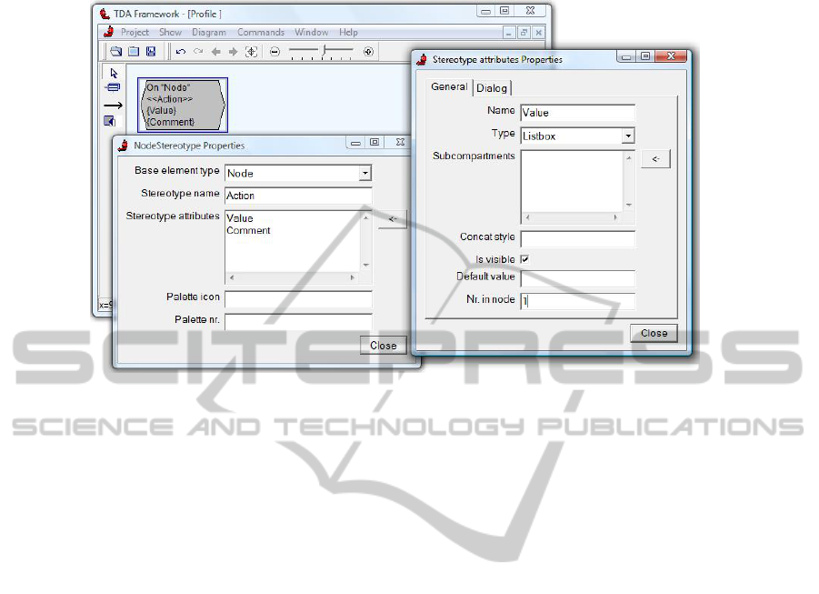
Fig. 1. Definition of “Action” – graphical notation + dialog windows.
which evolved in more natural stereotype attributes in UML 2.0. Using our advanced
stereotype mechanism, these additional attributes can be configured freely – just like
the original compartments created in the process of developing the base language. For
every stereotype attribute, several things can be specified:
1) attribute name;
2) attribute type in terms of how its value will be entered through the dialog window
– input field, multiline field, checkbox or collection meaning that the attribute will
consist of several sub-attributes which in their turn can be specified likewise;
3) location of the attribute in the visual element;
4) location of attribute value entering field in the dialog window;
5) attribute adornments – prefix and/or suffix to be added to the value of the attribute
when showing it in the visual element.
An example of how the addition of new compartments looks like from the end user
point of view is seen in Fig. 1 – flowchart element “Action” is supplemented by two
new compartments – “Value” and “Comment”.
3.3 Affecting Styles
A very important aspect in defining or adjusting a domain-specific language is the
specification of visual appearance of language elements. Using advanced stereotypes,
several types of visual style specification are allowed:
1) element style can depend on its stereotype – it works for all six previously men-
tioned stereotype types;
2) text compartment style can depend on stereotype applied to its containing element
(e.g., style of UML Class name changes to “Italic” if class stereotype is changed to
17

“Abstract class”);
3) sub-compartment style can depend on stereotype applied to its containing super-
compartment;
4) text compartment style can depend on stereotype applied to one of its sibling
compartments (the ones contained by the same parent element or compartment).
Several additional issues arise here regarding the specification of style for some par-
ticular element or compartment – it can depend on various (possibly contradictious)
statements. In that case, some priority of style assignments can be specified, e.g.,
compartment stereotype redefines the style for that particular compartment set by a
stereotype applied to the containing element which in its turn redefines the style set
by compartment’s sibling compartments. But again – several siblings can specify
different styles for the same compartment. Here, we declare that to be a bad design
pattern – the behavior of the tool is not specified in this case.
3.4 Other Features
Other features of the advanced stereotype mechanism include:
1) performing some minor actions with base compartments when applying a stereo-
type (e.g., specifying default values for some attributes, removing base attribute input
fields from dialog window etc.);
2) the notion of a profile – a named set of stereotypes than can be exported from one
tool and imported into another;
3) showing stereotypes in tool’s palette as separate palette elements or hiding them
from the palette;
4) showing or hiding base element types in tool’s palette when a profile is applied.
Other additional features can also be included here as needed.
3.5 Use Cases of the Advanced Stereotype Mechanism
Having a concrete domain-specific tool in hands, one can perform quite a wide range
of adjustments to it using the stereotype mechanism described briefly in this section.
On the other hand, it was said before that we want to use this approach also to make a
new tool as if from scratch. Since making a tool from scratch actually meant perform-
ing adjustments to a very general graph drawing tool (meaning someone has already
configured for us some basic element types like “Node” and “Edge” and some basic
compartment types like “Caption”), this advanced stereotype mechanism also allows
us to create a very wide range of graphical domain-specific tools. The only restric-
tions here are those put by the tool-building platform in use. Since we use the GRAF
platform, the only restrictions in our case are put on the types of elements from which
the abovementioned general graph drawing tool can consist – a node, an edge, a port,
a free box, a free line, and a compartment. The current version of the graph presenta-
tion engine of GRAF [5] allows us to use these six types of visual elements as well as
defines some relations between them (e.g., an edge always have a start element and an
end element, a node can be either contained in another node or stand alone, a port is
18

always attached to a node, etc.). Having such a graph drawing tool, one can easily
make a new tool as a profile of his/her own consisting of stereotypes defined on the
allowed base element types. Also, the base elements can be removed from the palette
and replaced by the new language concepts leaving the end user (the one using the
newly created tool) no visual resemblance to the real base tool being adjusted.
Although simple tools can easily be developed using this mechanism, we need to
allow one to define more sophisticated tools as well. While quite a wide class of tools
can be created using our advanced stereotypes, it is also clear that not everything can
be specified using stereotypes and some things need to be programmed in a model
transformation language and somehow added to the tool functionality. The ideas
about these issues are described in the next section.
4 Extending the Tool with Manually Written Function Calls
In order to explain a possibility to extend the higher-order DST with extra functions
properly, we must dig a little bit into the technical implementation of the Transforma-
tion Driven Architecture, the GRAF tool-building framework and the way advanced
stereotypes fit in.
4.1 Basic Principles of TDA
The Transformation-Driven Architecture is a metamodel-based approach for system
(in particular, tool) building, where the system metamodel consists of one or more
interface metamodels served by the corresponding engines (called, the interface en-
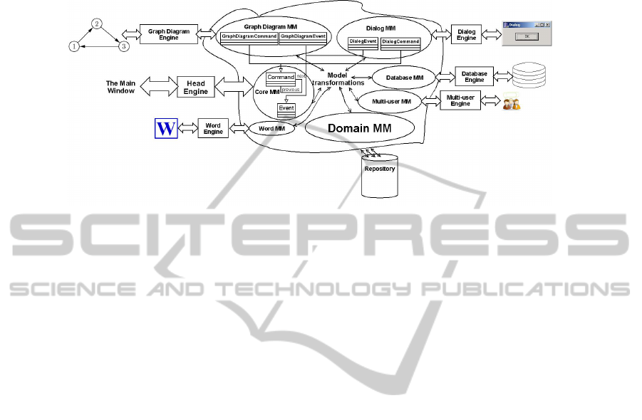
gines) and the (optional) Domain Metamodel [6]. There is also the Core Metamodel
(fixed) with the corresponding Head Engine managing the main application. Model
transformations are used to link instances of the mentioned metamodels together (see
Fig. 2).
The Head Engine is a special engine, whose role is to provide services for trans-
formations as well as for interface engines. For instance, when a user event (such as a
mouse click) occurs in some interface engine, the Head Engine may be asked to call
the corresponding transformation for handling this event. Also, a transformation may
give commands to interface engines. Thus, the Core Metamodel contains classes
Event and Command, and the Head Engine is used as an event/command manager
[6].
The main advantage of TDA lies in its extendability – anybody can take the core
of TDA and extend it with his or her own interface engines freely. Addition of new
engines is a very simple process in TDA if compared with other popular tool-building
frameworks. To add a new engine in TDA, you have to specify the interface metamo-
del for that engine. It can be a very simple one consisting of only one class and im-
plementing only one method for it – the method processing commands received from
transformations. If some more data are needed for the engine, the interface metamo-
del can contain more classes of course. On the other hand, to add a new plugin (an
engine analog) in Eclipse Modeling Framework [8], one has to perform a number of
19
actions. It requires a deep understanding of the Eclipse platform and a lot of technical
work.
Fig. 2. The Transformation-Driven Architecture with some interfaces.
4.2 Basic Facilities of GRAF Tool-Building Framework
GRAF is a MDE-based graphical domain- specific tool definition framework based
on principles of the Transformation-Driven Architecture [6]. GRAF is an evolution of
the earlier version of graphical tool-building platform called GrTP [9]. Besides the
TDA core, several interface engines have been implemented in GRAF. The most
important of them in the context of stereotypes is perhaps the Graph Diagram Engine
[10] mentioned in Fig. 2. The graphical primitives this engine can distinguish were
mentioned in section 3.1.
In short, the three main parts of GRAF are the following ones:
1) the Tool Definition Metamodel (TDMM) – every new tool will be an instance of
this metamodel;
2) the Universal Interpreter (UI) – a transformation interpreting the instance of
TDMM at runtime thus turning it into a working tool;
3) the Configurator – a graphical domain-specific language for creating new tools
within GRAF, that is, for creating proper instances of TDMM.
Knowing the TDMM and having the UI, one can already construct new tools by
creating proper instances of TDMM somehow (it is not forced to use the Configura-
tor, however, it eases the work significantly). A very simplified version of TDMM
can be seen in Fig. 3. The more detailed version can be found in [11]. Further details
about the Configurator can be found in [12].
When a simple tool is developed as an instance of TDMM, it is allowed to add
dome extra functionality to it. Several extension points can be used to extend the
functionality of the tool by some manually written functions. Each such extension
point is specified as a function and attached to a concrete element or compartment
type (or to a popup element, or to a toolbar item, etc.). During the transformation
interpreting TDMM instance at runtime (the UI transformation) these extension point
functions are called at certain times with a concrete element or compartment (or other
item) as its context (technically – a parameter to the function).
20
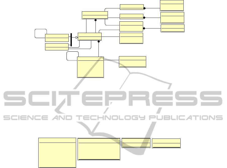
GraphDiagramType
name: String
ElemType
name: String
ElemStyle
shape: TShape
color: TColor
Pa lette
PopUpElement
caption: String
NodeType
PopUpMenu
EdgeType
Toolbar
CompartType
name: String
defaultValue: String
prefix: String
suffix: String
concat: String
Com pa rtStyle
fontSize: Integer
fontStyle: TFontStyle
PaletteElement
caption: String
image: TImage
ToolbarItem
caption: String
image: TImage
0..1
0..1
{ordered}
{ordered}
{ordered}
0..1
source *
target0..1
start0..1end0..1
parent
0..1
child *
0..1
parent
0..1
child *
1
1..*
1
1..*
Fig. 3. The very base of the Tool Definition Metamodel.
For instance, one could want to perform some specific action every time a class is
created in the UML class diagram editing tool. It can be done be writing a specific
transformation and letting the UI know its name so it can be executed right after an
element with a type name “Class” is created. This is technically done by specifying
names of these specific transformations as values of certain attributes of TDMM
classes (each attribute meaning a specific type of extension point being called at cer-
tain time). Some most important extension points can be seen in Fig. 4.
ElemType
onElemCreated: String
onClick: String
onL2Click: String
onElemDeleted: String
onElemCopied:S String
onElemPasted: String
CompartType
onClick: String
onFieldEntered: String
onCompartCreated: String
onCompartDeleted: String
PopUpElement
onClick: String
ToolbarItem
onClick: String
Fig. 4. Extension points as attributes containing the calling transformation names.
4.3 Metamodel of Advanced Stereotypes
The same idea used in GRAF TDMM about calling specific transformations at certain
times is also used in the advanced stereotype mechanism. Moreover, the metamodel
storing the needed information for stereotypes is made as an extension of TDMM.
Thus, the same extension points of TDMM can be used to specify stereotype-specific
functions while at the same time stereotypes are not the same types used in TDMM.
This distinction makes it possible to percept the profile as a separate unit and to apply
it to or remove it from a tool (that is, to some instance of TDMM) as needed. That is
one of the most beautiful features of profiles implemented this way. That also makes
the advanced stereotype mechanism different from the Configurator – although both
of them can be used to create new tools “from scratch”, advanced stereotypes are
more suitable in other aspects of a higher-order domain-specific tool like adjusting an
already existing tool. If it is to be done by the Configurator, the changes are to be
final and unremovable. Also, changes are not to be applied to other similar tools in
the case of Configurator.
21
Stereotype
name: String
ElemStyle
Profile
name: String
ElemType
Palette Ele me nt
caption: String
image: TImage
CompartStyle
CompartType
name: String
isStereotype: Boolean
1
1..*
1
1..*
attribute
parent
0..1
child *
elemStyleByStereotype
0..1
compartStyleByStereotype *
com p a rtType ByStere otype *
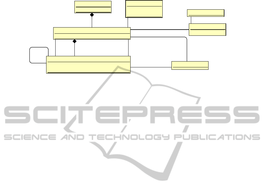
Fig. 5. Part of TDMM storing stereotype-related information.
The basic part of the metamodel storing stereotype-related information is shown
in Fig. 5. Here, some classes from the Tool Definition Metamodel are to be found –
ElemType, ElemStyle, CompartType, CompartStyle, PaletteElement. In order to
attach a stereotype definition to some element type, the element type must contain a
compartment type in which the stereotype would be chosen. The stereotype compart-
ment (the one having isStereotype = true) can then contain stereotypes as instances of
class Stereotype. Stereotype attributes are also CompartTypes linked to the stereotype
via the link attribute. As said before (sections 3.3 and 3.4), stereotypes can also inter-
fere with other compartment and element styles or other compartment types them-
selves. This information is given through links ending with ByStereotype.
Like it was explained in section 2, our intension is not only to allow users to ex-
tend the tool behavior with manually written functions, but also to make this exten-
sion possible for those end-users not knowing the technical and sophisticated tool
definition metamodel. When writing a function, one has to know only the concepts of
the language under development. A virtual view can be built for the language allow-
ing model transformations to work with it as if these concepts were really stored in
repository.
Here, a virtual view is a virtual metamodel containing classes, associations and
attributes that are familiar to the user. To avoid data redundancy, this virtual metamo-
del is not stored in the repository. Instead, transformation programs written based on
this metamodel are compiled into ones working with the real metamodels (TDMM
and others). This translation can be done automatically using the view definition
facilities provided by the person defining the view. Moreover, in the case of advanced
stereotypes, the same process of defining views can be automated in most cases. Also,
a user can interfere in this process if needed.
The view definition mechanism is however out of the scope of this paper. It is de-
scribed in more details in [13]. Here, a model transformation language L0 [14] is used
to demonstrate the approach although other languages could be used as well.
5 Related Work
Quite a lot of related work exists in the field of graphical domain-specific tool build-
22

ing. The most known are perhaps two leaders having developed commercially usable
tool-building platforms – MetaCase and Microsoft. MetaEdit+ platform [1] of Meta-
Case is somewhat very related to the GRAF framework described and used in this
paper. They also define tools using a configurator whose result is then immediately
interpreted thus making a tool to work. However, they do not provide an explicit
metamodel of this result being interpreted – the behavior of the tool is instead ex-
plained in terms of the configurator. Microsoft, on the other hand, uses a slightly
different approach in their DSL Tools [2] – the result of the configurator is to be
compiled first in order for the newly created tool to be able to work.
Also, a very popular platform for building metatools is Eclipse [15]. This platform
contains a number of standard plug-ins for supporting the tool domain. The most
advanced Eclipse plug-in for graphical tool building is Graphical Modeling Frame-
work (GMF, [16]) providing a complete tool generation for simple cases. In more
sophisticated cases, Eclipse GMF provides an option of manual code extension in
Java which can be done having a deep understanding of the generated code and GMF
runtime internals. One more tool to be mentioned based on the Eclipse platform is
METAclipse [17]. METAclipse uses explicit presentation and domain metamodels
and maintains a mapping between them. All the logic of the tool is put into model
transformations. A compiler is then used to obtain the new tool.
Other metacase tools relying on the same configurator-like principle are Pouna-
mu/Marama [18, 19], ViatraDSM [20] and Tiger [21].
Also, there exist some products providing a way of defining domain-specific lan-
guages and tools through UML stereotype mechanism. IBM in its Rational Software
Architect (RSA, [22]) provides facilities for defining a profile containing of UML-
like stereotypes. A stereotype is defined as a subclass of the base type, so new
attributes can be added to stereotypes. However, these attributes can only be entered
through dialog window and used from transformations, but they are not to be pre-
sented visually in the diagram. Also, a visual appearance of the base element can be
changed using stereotypes while the appearance of attributes can’t.
Another tool using UML profiling facilities to develop domain-specific languages
is MagicDraw by No Magic company [23]. Like in both RSA and the tool described
in this paper, in MagicDraw a new tool can also be made through stereotypes leaving
no resemblance of how the original base looked like – base concepts can be hidden
from palette as well as base attributes can be hidden from the dialog window (default
values can be provided for them if needed). Also, an OCL [24] interpreter is inte-
grated in RSA and MagicDraw allowing one to add some constraints to the tool. In
RSA, additional constraints can be written in Java.
6 Conclusions and Future Work
Although many platforms exist nowadays providing one possibility to build a do-
main-specific tool adjusted to exactly his/her needs, the usability of those platforms
differs quite a lot. Our intention in this paper was to study some of those platforms
and to come out with a solution of how to ease the definition of domain-specific lan-
guages and tools from the end user point of view. Unlike many other platforms, we
23

stressed the necessity to not only define new tools but also to adjust existing tools
whose definitions may be inaccessible to us. As a result, we have developed a higher-
order domain-specific language (together with a tool implementing it) for managing
other domain-specific tools. In this paper, basic ideas of how to make such language
are explained.
The language is based on UML stereotype-like mechanism which is extended with
several facilities. A simple tool can be created as a profile of some other tool by click-
ing mouse buttons and entering some minor information where needed. To create
more sophisticated tools, the extension mechanism is available providing a possibility
to extend the tool functionality through manually written function calls. The process
of writing the functions in a model transformation language is also lightened by inte-
grating a view mechanism in the platform – the user can write functions in familiar
terms (the ones of the language being created), and the transformation is then com-
piled to one working with the real technical metamodel.
Since no tool-building platform can ever be final and perfect, our plans for the
near future include continuing to improve the advanced stereotype language and tool.
One of the most significant improvements regarding usability of the language is the
use of several model transformation languages at once. Currently, it is allowed to use
one transformation language for writing tool extending functions, and we use the
language L0 to demonstrate the approach. In the future, several functions are to be
possibly written in several different languages which will improve the usability of the
platform significantly. Another meaningful improvement would be the replacement of
function compiler with an interpreter allowing one to increase the speed of develop-
ing a tool – functions provided at extension points would have an immediate effect on
behavior of the tool, and also the end user (the one using not developing the tool)
would be able to change some behavior aspects.
References
1. MetaEdit+ Workbench User’s Guide, Version 4.5, http://www.metacase.com/
support/45/manuals/mwb/Mw.html , 2008.
2. S. Cook, G. Jones, S. Kent, A. C. Wills. Domain-Specific Development with Visual Studio
DSL Tools, Addison-Wesley, 2007.
3. M. Tisi, F. Jouault, P. Fraternali, S. Ceri, J. Bezivin. On the Use of Higher-Order Model
Transformations. Lecture Notes in Computer Science, Vol. 5562, 2009, pp. 18-33.
4. OMG modeling specifications, UML 2.1.1 Superstructure and Infrastructure,
http://www.omg.org/docs/formal/07-02-05.pdf
5. A. Sproģis, R. Liepiņš, J. Bārzdiņš, K. Čerāns, S. Kozlovičs, L. Lāce, E. Rencis, A. Zariņš.
GRAF: a Graphical Tool Building Framework. Proceedings of the Tools and Consultancy
Track. European Conference on Model-Driven Architecture Foundations and Applications,
Paris, France, 2010, pp. 18-21.
6. J. Barzdins, S. Kozlovics, E. Rencis. The Transformation-Driven Architecture. Proceedings
of DSM’08 Workshop of OOPSLA 2008, Nashville, USA, 2008, pp. 60-63.
7. Meta Object Facility (MOF) Core Specification v2.0, OMG, document formal/06-01-01,
2006.
8. Eclipse Modeling Framework (EMF, Eclipse Modeling subproject),
http://www.eclipse.org/emf
24

9. J. Barzdins, A. Zarins, K. Cerans, A. Kalnins, E. Rencis, L. Lace, R. Liepins, A. Sprogis,
GrTP: Transformation Based Graphical Tool Building Platform, MODELS 2007, Work-
shop on Model Driven Development of Advanced User Interfaces, 2007.
10. J. Barzdins, K. Cerans, S. Kozlovics, E. Rencis, A. Zarins. A Graph Diagram Engine for
the Transformation-Driven Architecture. Proceedings of MDDAUI’09 Workshop of Inter-
national Conference on Intelligent User Interfaces 2009, Sanibel Island, Florida, USA,
2009, pp. 29-32.
11. J. Barzdins, K. Cerans, S. Kozlovics, L. Lace, R. Liepins, E. Rencis, A. Sprogis, A. Zarins.
MDE-based Graphical Tool Building Framework. Scientific Papers, University of Latvia,
“Computer Science and Information Technologies”, Vol. 756, 2010, pp. 121-138.
12. A. Sprogis. The Configurator in DSL Tool Building. Scientific Papers, University of Lat-
via, “Computer Science and Information Technologies”, Vol. 756, 2010, pp. 121-138.
13. E. Rencis. On Views on Metamodels. Databases and Information Systems VI, Selected
Papers from the Ninth International Baltic Conference, DB&IS 2010, pp. 94-107.
14. J. Barzdins, A. Kalnins, E. Rencis, S. Rikacovs, Model Transformation Languages and
their Implementation by Bootstrapping Method. Pillars of Computer Science, Lecture
Notes in Computer Science, Vol. 4800, Springer-Verlag, 2008, pp. 130-145.
15. Eclipse. http://www.eclipse.org
16. Graphical Modeling Framework (GMF, Eclipse Modeling subproject),
http://www.eclipse.org/gmf
17. A. Kalnins, O. Vilitis, E. Celms, E. Kalnina, A. Sostaks, J. Barzdins, Building Tools by
Model Transformations in Eclipse. Proceedings of DSM’07 workshop of OOPSLA 2007,
Montreal, Canada, Jyvaskyla University Printing House, 2007, pp. 194-207.
18. Nianping Zhu, John Grundy, and John Hosking, Pounamu: a meta-tool for multi-view
visual language environment construction, 2004 IEEE Symposium on Visual Languages
and Human Centric Computing (VLHCC’04), 2004, pp. 254-256.
19. John Grundy, John Hosking, Jun Huh, Karen Na-Liu Li, Marama: an Eclipse Meta-toolset
for Generating Multi-view Environments, ICSE’08, Leipzig, Germany, 2008.
20. I. Rath, D. Varro, Challenges for advanced domain-specific modeling frameworks. Proc. of
Workshop on Domain-Specific Program Development (DSPD), ECOOP 2006, France.
21. C. Ermel, K. Ehrig, G. Taentzer, E. Weiss, Object Oriented and Rule-based Design of
Visual Languages using Tiger. Proceedings of GraBaTs'06, 2006, pp. 12.
22. Rational Software Architect, http://www.ibm.com/developerworks/retional/products/rsa
23. MagicDraw, http://www.magicdraw.com
24. UML 2.0 OCL Specification, OMG, document ptc/03-10-14, 2003.
25
