
A Study of the Impact of Computational Delays in Missile
Interception Systems
Ye Xu, Israel Koren and C. M. Krishna
Department of Electrical and Computer Engineering, University of Massachusetts at Amherst, Amherst, MA 01003, U.S.A.
Keywords: Computer Response Time, Computational Delay, Single-missile Single-target System, Multiple-missile
Multiple-target System.
Abstract: Most publications discussing missile interception systems assume a zero computer response time. This
paper studies the impact of computer response time on single-missile single-target and multiple- missile
multiple-target systems. Simulation results for the final miss distance as the computer response time
increases are presented. A simple online cooperative adjustment model for multiple-missile multiple-target
system is presented for the purpose of studying the computer delay effect.
1 INTRODUCTION
Computational delay is a key determinant of
performance in a cyber-physical system. The
computer is in the feedback loop of the controlled
plant; any additional delay may degrade the quality
of control. The impact of computational delays has
not been adequately addressed in the literature. In
this paper, we use as an example a tracking system
for missile control. The dynamics of such systems
have been well-studied in the literature (under the
tacit assumption that the computational delays are
zero); we focus on the impact of computational
delays in such a problem.
In this work, computational delay (or computer
response time) refers to the time that elapses from
the point the control algorithm is triggered to the
point that the control signal is generated.
The paper is organized as follows: Section 2
provides the basic background including the widely
used guidance laws, and presents the simulation
results for a single-missile single-target system. In
Section 3, a simple but still effective model for an
online adjustment algorithm is described. Section 4
presents simulation results for the multiple-missile
multiple-target system, focusing on two aspects: the
effectiveness and advantages over the single-missile
single-target system, and its ability to handle the
computational delay during flight time. Section 5
presents conclusions and future work.
2 SINGLE MISSILE SINGLE
TARGET SYSTEM
This section briefly summarizes the principles of
some classic guidance laws, and presents simulation
results for a single-missile single-target system.
The typical guidance laws that are implemented
in missile guidance systems are the Proportional
Navigation Guidance (PNG), and its more advanced
counterpart, the Augmented Proportional Navigation
Guidance (APNG). PNG is one of the most widely
used guidance laws in homing air target missile
systems. The main underlying assumption is that if
two vehicles are on a collision course, their direct
Line-of-Sight (LOS) does not change direction or
value. Generally speaking, PNG indicates that the
missile velocity direction should rotate at a rate
proportional to the turn rate of the LOS, and should
be in the same direction.
Figure 1: Missile-Target Intercept Geometry.
Typical parameters in this geometry (see Figure
1) can be found in (P. Zarchan, 2007):
585
Xu Y., Koren I. and M. Krishna C..
A Study of the Impact of Computational Delays in Missile Interception Systems.
DOI: 10.5220/0004011705850588
In Proceedings of the 9th International Conference on Informatics in Control, Automation and Robotics (ICINCO-2012), pages 585-588
ISBN: 978-989-8565-21-1
Copyright
c
2012 SCITEPRESS (Science and Technology Publications, Lda.)

L+HE: where L is the Missile Lead Angle and
HE is the Heading Error.
R: Length of the line of sight (LOS)
: Missile Acceleration;
Missile Velocity
Angle of Line of Sight (LOS)
: Target Heading;
Target Velocity
Target Maneuver (i.e., target acceleration
normal to its velocity.)
The Proportional Navigation Guidance law
(PNG) can be stated as (P. Zarchan, 2007):
(1)
There are more advanced guidance laws that can
yield smaller miss distances against a highly
maneuvering target, where the miss distance is
measured at the point of closest approach of the
missile and target. One of these advanced guidance
laws is the Augmented Proportional Navigation
(APNG) (P. Zarchan, 2007):
(2)
APNG is a proportional navigation with an extra
term to account for the maneuvering target.
2.1 Model Assumptions
The missile and target model assumptions used in
this paper (for both single and multiple cases) are:
• No noise
• Target is a mass point
• Missile is a rigid body, influenced by
aerodynamic forces (has velocity reduction), and
the missile airframe is a 1
st
order system with a
time constant of 1 and the transfer function:
• Target escape range: once the relative distance at
this time between the target and missile is less
than this range, the target starts to escape
• Target maneuvering: 10g
• Missile maneuvering saturation: 3 times as much
as target maneuvering.
• Initial Target velocity: 1000m/s
• Missile Initial Velocity: 4000 m/s.
2.2 Simulation Results for
Single - Missile Single - Target
System
Below are several simulation results based on the
above assumptions; note that the problem of
computational delay is made more acute by the fact
that, quite often, relative slow processors are used in
control functions. Figures 2 and 3 show that with a
higher computer response time, the final miss
distance would get worse. Figure 4 shows the
relationship between the final miss distance and the
computer response time.
As Figure 4 shows, the final miss distance would
increase but at slower rate as the computer response
time keeps increasing.
Figure 2: The trajectories of the missile and the target for a
computer response time of 0.01s.
Figure 3: The trajectories of the missile and the target for a
computer response time of 0.1s.
Figure 4: The miss distance as a function of the computer
response time for different relative ranges at which the
target starts to escape.
Moreover, the miss distance will reach a
“saturation region” if the response time increases to
a very large value. If the computer is significantly
slow, the missile would never make any adjustments
online, and would follow a straight line flight path as
it is launched at ground. Thus, once beyond the point
at which the computer is too slow to generate any
ICINCO 2012 - 9th International Conference on Informatics in Control, Automation and Robotics
586

command signal, the final miss distance would stay
the same.
3 MULTIPLE TARGETS
COOPERATIVE SYSTEM
The analysis above is for a single-missile
single-target system. In this section we present a
simple but still effective online adjustment algorithm
for the case of a multiple-missile multiple-target
system for the purpose of studying the impact of the
computer response time. Since there are only very
few prior publications about multiple-missile
multiple-target systems in the open literature, we
had to create our own simple model to study the
effect of computer response time.
Our algorithm enables cooperation among the
missiles to control the following three parameters
during the flight time: (i) which target would be
engaged by each missile; (ii) which guidance law to
employ; and (iii) which guidance parameters should
be used by the guidance law. The guidance laws
considered here are PNG and APNG.
3.1 Online Cooperation
The proposed Online Cooperative Adjustment
Algorithm (OCAA) has three sub tasks. The solution
vector includes three elements: the index of
the target that this missile should engage, the
guidance law this missile should employ, and the
guidance law parameter the missile should use. We
have used in our experiments two guidance laws,
PNG and APNG, with index 0 (1) indicating the use
of PNG (APNG).
The first sub task is a periodic task, passing the
current missile’s last solution vector to the missile
computer, and evaluating this solution. The on-board
computer would check two conditions at this time:
(1) whether the final estimated miss distance using
the last solution vector would be within the missile’s
explosion range, (2) whether other missiles sent a
switch target request (see below). If both are false,
the missile continues using the last solution vector.
The second subtask is: if during the online
evaluation the missile finds out that the last solution
vector cannot guarantee a hit, the computer would
generate a switch target request signal to other
missiles. At the same time, the computer would also
generate new solution vectors for each missile target
pair, and save all the available solution vectors for
later use, as well as generate the information vector
showing which target the current missile can hit, to
be sent to the other missiles.
The third sub task is: after every missile gets the
information vectors from all other missiles, all
missiles would combine these vectors into an
information table. Then, each missile’s on board
computer would make a missile-target assignment
using the same assignment algorithm. This finishes
the online adjustment and the missile computer
would return to sub task one.
4 RESULTS FOR MULTIPLE
MISSILE-TARGET SYSTEM
In order to study the computational delay impact for
the multiple missile case, it is helpful to compare it
with traditional PNG. Below are several results
showing a 3-missile and 3-target engagement
system. Suppose that the target and missile models
are the same as in the single missile system and the
target escape times (after which the target starts to
escape) for targets 1, 2 and 3, are 15s, 14s, and 15s,
respectively; and the target maneuvering levels are
15g, 20g and 10g, respectively. The missile
explosion range is 30 meters.
Figure 5: Simulation results for PNG, with a computer
response of 0.01s. Blue (Red) lines are missile (target)
trajectories. Once the missile enters its explosion range, it
explodes, and this missile and its target stop moving.
Figure 5 shows that all of the missiles and targets
never stop moving, which means none of the
missiles ever enters their explosion range. The
detailed final miss distance for each missile target
pair is shown in Table 1. As we can see in Figures 6
and 7 a multiple-missile multiple-target system
using communication and online cooperation, could
achieve a better performance than a single-missile
single-target system where each missile employs its
initial algorithm without online cooperation.
A Study of the Impact of Computational Delays in Missile Interception Systems
587
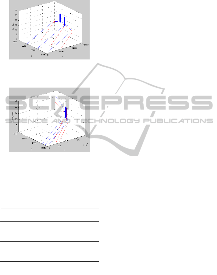
Figure 6: Simulation results for OCAA with a computer
response time of 0.01s. Around 17s to 18s all three
missile-target pairs stop moving, i.e., all three missiles
entered their explosion range and hit their targets.
Figure 7: Simulation results for OCAA with computer
response time of 0.05s. Two missile-target pairs stop
moving, while one pair never stops, i.e., two missiles hit
their targets, and one missile misses its target.
Table 1: Performance in terms of computer response time;
“hit” (“miss”) means that the final miss distance is within
(outside) the missile explosion range.
Computer response time
(seconds)
Final result for all
targets
0.01
all hits
0.02
all hits
0.03
all hits
0.04
all hits
0.05
2 hits, 1 miss
0.1
2 hits, 1 miss
0.2
2 hits, 1 miss
0.3
2 hit, 1 misses
0.4
1 hit, 2 misses
0.5
three misses
Moreover, Table 1 also shows that a multiple missile
and target system can handle the problem of
computational delay well. All three missiles are
within their explosion range (of 30 meters) even for
a delay time of 0.05s. Also, not all targets are missed
until the computer response time is as large as 0.5
seconds, an unlikely case for modern computers
5 CONCLUSIONS
The computer response time for missile guidance
(and other computer algorithms in the missile
airframe) is generally ignored in previous papers in
the open literature. This paper studies the impact of
computational delay for both single-missile
single-target system and multiple-missile multiple
-target system.
Future work may include a more realistic missile
and target model, noise in the sensor, a more
sophisticated online cooperation algorithm, and
additional physical limitations. For the latter, this
paper uses a simplified missile and target model,
assuming that the actuators are perfect without
internal mechanical delay, and assuming that the
missile and target airframe model are first order
systems. A more realistic model could be used for
more accurate results.
ACKNOWLEDGEMENTS
This work was partially supported by the National
Science Foundation under grant CNS-0931035.
REFERENCES
Shin, K. G., and Cui, X., 1995. Computational Time Delay
and Its Effects on Real-Time Control Systems, IEEE
Transactions on Control System Technology, Vol. 3,
No. 2, pp. 218 – 224.
M. Wei, G. Chen, J. B. Cruz, Jr, and E. Blasch, 2008.
Multi-Missile Interception Integrating New Guidance
Law and Game Theoretic Resource Management”,
IEEEAC paper#1390, Version 7.
E. J. Hughes, 2002. Evolutionary Guidance for Multiple
Missiles, World Congress, Volume 15, Part 1.
P. Zarchan, 2007. Tactical and Strategic Missile Guidance,
AIAA, 5th edition.
M. Guelman, 1972. Proportional navigation with a
maneuvering target, IEEE Transactions on Aerospace
and Electronic Systems, No. 3.
P. B. Jackson, 2010. Overview of Missile Flight Control
Systems, John Hopkins APL Technical Digest, Vol.29,
No. 1.
ICINCO 2012 - 9th International Conference on Informatics in Control, Automation and Robotics
588
