
A Mobile Service Robot for Industrial Applications
Luca Lattanzi
1
, Giacomo Angione
1
, Cristina Cristalli
1
, Florian Weisshardt
2
,
Georg Arbeiter
2
and Birgit Graf
2
1
Research for Innovation Department, AEA srl, Loccioni Group, Ancona, Italy
2
Robot System Department, Fraunhofer IPA, Stuttgart, Germany
Keywords: Robot Design, Development and Control, Mobile Robots and Intelligent Autonomous Systems,
Autonomous Agents, Vision, Recognition and Reconstruction, Service Robotics.
Abstract: This paper addresses the challenge of introducing mobile robots in industrial applications, where changes in
the working environment and diversification of tasks require flexibility, adaptability and in some cases basic
reasoning capabilities. Classical industrial robots hardly permit to meet these requirements, so a new
concept of service robots facing challenging industrial production system needs is proposed. The realization
of such an autonomous agent is illustrated and described in details, focusing on mobility, environmental
perception and manipulation capabilities. The result is a mobile service robot able to face changeable
conditions as well as unexpected situations and different kinds of manipulation tasks in industrial
environments. In this paper an implementation dedicated to household appliances production is described,
but the results achieved can be easily extended to many industrial sectors, goods and electromechanical
components where high levels of flexibility and autonomy are needed.
1 INTRODUCTION
At the state of art, robot applications are usually
divided into two main categories: industrial robotics
and service robotics (Bekey and Yuh, 2008). In the
past these two fields were widely unrelated and
disconnected so that they were considered as fully
independent from each other. Industrial robots
mainly operate in highly structured environments,
and they are not able to adapt to frequent changes
and variations in the environment. On the other
hand, nowadays, systems able to cope with flexible
and complex tasks in changeable environments, as
well as with uncertainties and unpredictable
modifications of the working area can be widely
found in the field of service robotics: e.g. Care-O-
bot (Reiser et al., 2009), PR2 (Bohren et al., 2011)
and many more.
Although recent evolution in sensors technology
and modern developments in control algorithms
(Wang and Li, 2009) have brought to an extensive
variety of service robots, very few of them seem to
deal with the support of industrial processes
(Hamner et al., 2010). Therefore, all the progress
achieved in the service robotics domain has not yet
fully exploited in the industrial field. For example, a
closer interaction between robots and humans inside
the production environment is still an open issue but
it could be solved using techniques fully exploited in
service robotics applications, thus permitting the
sharing of the same working area between robots
and humans.
Industries need robotic systems which are
flexible, modular and easily customizable to the
requirements of different production processes. A
mobile robot with manipulation capabilities
represents a valid solution for achieving the level of
flexibility required by modern industrial processes
(Kroll and Soldan, 2010). Most of the possible
alternative solutions, like gantry mechanisms or
robots running on conveyor systems need a highly-
structured environment, and they could turn out to
be completely useless in the case of environment
changes.
Nowadays mobile robots applied in industrial
applications mainly belong to the group of AGVs
(Automated Guided Vehicles) with their main
purpose to transport objects from one location to
another. They mostly follow pre-programmed paths
and are able to react to their environment only in a
limited way: usually the robot stops in case its
298
Lattanzi L., Angione G., Cristalli C., Weisshardt F., Arbeiter G. and Graf B..
A Mobile Service Robot for Industrial Applications.
DOI: 10.5220/0004041602980303
In Proceedings of the 9th International Conference on Informatics in Control, Automation and Robotics (ICINCO-2012), pages 298-303
ISBN: 978-989-8565-22-8
Copyright
c
2012 SCITEPRESS (Science and Technology Publications, Lda.)
sensors perceive an obstacle in its path. First systems
of AGVs with attached robotic arms have been set
up in Japan (Hibi, 2003). While robotic arms deliver
high flexibility, until now there are still unsolved
problems considering energy consumption, weight
and safety. In this way, AGVs equipped with robotic
arms are not wide spread especially in Europe and
they are applied only to very specific domain like
offshore platforms (Bengel et al., 2009).
Another major challenge in using a mobile robot
in an industrial environment is to ensure collision-
free operations in order not to endanger humans
sharing the work space and not to crash against
unexpected obstacles in the working area. Safe
human-robot cooperation is a mandatory topic that
has to be considered and assured for this kind of
applications. Mobile robots like AGVs are able to
move safely in their environment. This is realised by
various sensors (mainly bumpers, plastic brackets
and laser scanners) ensuring that no collision occurs
(Ikuta and Nokata, 1999). The safety of robot arms,
however, is mostly still ensured by separating their
work areas from humans with fences. Safe human
robot interaction according to ISO 10218 requires
special safety controllers and additional devices such
as safety sensors or dead man switches. So far, no
industrially used implementations to detect and
avoid collisions of robot arms have established in
either unknown or changing environments without
using fences (Oberer and Schraft, 2007).
This paper is going to present a mobile system
achieving a degree of autonomy and flexibility
typically found on robots belonging to the service
robotic field but specifically conceived for working
in industrial scenarios.
2 SYSTEM OVERVIEW
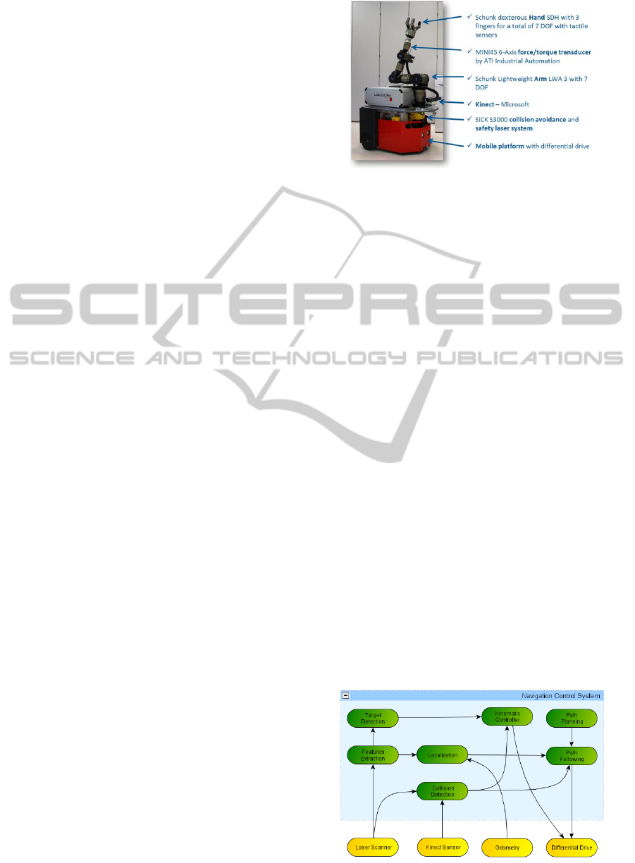
The developed system is a mobile service robot with
manipulation and environmental perception
capabilities, conceived to work in industrial
environments with a high degree of autonomy and
flexibility (Figure 1). The robot is able to:
- Move safely and autonomously in an
industrial environment following predefined
paths, avoiding obstacles and collisions,
detecting targets and reaching objects;
- Reconstruct a 3D model of the working
environment and recognize relevant features;
- Interact with objects in the surrounding
environment performing operations like
grasping, pushing buttons, turning knobs and
opening / closing doors;
Figure 1: Overview of the developed mobile service robot.
- Place advanced sensors (digital cameras,
distance sensors, tactile sensors, temperature
sensors, pressure & sound sensors, etc.) in
order to gather new information;
- Acquire, analyse and collect data.
3 NAVIGATION CONTROL
The key aspect of an autonomous mobile robot is
represented by its ability to freely move in the
working area, localizing in the environment,
checking for possible obstacles along the planned
path and avoiding collisions during motion. Figure 2
describes the overall architecture of the implemented
navigation control system. The most important
modules are described in the following subsections.
3.1 Obstacle Detection
Collisions avoidance during robot motion is based
on SICK Laser Scanner and Microsoft Kinect
sensors. Kinect 3D sensors, covering the floor area
close to the robot, are used to sense obstacles which
are not visible with the laser scanner (e.g. a table
plate). The raw data acquired from these sensors is
filtered so that only relevant obstacles in the driving
direction are taken into account for the collision
model. The raw point cloud is transformed into the
Figure 2: Navigation control system.
A Mobile Service Robot for Industrial Applications
299
robot base coordinate system and further filtered to
remove points that are in the ground and beside or
above the robot. With the help of the odometry
information which specifies driving direction and
speed, the minimum stopping distance for the robot
is calculated.
The safety distances can be adapted according to
the environment the robot is working in and depend
on the speed of the robot. If an obstacle is detected,
the robot will be stopped in order to plan a new path
for avoiding the object.
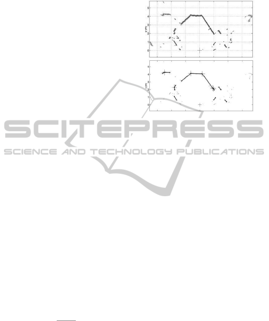
3.2 Environmental Feature Extraction
By filtering and processing data acquired from the
laser scanner mounted on the robot, the system is
able to detect spatial primitives in the working
environment (corners, straight lines and reflective
landmarks). The line extraction algorithm
implemented is similar to the one described in
Armesto and Tornero (2006) and it is based on two
steps: split and merge. During the splitting step if the
distance between two consecutive points acquired by
the laser scanner is below a certain threshold the
points will be considered as members of the same
cluster, otherwise they belong to different ones.
Inside the same cluster the Least Mean Square
(LMS) algorithm is used to find the segment that
approximates the position of the points. During the
merging step if consecutive segments are close and
aligned, they are approximated with another segment
including both. The merging step is repeated until
there are no more segments to merge. In Figure 3 the
result of applying the line extraction algorithm to
data acquired by the laser scanner is depicted.
3.3 Robot Localization
Localization presumes that the mobile system is able
to recognize environmental features like walls,
corners, columns. In the implemented algorithm, the
capability of the laser scanner to detect reflecting
markers is exploited. In order to avoid detection
errors, consecutive reflective points are considered
markers only if:
where is the number of consecutive reflective
points,
is the diameter of the marker
is the laser scanner resolution and is the distance
between the laser and the reflective surface. Once
markers are recognized by the features extraction
algorithm, they are added to the environmental map
Figure 3: Data processing for lines extraction (upper: raw
data, lower: processed data).
and then used in the localization process. The
localization algorithm is based on a standard
implementation of the Kalman Filter (Welch and
Bishop, 2006), and it is composed of the two
classical steps:
1. Prediction: the system forecasts the increase of
the position error due to the inaccuracy of the
encoders. The result of this step is the position
of the robot plus an uncertainty level.
2. Correction: Kalman Filter is used to correct
and reduce the position uncertainty using the
position of the markers that have been detected.
4 MANIPULATION CONTROL
SYSTEM
The following section will focus on the manipulator
control system that makes the robot able to safely
operate and interact with objects in the working
environment.
4.1 3D Modelling for Arm Collision
Detection
Detecting obstacles in the proximity of the robot and
considering them in the movement planning phase
allow the robot to operate its arm also in narrow
environments. When the robot needs to move its
arm, a collision-free path to reach the goal position
is planned. All the movements of the arm have to be
self collision free, which means that the arm should
not collide with any other part of the robot. For this
reason, a 3D model for the arm and the mobile base
ICINCO 2012 - 9th International Conference on Informatics in Control, Automation and Robotics
300

is used for collision checking: collisions between
single joints composing the arm as well as between
the arm and the mobile base (and with other robot
components) are checked. This step is based on the
internal joint sensors of the arm, so the robot knows
about its own current configuration and its
dimensions. Another important aspect is to check
collisions against the environment. Industrial
working environments, where the robot could be
used, are not static, so the robot has to deal with
dynamic obstacles. To supervise the arm two PMD
CamBoard are used; one is directly mounted on the
arm, while the other on the mobile base. To not
detect the robot parts themselves as obstacles a robot
self-filter is setup removing the robot parts from the
3D point cloud.
4.2 Manipulation
For the proper execution of an interaction task, the
target coordinates of the object to be manipulated
(that are expressed with reference to the sensors
coordinate system) are transformed into the Tool
Center Point (TCP) reference system of the arm.
Then the arm moves in front of the target using
inverse kinematics, arm planning and collision
checking against the above mentioned 3D robot and
environment model. The manipulation system is set
in order to pre calculate all arm movements taking
into account the 3D environment model. Only if all
movements and target positions can be reached, the
execution is started. In that way it is assured that the
arm does not need to be stopped in the middle of a
task because of reachability issues. Nevertheless the
arm will be stopped due to safety issues, e.g.
collision sensed with the tactile or FT sensors.
As a manipulation task requires physical contact
between the end-effector and the object, in the
“contact phase” of the task it is not possible to use
the planning with collision checking approach
described in the previous paragraph. Touching the
target with the end-effector of the arm would be
considered of course as a collision. Therefore the
arm moves just in front of the target object and then
the manipulation mode changes in order to move
very slowly to a pose which is already inside the
target. The arm will stop as soon as the contact is
detected by tactile or force-torque sensors. This
approach avoids problems due to inaccuracy in the
depth information acquired by the 3D sensor and
prevents damages to the target objects and the robot
itself. Furthermore using the above strategy the
robot is able to safely execute the desired operation
even within a changing environment.
5 APPLICATION SCENARIO
AND EXPERIMENTAL
RESULTS
The capabilities of the proposed robot have been
fully tested and validated in a specific industrial
application scenario: the reliability control in life-
test laboratories of household appliances.
5.1 Scenario Description
Today in washing machine (WM) life-test
laboratories, machines functional performances are
usually recorded, such as the quantity of water and
energy consumed. The level of automation of such
tests is relatively low; in most cases, human
operators are in charge of loading the machines with
cloths, starting the washing cycle and periodically
controlling that no failure occurs. Once a failure
occurs, the number of washing cycles until failure is
recorded and fed as input to the following reliability
analysis (together with the type of failure).
With respect to this context, the developed
mobile robot can be equipped with additional
measurement sensors (in particular a laser
vibrometer, a microphone and a high resolution 2D
camera) in order to properly inspect the working
behaviour of a washing machine. In the described
scenario, such a “diagnostic service robot”
represents an excellent solution because it satisfies
the needs of standards and repeatability of the
quality controls and guarantees flexibility according
to the product under diagnosis and the environment
where the test is executed (Concettoni et al., 2011).
5.2 Products Detection and Approach
In order to autonomously achieve its diagnostic task,
the robot needs to recognize washing machines in
the environment and reach the machine to test
(Raffaeli et al., 2012).
The feature extraction algorithm described in
Section 3.2 is used to detect both front and side faces
of the washing machine. Knowing the WM
geometrical data (depth and thickness), the position
of the center of the potential washing machine is
calculated and this value is compared with its
expected position (the nominal position of the
machine is known from the map of the laboratory).
Only if these values match (with an appropriate error
tolerance) the object detected will be considered as
the washing machine to test, and the final target
position of the robot (as well as its orientation) is
A Mobile Service Robot for Industrial Applications
301
calculated (Figure 4). The results obtained applying
the “detection and approach” algorithm are shown in
the first sector of Table 1.
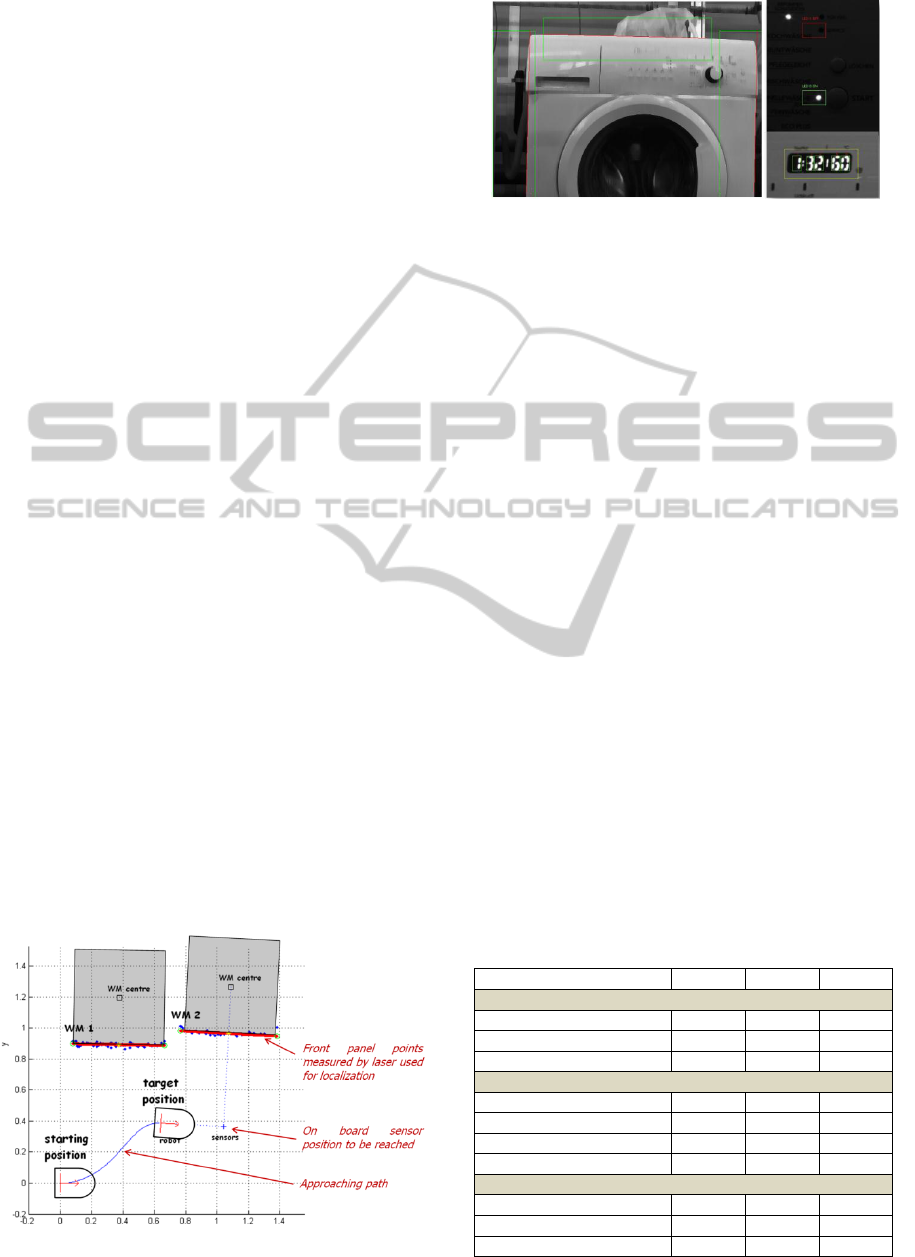
5.3 Products Visual Inspection
As the diagnostic procedure depends on the actual
working condition of the product to test, based on
data collected by the 2D camera the system is able to
correctly recognize the WM functional status (off,
washing, etc.). The acquired image is first filtered
and processed, so that effects of reflections and light
variations can be minimized. First, a median filter is
applied to the image, as to increase edges contrast.
Then a Laplacian of Gaussian (LoG) smoothing
technique is used in order to further highlight edges.
Next, the filtered image is processed in order to
detect the washing machine edges (top, right and
left). At this point, the washing machine features
defined in the front panel map (known by the robot
as the panel maps of all washing machine models to
inspect are stored in the reliability laboratory
database) are relocated in the new reference system
of the acquired image. Machine vision algorithms
are used to check whether the LEDs are ON or OFF,
and to get the characters visualized in the display (if
present in the front panel). Figure 5 shows an
example of visual inspection of a particular model of
washing machine. The results obtained applying the
visual inspection algorithms are shown in the second
sector of Table 1.
5.4 Products Interaction
In order to acquire useful diagnostic data from the
washing machine under test, the robot could need to
interact with the front panel of the appliance. In this
particular application scenario, the manipulation
capabilities of the robot allow to push buttons,
turning knobs and opening doors.
Figure 4: Robot motion planning for a WM approach.
Figure 5: WM edge recognition (left) and panel inspection
(right).
Whenever a manipulation task is required, the
robot detects with the laser scanner the corner of the
washing machine (using the line extraction
algorithm described in Section 3.2 and Section 5.2)
and then, from the map of the front panel (stored in
the reliability laboratory database) the position of the
feature is relocated in the arm reference system. This
algorithm permits to achieve the required accuracy
in the position estimate of the desired feature.
Moreover, every movement of the arm (except the
very last part of the interaction with the washing
machine front panel) is monitored by the “collisions
checking” module, as to prevent collisions with
obstacles in the environment. The final part of Table
1 summarizes the results obtained in the execution
of the interaction tasks.
6 CONCLUSIONS AND FUTURE
WORK
In this paper the development of a service robot for
industrial applications has been presented, focusing
on the main aspects related with autonomous
systems development: navigation, perception and
physical interaction with the real world.
Table 1: Experimental results for WM detection and
approach, visual inspection and interaction tasks.
WM#1
WM#2
WM#3
WM DETECTION AND APPROACH
Detection failure rate
<1 %
1 %
1 %
Position detection error
0.02 m
0.03 m
0.03 m
Approach position error
0.03 m
0.05 m
0.04 m
VISUAL INSPECTION FAILURE RATES
Edge detection
4 %
3 %
4 %
LED ON detection
1 %
2 %
2 %
LED OFF detection
1 %
2 %
2 %
Display char detection
5 %
n. d.
n. d.
INTERACTION TASKS FAILURE RATES
Push button
3 %
2 %
2 %
Turn knob
n. d.
4 %
5 %
Open door
n. d.
2 %
n. d.
ICINCO 2012 - 9th International Conference on Informatics in Control, Automation and Robotics
302

The main novelty of the proposed solution is a
system that can guarantee high flexibility and
effectiveness own to its mobile nature. A real
application scenario was defined in order to fully
validate and deeply test the system, and the results
show its capabilities as well as its reliability.
Next activities aim at testing innovative
approaches related to perception of the environment,
in order to improve the navigation and interaction
capabilities of the system. Future works will include
the implementation of Particle Filtering techniques
and fusion of multimodal sensor data (LRF data, 3D
sensors data and 2D camera images). Issues
concerning human-robot interaction and safety will
be improved and refined. Robot manipulation
capabilities will be also increased, making the
system able to perform additional tasks.
ACKNOWLEDGEMENTS
This work has been partly financed by the EU
Commission, within the research contract FP7 –ICT-
ECHORD.
REFERENCES
Armesto, L., Tornero, J., 2006. Robust and efficient
mobile robot selflocalization using laser scanner and
geometrical maps. Proc. IEEE/RSJ International
Conference on Intelligent Robots and Systems.
Beijing, China.
Bekey, G., Yuh J., March 2008. The Status of Robotics.
Robotics & Automation Magazine, IEEE, vol.15, no.1,
pp.80-86.
Bengel, M., Pfeiffer, K., Graf, B., Bubeck, A., Verl, A.,
2009. Mobile robots for offshore inspection and
manipulation. Proc. IEEE/RSJ International
Conference on Intelligent Robots and Systems. St.
Louis, MO, USA.
Bohren, J., Rusu, R. B., Jones, E. G., Marder-Eppstein, E.,
Pantofaru, C., Wise, M., Mösenlechner, L., Meeussen,
W., Holzer, S., 2011. Towards autonomous robotic
butlers: lessons learned with the PR2. Proc. IEEE
International Conference on Robotics and
Automation. Shanghai, China.
Concettoni, E., Cristalli, C., Paone, N., Castellini, P.,
Serafini, S., Chiariotti, P., 2011. Diagnostic robot for
vibro-acoustic measurements in accelerated life tests.
Proc. International Conference on Structural
Engineering Dynamics. Tavira, Portugal.
Hamner, B., Koterba, S., Shi, J., Simmons, R., Singh, S.,
January 2010. An autonomous mobile manipulator for
assembly tasks. Autonomous Robots, Vol. 28, Issue 1.
Hibi, H., 2003. An autonomous production system that
coexists harmoniously with human - Development of
autonomous mobile robot system. Proc. IEEE
International Conference on Robotics and
Automation. Taipei, Taiwan.
Ikuta, K., Nokata, M., May 1999. General evaluation
method of safety for human-care robots. Proc. IEEE
International Conference on Robotics and
Automation. Detroit, MI, USA.
Kroll, A., Soldan, S., 2010. Survey results on status, needs
and perspectives for using mobile service robots in
industrial applications. Proc. 11
th
International
Conference on Control Automation Robotics & Vision.
Singapore.
Oberer, S. and Schraft, R. D., April 2007. Robot-dummy
crash tests for robot safety assessment. IEEE
International Conference on Robotics and
Automation. Rome, Italy.
Raffaeli, R., Cesetti, A., Angione, G., Lattanzi, L., Longhi,
S., 2012. Virtual planning for autonomous inspection
of electromechanical products. International Journal
on Interactive Design and Manufacturing.
Reiser, U., Connette, C., Fischer, J., Kubacki, J., Bubeck,
A., Weisshardt, F., Jacobs, T., Parlitz, C., Hagele, M.,
Verl, A., October 2009. Care-O-bot 3 - creating a
product vision for service robot applications by
integrating design and technology. Proc. IEEE/RSJ
International Conference on Intelligent Robots and
Systems. St. Louis, MO, USA.
Wang, J., Li, Y., 2009. Dynamic control and analysis of
the nonholonomic mobile modular robot. Intelligent
Robotics and Applications (ICIRA09). LNAI 5928, pp.
776-791.
Welch, G., Bishop, G., 2006. An introduction to the
kalman filter. Technical Report TR 95-041. University
of North Carolina, Chapel Hill, North Carolina.
A Mobile Service Robot for Industrial Applications
303
