
Virtual Mechanism Approach for Dual-arm Manipulation
Nejc Likar
1,2
, Bojan Nemec
2
and Leon
ˇ
Zlajpah
2
1
Jozef Stefan International Postgraduate School, Jamova 39, 1000 Ljubljana, Slovenia
2
Jozef Stefan Institute, Jamova 39, 1000 Ljubljana, Slovenia
Keywords:
Dual-arm Manipulation, Object Manipulation, Virtual Mechanism.
Abstract:
We propose a novel control approach for cooperative dual-arm object manipulation. Our scheme has three
typical features: (1) the two arms with the object together form a new kinematic chain, where the base of
the second arm is the end-effector of the new robot; (2) the object between the robots is defined as a virtual
mechanism, therefore manipulating the object is accomplished by controlling the virtual mechanism; (3) the
proposed scheme allows cooperative dual-arm systems performing a task while moving on mobile platforms.
The proposed algorithm is verified with experiments on a dual-arm system with Kuka LWR robots, and simu-
lations with 2 different robots: Kuka LWR on a fixed support and Mitsubishi PA10 robot on a mobile platform
Nomad XR400.
1 INTRODUCTION
There are many advantages and benefits using dual-
arm robots. For example, two arms can perform inde-
pendent or coordinated complex bimanual assembly
tasks without the aid of fixtures or jigs, transfer volu-
minous and heavy objects. Cooperative manipulation
of objects with a dual-arm robot provides more flexi-
ble and versatile task execution than the manipulation
of object with a single arm robot.
Control policies for cooperative manipulators
can be roughly divided into two categories: sym-
metric formulation and task-oriented formulation.
The kinetostatic symmetric formulation proposed by
(Uchiyama and Dauchez, 1992) is based on mappings
between forces and velocities at the tightly grasped
object and their counterparts in the ”virtual sticks”.
The major problem in this formulation is that the task-
space kinetostatic variables are often unsuitable for
the description of the cooperative task. The task-
oriented formulation proposed by (Caccavale et al.,
2000) and (Chiacchio and Chiaverini, 1998) fully
characterises a cooperative operational space and al-
lows the user to specify the task in terms of geometri-
cally meaningful motion variables defined at the posi-
tion/orientation level. The main advantage of defining
the cooperative task-space is that the control can be
applied to flexible objects and to nonrigid grasps. In
both formulations above, the cooperative task is de-
scribed by the absolute position and orientation of the
objects origin, and the relative position and orienta-
tion between the arm end-effectors. However, many
cooperative tasks that can be performed with a dual-
arm robot are independent of absolute position and
orientation of the object. Example of such a task are
screwing a cap on the bottle, playing a harmonica, etc.
In industrial practice cases when robots are placed
on a conveyor or on a vehicle, are common. The
control of cooperativemanipulators performing a task
when base of one robot is moving is not straightfor-
ward. (Khatib et al., 1996) proposed a dynamic co-
ordination strategy for multiple mobile manipulator
cooperation. (Osumi, 1996) proposed cooperativepo-
sition controlled manipulators on mobile platforms as
free joint mechanisms for achieving mechanical com-
pliance in order to avoid excessive inner forces be-
tween the manipulators.
In this paper, a different approach for control the
cooperative manipulators performing a task is pro-
posed. Our approach is based on a representation of
two robot arms together with the object, as an aug-
mented kinematic chain. The base frame of this kine-
matic chain is located at the base frame of the first
robot, while the end-effector is located at the base
frame of the second robot. The task between the robot
arms is defined as a virtual mechanism with arbitrary
degrees of freedom (Nemec and
ˇ
Zlajpah, 2009). The
task is performed by controlling the internal variables
(joints) of the virtual mechanism.
The proposed formulation allows cooperative ma-
nipulators performing a task also in the case when
their bases are moving on a conveyor or on a mo-
321
Likar N., Nemec B. and Žlajpah L..
Virtual Mechanism Approach for Dual-arm Manipulation.
DOI: 10.5220/0004046203210326
In Proceedings of the 9th International Conference on Informatics in Control, Automation and Robotics (ICINCO-2012), pages 321-326
ISBN: 978-989-8565-22-8
Copyright
c
2012 SCITEPRESS (Science and Technology Publications, Lda.)

bile platform, on a kinematic level using position con-
trollers. Consider controlling an augmented chain, its
end-effector reference is the base of the moving robot.
The problem of excessive inner forces was solved us-
ing the compliance of the manipulator.
2 VIRTUAL MECHANISM
APPROACH
Consider a system of two robots tightly grasping a
rigid object. We model the contact of the robot end-
effector with the object as a fixed link. Let n
i
de-
note the number of joints for each robot (i=1,2), q
q
q
i
the (n
i
× 1) vector of joint variables, and T
i
the ho-
mogeneous transformation including the end-effector
position vector x
x
x
i
and R
i
the rotation matrix express-
ing the end-effector orientation. The end-effector ve-
locity vector
˙
x
x
x
i
is related to the joint velocity vector
˙
q
q
q
i
through the robot Jacobian matrix J
i
(q
q
q
i
). All quan-
tities are expressed in the base of the i-th robot.
The system with two robots and object is pre-
sented in the Fig. 1.
Figure 1: The two robots and the object form a new aug-
mented kinematic chain.
The mapping between the object base frame and
the end-effector frame of the first robot is represented
by the transformation T
01
, which defines how the ob-
ject is grasped by the first robot. Similarly, T
02
de-
fines the transformation from the end-effector of the
object and the end-effector of the second robot. T
∗
0
is
the homogeneous transformation of the virtual mech-
anism, and J
0
is the Jacobian matrix of the virtual
mechanism, which relates the joint velocity vector
˙
q
q
q
0
with end-effector velocity vector
˙
x
x
x
0
of the virtual
mechanism. Consider that n
0
represents the number
of degrees of freedom (DOF) of the virtual mecha-
nism.
We can write the homogeneous transformation for
the above system as a open kinematic chain from base
of first robot to the base of the second robot as
T = T
1
T
0
T
−1
2
(1)
where
T
0
= T
01
T
∗
0
T
02
=
R
0
x
0
0 1
(2)
Assume that virtual mechanism base frame is located
at the end-effector frame of the first robot. There-
fore the transformation T
01
is unit matrix. The second
robot end-effector frame corresponds to rotated coor-
dinate frame of the virtual mechanism end-effector.
We can rewrite Eq. (2) as
T
0
= T
∗
0
T
02
= T
∗
0
R
x
(π) 0
0 1
(3)
The homogeneous transformation Eq. (1) is com-
posed of the rotation matrix and the position vector.
T =
R
1
R
0
R
T
2
x
1
+ R
1
x
0
− R
1
R
0
R
T
2
x
2
0 1
(4)
The two robots and the object form a new kinematic
chain. Consider this kinematic chain as a virtual
robot. Let
˙
x
x
x
r
denote the end-effector velocity and
˙
q
q
q
r
the joint velocities of the virtual robot. Mapping be-
tween them is described in the well known forward
kinematic law
˙
x
x
x
r
= J
r
˙
q
q
q
r
(5)
Above expression requires knowledge of Jacobian
matrix J
r
of the virtual robot, where the joint velocity
vector is
˙
q
q
q
r
=
˙
q
q
q
1
˙
q
q
q
0
˙
q
q
q
2
(6)
2.1 Derivation of the Jacobian Matrix J
r
The method proposed in this paper derives the Ja-
cobian matrix J
r
of the virtual robot with the time
derivation of the homogeneous transform Eq. (4) of
the virtual robot. In general, the Jacobian matrix can
be split into the position part J
v
and the orientation
part J
ω
.
J
r
=
J
v
J
ω
(7)
Considering the factthat Jacobian matrix is a mapping
from joint velocities to end-effector linear and angular
velocities, it is possible to obtain J
v
using the time
derivativeof the position vector x in the homogeneous
transform Eq. (1).
˙
x =
˙
x
1
+
˙
R
1
x
0
+ R
1
˙x
0
−
˙
R
1
R
0
R
T
2
x
2
−
− R
1
˙
R
0
R
T
2
x
2
− R
1
R
0
˙
R
T
2
x
2
− R
1
R
0
R
T
2
˙x
2
(8)
The time derivative of rotation matrix R can be ex-
pressed with a skew-symmetric matrix S(ω) (Spong
et al., 2005) as
˙
R = S(ω)R (9)
ICINCO2012-9thInternationalConferenceonInformaticsinControl,AutomationandRobotics
322

Using the proprieties of S
S(ω)x = S(x)
T
ω (10)
and
˙
R
T
= −R
T
S(ω) (11)
we can rewrite Eq. (8) as
˙
x =
˙
x
1
+ S(R
1
x
0
)ω
1
+ R
1
˙x
0
−
− S(R
1
R
0
R
T
2
x
2
)
T
ω
1
− R
1
S(R
0
R
T
2
x
2
)
T
ω
0
+
+ R
1
R
0
R
T
2
S(x
2
)
T
ω
2
− R
1
R
0
R
T
2
˙x
2
(12)
Next, using relations
ω = J
ω
˙
q
q
q (13)
and
˙
x = J
v
˙
q
q
q (14)
The Eq. (12) yields the position part of the Jacobian
matrix
J
v
=
J
v
1
+ AJ
ω
1
R
1
(J
v
0
− BJ
ω
0
) CJ
ω
2
− DJ
v
2
(15)
where
A = S(R
1
x
0
)
T
− S(R
1
R
0
R
T
2
x
2
)
T
B = S(R
0
R
T
2
x
2
)
T
C = R
1
R
0
R
T
2
S(x
2
)
T
D = R
1
R
0
R
T
2
and J
v
i
and J
ω
i
are the position and orientation part
of the Jacobian matrix of the i-th robot, respectively.
The J
v
0
and J
ω
0
are the position and orientation part
of the Jacobian matrix of the virtual mechanism.
Similarly we obtain the time derivative of the
rotation matrix R of the homogeneous transform
Eq. (4)
˙
R =
˙
R
1
R
0
R
T
2
+ R
1
˙
R
0
R
T
2
+ R
1
R
0
˙
R
T
2
(16)
Using the Eq. (9), multiplying both sides of Eq. (16)
on the right by (R
1
R
2
R
3
)
−1
, using the orthogonality
of the rotation matrix (R
−1
= R
T
) and the property of
the skew-symmetric matrix
S(Rω) = RS(ω)R
T
(17)
we get
S(ω) = S(ω
1
) + S(R
1
ω
0
) − S(R
1
R
0
R
T
2
ω
2
) (18)
Since
S(a) + S(b) = S(a+ b) (19)
as shown in (Spong et al., 2005). The following rela-
tion for ω is obtained from Eq. (18)
ω = ω
1
+ R
1
ω
0
− R
1
R
0
R
T
2
ω
2
(20)
Using the Eq. (13) and substituting ω, ω
1
, ω
0
, ω
2
in
Eq. (20) we get the orientation part of the Jacobian J
ω
J
ω
=
J
ω
1
R
1
J
ω
0
−R
1
R
0
R
T
2
J
ω
2
(21)
Combining Eq. (15) and Eq. (21) yields the Jacobian
matrix of the whole system
J
r
=
J
v
1
+ AJ
ω
1
R
1
(J
v
0
− BJ
ω
0
) CJ
ω
2
− DJ
v
2
J
ω
1
R
1
J
ω
o
−DJ
ω
2
(22)
which has dimensions (6× p), where p = n
1
+n
0
+n
2
.
3 CLOSED-LOOP VELOCITY
CONTROL
The desired cooperative task-space trajectory is trans-
formed into the corresponding joint motion for each
robot using the inverse kinematic algorithm. Using
the redundancy resolution at the kinematic level the
control algorithm can be defined as
˙
q
q
q
r
= J
#
r
˙
x
x
x
r
+ Nξ (23)
where
J
#
r
= W
−1
J
T
r
(JW
−1
J
T
r
)
−1
(24)
is weighted generalised-inverse of the J
r
. W is the
(p× p) weighting matrix. N = (I− J
#
r
J
r
) is a (p× p)
matrix representing the projection into the null space
of J
r
, and ξ is an arbitrary p dimensional vector (Ne-
mec et al., 2007).
Reference for the calculation of
˙
x
x
x
r
was the position
and orientation of the second robot base presented
as the end-effector of the virtual robot in the coor-
dinate frame T. When the base of the second robot
is fixed, this error manifests as error between robot
end-effectors.
When performing a task in dual arm configura-
tions, we have to specify the desired task as the mo-
tion of the virtual mechanism. In our formulation this
can be accomplished using the extended task space
and extended Jacobian. The extended Jacobian ma-
trix is defined as
J
e
=
J
∗
0
J
r
(25)
Where
J
∗
0
=
0
0
0 J
0
0
0
0
(26)
The extended task space is
˙
x
x
x
e
=
˙
x
x
x
0
˙
x
x
x
r
(27)
The
˙
x
x
x
0
is velocity error of the task with the virtual
mechanism. Inverse kinematics algorithm Eq. (23),
with extended Jacobian matrix is
˙
q
q
q
r
= J
#
e
˙
x
x
x
e
+ N
e
ξ (28)
VirtualMechanismApproachforDual-armManipulation
323
A simple feed forward driven P velocity controller
is employed to compensate for the linear velocity er-
ror of
˙
x
x
x
e
, and quaternion controller to compensate for
the rotational velocity error of
˙
x
x
x
e
.
4 SIMULATION RESULTS
The proposed algorithm was tested on a system with
two different robots performing cooperative task. The
first robot is the Kuka LWR robot with 7 DOF,
mounted on a fixed support, and the second robot is
Mitsubishi PA10 robot mounted on a mobile robot
Nomad XR4000.
The system is modelled as a augmented kinematic
chain, where base of the Kuka LWR robot is the base
of the virtual robot, while base of the mobile robot
Nomad is the end-effector of the virtual robot.
The task is to wind the wool on a spool. This is
a typical operation, where the absolute position of the
object is not important to accomplish the task. For the
task description three control variables are required;
the translational motion along the z-axis and circular
motion in the x − y plane. The task is accomplished
with controllingthe virtual mechanism. Trajectoryfor
the motion is defined in the coordinate frame T
0
.
In this case, we can define the virtual mechanism as a
3 DOF robot with prismatic joints. Thus, the virtual
mechanism joint vector is the same as the task space
vector
x
x
x
0
=
x
y
z
= q
q
q
0
(29)
Therefore, the Jacobian matrix equals
J
0
=
∂x
x
x
0
∂q
q
q
0
=
1 0 0
0 1 0
0 0 1
(30)
To demonstrate the flexibility of the proposed ap-
proach, the mobile robot was performing circular mo-
tion on a floor while performing the given task. The
null-space matrix was chosen in order to preserve
the conservative motion of the system (Nemec et al.,
2007).
Simulation results show that the cooperative
robots can effectively perform the given task while
exploiting full redundancy of the system. The refer-
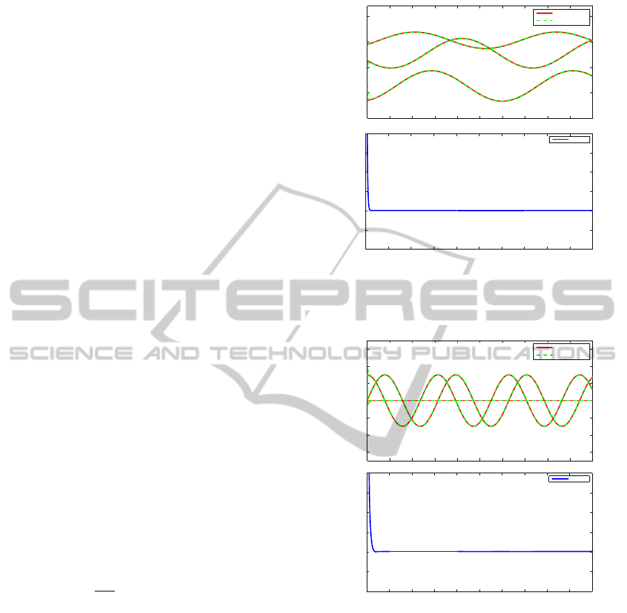
ence trajectory and the response are shown in Fig. 2
and Fig. 3.
The snapshots of 6 instances of the given task are
presented in Fig. 4.
0 1 2 3 4 5 6 7 8 9 10
−0.01
−0.005
0
0.005
0.01
0.015
0.02
Time[s]
Position error[m]
error
0 1 2 3 4 5 6 7 8 9 10
−2
−1.5
−1
−0.5
0
Position[m]
Reference
Response
Figure 2: Reference trajectory (solid lines) of the mobile
base movement and response(dashed lines) in the task of
the virtual robot, with position error.
0 1 2 3 4 5 6 7 8 9 10
−0.01
−0.005
0
0.005
0.01
0.015
0.02
Time[s]
Position error[m]
error
0 1 2 3 4 5 6 7 8 9 10
−0.6
−0.4
−0.2
0
0.2
0.4
0.6
Position[m]
Reference
Response
Figure 3: Reference trajectories (solid lines) and responses
(dashed lines) for the virtual mechanism task-space position
control in the task of winding the wool, with position error.
5 EXPERIMENTAL RESULTS
Experimental setup shown in Fig. 5 and Fig. 8 con-
sists of two 7 DOF Kuka LWR robot arms controlled
via Fast Research Interface (FRI). The experiments
were performed using the joint stiffness control mode
(Schreiber et al., 2010). The dynamic decoupling in
Kuka control unit (KRC) allowed us to use a simple
velocity control given by Eq. (28) where the weight-
ing matrix was W
W
W = I
I
I.
ICINCO2012-9thInternationalConferenceonInformaticsinControl,AutomationandRobotics
324
Figure 4: Simulation: winding the wool on a spool with a Kuka LWR arm and PA10 robot on a moving mobile robot Nomad,
6 consecutive instances.
Figure 5: Experimental setup with two Kuka LWR robot
arms for task of winding wool on a spool.
5.1 Experiment 1: Winding the Wool on
a Spool with the Dual-arm Kuka
LWR Robot
While performing the task of winding wool on a
spool, the first robot was pushed by a human. This
caused the increased torque in joints. When the torque
was above threshold value, the robot instantly became
compliant. After the perturbation, stiffness become
gradually high again.
This gradual change of the stiffness prevented the
movements of the robot. The impact of the perturba-
tion can be seen in Fig. 6.
5.2 Experiment 2: Cooperative Holding
of More Objects
The task of holding more objects together is a good
experiment to show the accuracy of the proposed al-
gorithm. The virtual mechanism task space was de-
fined with three translational coordinates in the frame
−0.5 −0.4 −0.3 −0.2 −0.1 0 0.1 0.2 0.3 0.4 0.5
−0.4
−0.3
−0.2
−0.1
0
0.1
0.2
0.3
0.4
x[m]
y[m]
Reference and response trajectory
Ref er ence
Response
Detail at [0.032, 0.298]
Figure 6: Reference trajectories (solid lines) and responses
(dashed lines) for the virtual mechanism task-space position
control. The detail show the effect of perturbations on the
trajectory.
0 5 10 15 20 25 30
−5
−4
−3
−2
−1
0
1
2
3
4
5
Time[s]
Trajectory error[mm]
error
Figure 7: Trajectory error between the reference and re-
sponse trajectory in the task of winding the wool.
T
0
and a linear movement along z-axis was applied
when grasping and dropping a group of seven objects.
No force control was used. After grasping the objects
together, some velocity perturbations were applied on
first four joints of the right robot arm to show the ac-
curacy of the grasp (objects should stay together). Ex-
VirtualMechanismApproachforDual-armManipulation
325
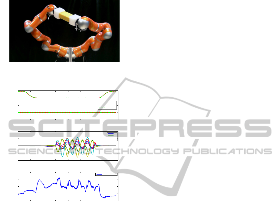
Figure 8: Experimental setup with two Kuka LWR robot
arms for task of holding of separate objects together.
0 5 10 15 20 25 30 35 40
−5
0
5
10
15
Time[s]
Force[N]
Measured external force on object
Externalf orce
0 5 10 15 20 25 30 35 40
−0.2
0
0.2
0.4
0.6
Distance[m]
Reference and response trajectory
Reference
Response
0 5 10 15 20 25 30 35 40
−20
−10
0
10
20
Velocity[rad/s]
Perturbations applied on right robot arm
˙q
1
˙q
2
˙q
3
˙q
4
Figure 9: Top: reference end response trajectories for grasp-
ing and releasing the objects. Middle: the velocity pertur-
bations applied on first four joints of right robot arm.
Bottom: the calculated external force applied on objects,
obtained from measurements at end-effector.
perimental results from the experiment are shown in
Fig. 9.
6 CONCLUSIONS
In this paper, we proposed a new control strategy for
cooperative manipulation. Our approach stated that
two robot arms holding the object, form a new aug-
mented kinematic chain. Object is presented as a vir-
tual mechanism with an arbitrary number of degrees
of freedom. Therefore, manipulating the object is ac-
complished by controlling the virtual mechanism.
Our algorithm also cope with the systems, where
one of cooperative manipulators base is moving. This
type of setup is very common in industry, where one
of the robots is mounted on a moving conveyoror mo-
bile robot, as shown in simulation.
REFERENCES
Caccavale, F., Chiacchio, P., and Chiaverini, S. (2000).
Task-space regulation of cooperative manipulators.
Automatica, 36(6):879–887.
Chiacchio, P. and Chiaverini, S. (1998). Complex robotic
systems. Springer-Verlag.
Khatib, O., Yokoi, K., Chang, K., Ruspini, D., Holmberg,
R., and Casal, A. (1996). Vehicle/arm coordination
and multiple mobile manipulator decentralized coop-
eration. In Intelligent Robots and Systems '96, IROS
96, Proceedings of the 1996 IEEE/RSJ International
Conference on, volume 2, pages 546 –553 vol.2.
Nemec, B. and
ˇ
Zlajpah, L. (2009). Contemporary Robotics,
Challenges and Solutions: Automatic Trajectory Gen-
eration using Redundancy Resolution Scheme Based
on Virtual Mechanism, pages 1–18. In-Teh.
Nemec, B.,
ˇ
Zlajpah, L., and Omrˇcen, D. (2007). Compar-
ison of null-space and minimal null-space control al-
gorithms. Robotica, 25(5):511–520.
Osumi, H. (1996). Cooperative strategy for multiple mo-
bile manipulators. In Intelligent Robots and Systems
'96, IROS 96, Proceedings of the 1996 IEEE/RSJ In-
ternational Conference on, volume 2, pages 554 –559
vol.2.
Schreiber, G., Stemmer, A., and Bischoff, R. (2010). The
fast research interface for the kuka lightweight robot.
In ICRA 2010 Workshop on Innovative Robot Con-
trol Architectures for Demanding (Research) Applica-
tions, pages 15–21.
Spong, M. W., Hutchinson, S., and Vidyasagar, M. (2005).
Robot Dynamics and Control: Velocity kinematics -
the manipulator Jacobian, pages 125–162. John Wi-
ley and Sons, Inc.
Uchiyama, M. and Dauchez, P. (1992). Symmetric kine-
matic formulation and non-master/slave coordinated
control of two-arm robots. Advanced Robotics,
7(4):361–383.
ICINCO2012-9thInternationalConferenceonInformaticsinControl,AutomationandRobotics
326
