
Consistency of UML Class and Statechart Diagrams
with State Invariants
Ali Hanzala Khan, Irum Rauf and Ivan Porres
Department of Information Technologies,
˚
Abo Akademi University,
˚
Abo, Finland
Keywords:
Model Consistency, Class Diagram, Statechart Diagram, State Invariants, OCL, Reasoning, OWL 2.
Abstract:
We present an approach and a tool to analyze the consistency of UML class and statechart diagrams containing
state invariants automatically. UML class diagrams describe the structure of a system as a collection of classes
while UML statechart diagrams describe its behavior. State invariants relate the active state configuration of
a statechart with object instances described in a class diagram. We consider a UML statechart inconsistent if
it contains unsatisfiable state invariants, that is, there are no object instances that can make a given invariant
evaluate to true. To detect such inconsistencies, we translate a UML model containing class and statechart
diagrams into the Web Ontology Language (OWL 2), and then use OWL 2 reasoning tools to infer the con-
sistency and satisfiability of the translated diagrams. The approach is supported by an automatic translation
tool and existing OWL 2 reasoners. We demonstrate our approach with an example design and evaluate its
performance using large UML models.
1 INTRODUCTION
The Unified Modeling Language (UML) is a widely
used modeling notation for documenting the design
of software intensive systems (OMG, 2011). A UML
model usually comprises a number of diagrams pro-
viding different views of a system. These diagrams al-
low us to decompose the design of a large system into
smaller and more manageable views. However, rep-
resenting a system as a collection of diagrams raises
the issue of possible design inconsistencies. In this
article we address the problem of the consistency of
UML class and statechart diagrams with state invari-
ants.
A class diagram describes the structure of a sys-
tem in the form of classes, their associations with each
other, the attributes of each class and operations that
can be invoked on them. On the other hand, a stat-
echart diagram provides the behavioral interface of a
class. It defines all possible sequences of method in-
vocations, the conditions under which methods can be
invoked and their expected results.
Each state in a statechart diagram represents a cer-
tain condition that is true when the state is active. The
condition can be implicit in the design, or defined ex-
plicitly in the form of a state invariant. A state invari-
ant is a boolean expression that is true when a given
state is active and false otherwise. State invariants are
defined using the attributes and associations described
in the class diagram and expressed using the Object
Constraint Language (OCL) (OMG, 2006).
Given a number of UML class and statechart dia-
grams, it is possible to specify unsatisfiable state in-
variants that describe states that can never be active
or operations that cannot be implemented according
to the well-formedness rules specified in the UML su-
perstructure specification (OMG, 2011). An unsatis-
fiable state invariant is considered inconsistent with
respect to a class diagram since there are no object in-
stances that can make an unsatisfiable invariant eval-
uate to true.
The inconsistent state invariants are design errors
and, in order to reduce development costs and time,
they must be detected and corrected as early in the
software development process as possible. The ap-
proach we propose to detect such inconsistencies is
based on the use of the automatic reasoning tools de-
veloped initially in the context of the semantic web.
We first translate the class and statechart diagrams
with state invariants in a UML model to the Web
Ontology Language version 2 for Description Logic
(OWL 2 DL) (W3C, 2009b), and then use an OWL 2
DL reasoning tool (Sirin et al., 2007; Shearer et al.,
2008; Tsarkov and Horrocks, 2006) to determine the
consistency of the UML design.
The approach presented here is limited to a frag-
14
Khan A., Rauf I. and Porres I..
Consistency of UML Class and Statechart Diagrams with State Invariants.
DOI: 10.5220/0004320100140024
In Proceedings of the 1st International Conference on Model-Driven Engineering and Software Development (MODELSWARD-2013), pages 14-24
ISBN: 978-989-8565-42-6
Copyright
c
2013 SCITEPRESS (Science and Technology Publications, Lda.)

ment of the OCL language, but on the other hand
is decidable and fully automatic. The designer does
not need to know the details of the translation or the
reasoning performed by the underlying tools. Also,
current reasoning tools and desktop computers can
process relatively large UML models in few seconds.
Therefore we consider that this approach has the po-
tential to be integrated with existing and future UML
tools and provide consistency analysis services that
go beyond what is being offered in current tools that
only use basic syntactic analysis and well-formed
rules.
This paper is organized as follows. In Section 2,
we present an overview of our approach with the help
of a running example and discuss the related work. In
Section 3, we discuss the problem and the proposed
solution for determining the consistency of a UML
model containing class and statechart diagrams. In
Section 4, we present the structure and the transla-
tions of class diagrams, statechart diagrams and state
invariants into OWL 2 DL. In Section 5, we discuss
about the implementation of the UML to OWL 2
translations in the form of a translation tool and the
consistency analysis by using OWL 2 reasoners. Fi-
nally, in Section 6, we conclude the paper.
2 CONSISTENCY OF CLASS AND
STATECHART DIAGRAM
In this section we present an overview of our approach
that we demonstrate with a running example and dis-
cuss previous work related to the consistency of UML
diagrams.
Our example system is a Content Management
System. In this system, authors post new articles to
be published after being reviewed by a reviewer. A
reviewer can accept, reject or advise a revision of the
paper. Only an accepted article can be published. An
article can be withdrawn if it is under review. How-
ever, a published article cannot be withdrawn. The
structure of this system is described as a UML class
diagram (Figure 1), while its behavior is described us-
ing a UML statechart diagram (Figure 2).
A statechart diagram defines behavior of a class in
terms of states that an instance of a class takes during
its lifecycle and the transitions between them. Each
transition from a source to a target state is triggered
by a function call.
The statechart diagram shown in Figure 2 defines
the behavioral view of the class Article of the class
diagram shown in Figure 1 in term of states. It con-
sists of one composite state ArticleReview and two
simple states Publish and ArticleWithdraw. The Ar-
Figure 1: The static view of Content Management System.
ticleReview composite state consists of four simple
states namely, WaitingforReview, Revisioning, Arti-
cleRejected and Accept. When the submit() method is
called on an object of the class Article, the statechart
diagram is initiated and the object enters into the state
WaitingforReview a substate of ArticleReview. The
method calls to accept(), reject() and revise() take the
object to the Accept, ArticleRejected and Revisioning
state respectively. When the author of the article is
revisioning the article, the object of the class Article
is in the Revisioning state. When the author revises
the article, he invokes the Revisioned() method of the
Article class and the object again comes into the Wait-
ingforReview state. The publish() method can be in-
voked from the Accept state and the object switched to
the Publish state. An article can be withdrawn by in-
voking the method withdraw() whenever the state Ar-
ticleReview is active, but the withdraw() method can-
not be invoked if the object of the class Article is in
the Publish state.
Each state in a statechart is annotated with a state
invariant. The state invariant is a boolean expression
that links classes of a class diagram to the states of a
statechart diagram. We say that an object of a class
is in a certain state if the state invariant of that state
is true. We express the state invariant of each state
by using OCL and annotate the behavioral diagram
of our example with state invariants in Figure 2. The
details about the OCL constructs used in our approach
will be discussed in Section 4.4.
We consider the state invariants which let the stat-
echart diagram behave against the UML superstruc-
ture specifications for statechart diagrams (OMG,
2011) as inconsistent state invariants, and may cause
whole system become unsatisfiable or inconsistent.
The examples of inconsistent state invariants are as
follows:
ConsistencyofUMLClassandStatechartDiagramswithStateInvariants
15
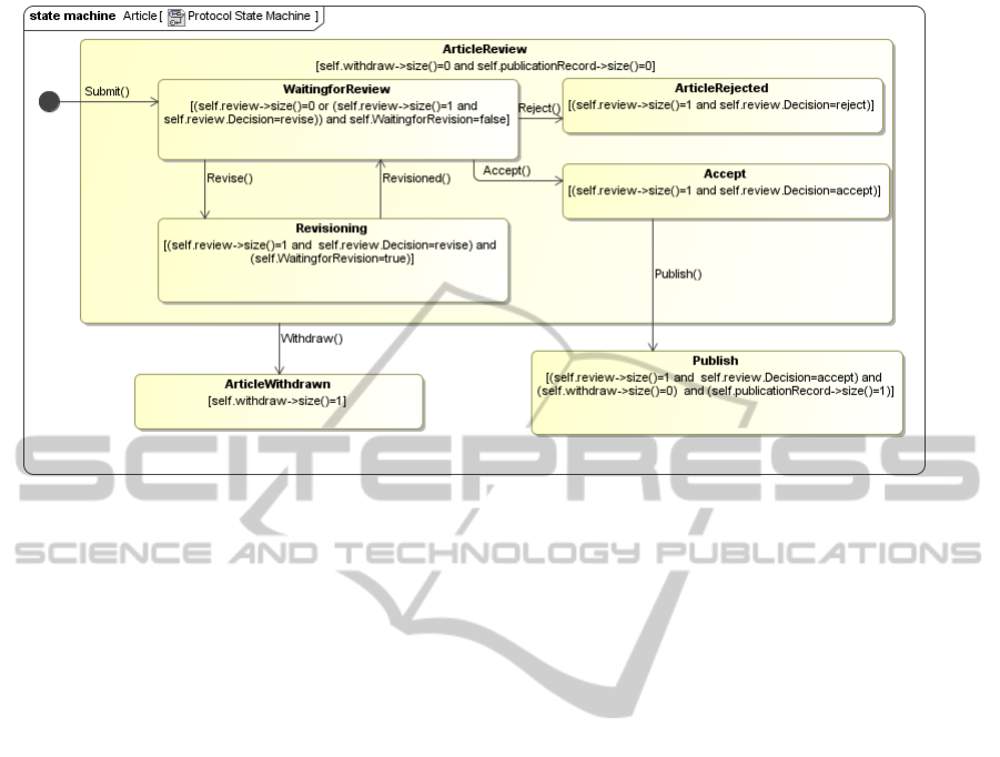
Figure 2: The behavioral view of the class Article of the class diagram shown in Figure 1.
Inconsistent State Invariant Example 1. Ac-
cording to the UML superstructure specification,
invariants of non-orthogonal states must be mutu-
ally exclusive ((OMG, 2011), p.564), for example
in the statechart diagram shown in Figure 2, the
article cannot be in the state of ArticleRe jected
if at the same time this article is in the state of
Accept. If we introduce an error by changing
the invariant value of the state ArticleRe jected to
self.review->size()=1 and self.review.Dec-
ision=accept, means that an article can be rejected
and accepted at the same time. The introduced
error allows an object of the class Article to be-
long to two non-orthogonal states i.e. Accept and
ArticleRe jected, which is the violation of the UML
superstructure specification of the statechart dia-
gram, and as a consequence the invariant of states
ActicleRe jected and Accept becomes inconsistent.
Inconsistent State Invariant Example 2. Accord-
ing to the UML superstructure specification, when-
ever a state is active, all its superstates are active
((OMG, 2011), p.565), means all invariants of an
active state and its superstates directly or transi-
tively are true. For example, in a statechart dia-
gram see Figure 2, if the state Accept is active then
its superstate ArticleReview should be also active.
If we introduce an error by adding the condition
self.withdraw->size()=1 in the invariant of the
state Accept, means that a withdrawn article can also
be accepted. The introduced error causes the contra-
diction between the invariants of the state Accept and
its superstate ArticleReview, and violates the UML
superstructure specification of the statechart diagram,
and consequently makes the invariant of the states
Accept, ArticleReview and ArticleWithdrawn incon-
sistent.
In the next section we discuss how we can carry
out the analysis of these kind of models using OWL 2
reasoning tools.
2.1 Previous Work
The consistency analysis of UML class diagrams and
statechart diagrams has been studied by a number of
researchers in the recent past, but often the analysis
has focused on different properties of a design. The
approach by Yeung et al. (Yeung, 2004) analyzes the
behavior of statecharts to find deadlocks, by translat-
ing class diagrams into the B-Method and statechart
diagrams into CSP. This approach is not focused on
the consistency of state invariants, the translation is
done manually and there is no discussion about the
verification method whether it is manual or automatic.
The approach by Rasch et al. (Rasch and
Wehrheim, 2003), uses Object-Z for the formaliza-
tion of class models and CSP for statechart diagrams,
this approach analyzes method invocations against the
class description and finds deadlocks by running the
class and statechart diagram formalization in FDR.
This approach is not focused on the analysis of the
consistency of state invariants. Furthermore, the ap-
proach by Lam et al. (Lam and Padget, 2005) ana-
lyzes the consistency of statechart diagrams and class
diagrams by using the π-calculus. The translation of
UML diagrams to π-calculus is done manually and
MODELSWARD2013-InternationalConferenceonModel-DrivenEngineeringandSoftwareDevelopment
16

the consistency is analyzed by running the π-calculus
script on the Workbench.
Moreover, the approach by Emil Sekerinski (Sek-
erinski, 2008) focus on the verification of statecharts.
In this approach, the events are manually translated
into generalized program statements, and these state-
ments appeared as the body of a transition. The exe-
cution of the program statements is based on the as-
sumption that the body of the transition can read or
write the values of the class variables.
The use of ontology languages and description
logic in the context of model validation has been
proposed in the past by different authors (Van
Der Straeten, 2005; Wang et al., 2006; Berardi et al.,
2005; Balaban and Maraee, 2008). However, to our
knowledge, none of them has addressed the reasoning
of the satisfiability of state invariants using OWL 2
DL. These works focus on the problem of class di-
agrams satisfiability, i.e., a class diagram can gener-
ate consistent object diagrams or not. Moreover, the
approach by Moaz et al. (Maoz et al., 2011), ana-
lyzes the consistency of class and object diagrams by
using Alloy. This is a fully automatic approach, in
this approach the class and object diagrams are first
translated into a parameterized Alloy module, and
then the consistency analysis is done by analyzing
the translated Alloy module by using the Alloy An-
alyzer. This approach do not yet supports statecharts
and OCL constraints. Furthermore, the TWOUSE ap-
proach (Walter et al., 2012) is focused on two areas,
first is the Ontology Development Modeling (ODM),
and the second is the translation and validation of Do-
main Specific Languages (DSL) by using OWL 2.
This approach proposes same methodology for the
validation of DSLs as presented in this article. How-
ever, their work on validation is limited to the valida-
tion of DSLs, and has not yet offered the validation of
statechart diagrams with or without state invariants.
Furthermore, Bogumila et al. (Hnatkowska et al.,
2001), analyze the consistency of the statechart dia-
gram of a class by writing OCL rules manually, and
then execute the OCL rules by using the OCL com-
piler. This approach is limited to analyzing consis-
tency of statechart diagrams against the class descrip-
tion and not using state invariants. In OCL, the model
validation rules must be defined explicitly based on
the syntax of the UML models. In our approach,
model validation is defined in the semantic interpre-
tation of the OCL and UML models. The differ-
ence is that while OCL must define a large number of
well-formed rules for different variations and combi-
nations of model elements, a logic approach requires
a smaller number of axioms that are often simpler.
To our knowledge, none of the above mention
work proposes an automatic translation and consis-
tency checking approach for UML class and stat-
echart diagrams with state invariants described in
OCL.
3 CONSISTENCY ANALYSIS
In this section we define the problem of determin-
ing the consistency of UML models containing class
and statechart diagrams as follows. Our view of
model consistency is inspired by the work of Broy
et al. (Broy et al., 2009). This work considers the
semantics of a UML diagram as their denotation in
terms of a so-called system model and defines a set of
diagrams as consistent when the intersection of their
semantic interpretation is nonempty.
In our work, we assume that there is a nonempty
set ∆ called the object domain containing all the pos-
sible objects in our domain. We propose that a UML
model depicting a number of class and statechart dia-
grams is interpreted as a number of subsets of ∆ rep-
resenting each class and each state in the model and
as a number of conditions that need to be satisfied by
these sets.
A UML class is represented a set C, such C ⊆ ∆.
An object o belongs to a UML class C iff o ∈ C. We
also represent each state S in a statechart as a subset
of our domain S ⊆ ∆. In this interpretation, the state
set S represents all the objects in the domain that have
such state active, that is, object o is in UML state S iff
o ∈ S.
Other elements that can appear in a UML model
such as generalization of classes, association of
classes, state hierarchy and state invariants are inter-
preted as additional conditions over the sets represent-
ing classes and states. For example class specializa-
tion is interpreted as a condition stating that the set
representing a subclass is a subset of the set repre-
senting its superclass. These conditions are described
in detail in the next section.
In this interpretation, the problem of a UML
model consistency is then reduced to the problem of
satisfiability of the conjunction of all the conditions
derived from the model. If such conditions cannot
be satisfied, then a UML model will describe one or
more UML classes that cannot be instantiated into ob-
jects or objects that cannot ever enter a UML state in a
statechart. This can be considered a design error, ex-
cept in the rare occasion that a designer is purposely
describing a system that cannot be realized. To ana-
lyze the UML models and discover possible inconsis-
tencies we will use the services of an OWL 2 reason-
ing tool, as described in the rest of this section.
ConsistencyofUMLClassandStatechartDiagramswithStateInvariants
17

3.1 Description Logic and OWL 2
The Description Logic used in our approach is classi-
fied as S R OI Q (Horrocks et al., 2006). Description
Logic is made up of concepts, denoted here by C, D,
and roles, denoted here by R,Q. A concept or role can
be named, also called atomic, or it can be composed
from other concepts and roles.
An interpretation I consists of a non-empty set
∆
I
and an interpretation function which assigns a set
C
I
⊆ ∆
I
to every named concept C and a binary rela-
tion R
I
⊆ ∆
I
× ∆
I
to every named role R.
The constructors of Description Logic are as fol-
lows:
Everything >
I
= ∆
I
Nothing ⊥
I
=
/
0
Complement (¬C)
I
= ∆
I
\C
I
Inverse (R
−
)
I
= {(y, x) | (x, y) ∈ R
I
}
Intersection (C u D)
I
= C
I
∩ D
I
Union (C t D)
I
= C
I
∪ D
I
Restriction
Universal (∀R.C)
I
= {x | ∀y.(x, y) ∈ R
I
→ y ∈ C
I
}
Existential (∃R.C)
I
= {x | ∃y.(x, y) ∈ R
I
∧ y ∈ C
I
}
Cardinality (≥ nR)
I
= {x | #{y | (x, y) ∈ R
I
} ≥ n}
(≤ n R)
I
= {x | #{y | (x, y) ∈ R
I
} ≤ n}
where #X is the cardinality of X. The axioms in DL
can be either inclusions C v D, C v D or equalities
C ≡ D, R ≡ Q.
An interpretation satisfies an inclusion C v D if
C
I
⊆ D
I
and an inclusion R v Q if R
I
⊆ Q
I
. An in-
terpretation satisfies an equality C ≡ D if C
I
= D
I
and
an equality R ≡ Q if R
I
= Q
I
. I satisfies a set of ax-
ioms if it satisfies each axiom individually – I is then
said to be a model of the set of axioms. Given a set
of axioms K , a named concept C is said to be satisfi-
able if there exists at least one model I of K in which
C
I
6=
/
0. A set of axioms is said to be satisfiable if all
of the named concepts that appear in the set are satis-
fiable. If a set of axioms K is satisfiable, we say that
an axiom φ is satisfiable with respect to K if K ∪{φ}
is satisfiable. Similarly, we say that φ is unsatisfiable
(w.r.t. K ) if K ∪ {φ} is unsatisfiable.
The decidability of SR OI Q is demonstrated by
Horrocks et al. (Horrocks et al., 2006).
3.2 OWL 2 Functional Syntax
For practical reasons, we use the OWL 2 functional
syntax (OWL2fs) (W3C, 2009b) as the language used
as an input for the reasoners and in the text of this
article. The interpretation of the main OWL 2 expres-
sions used in this article is presented in the follow-
ing table. A complete description of the OWL 2 se-
mantics, including support for data types can be found
in (W3C, 2009a).
SubClassOf(C D) C v D
EquivalentClasses(C D) C ≡ D
DisjointClasses(C D) C u D =
/
0
ObjectPropertyDomain(R C) ∀R
−1
.C
ObjectPropertyRange(R C) ∀R.C
ObjectMinCardinality( n R) ≥ nR
ObjectMaxCardinality( n R) ≤ nR
ObjectExactCardinality(n R) (≥ nR) u (≤ n R)
3.3 Reasoning
In order to determine the satisfiability of the concepts
represented in a UML model, we propose to represent
the UML model using a Description Logic, and ana-
lyze the satisfiability of the concepts using automated
reasoning tools. We have chosen OWL 2 DL to rep-
resent our UML models since we consider it is well
supported and adopted, and there exist several OWL 2
reasoners (Sirin et al., 2007; Shearer et al., 2008;
Tsarkov and Horrocks, 2006) for analyzing concept
satisfiability. A number of UML class diagrams, stat-
echart diagrams and state invariants are taken as an
input. All the inputs are translated to OWL 2 DL, and
then analyzed by a reasoner. The reasoner provides a
report of unsatisfiable and satisfiable concepts. Unsat-
isfiable concepts will reveal UML classes that cannot
be instantiated or UML states that cannot be entered.
In the next section, we discuss and translate the
structure of UML models with state invariants, and
the UML superstructure specification conditions over
the sets representing classes and states into OWL 2
DL.
4 FROM CLASS AND
STATECHART DIAGRAMS TO
OWL 2 DL
4.1 From Class Diagram to OWL 2 DL
According to the UML superstructure specification, a
UML class diagram is a set of classes and their rela-
tionships in form of associations and generalizations
((OMG, 2011), p.144). In order to analyze the consis-
tency of UML class diagrams, we need to first trans-
late all classes and their associations into OWL 2 on-
tology, and then validate the OWL 2 ontology using
an OWL 2 reasoner. In this section we only present
the translation of those class diagram concepts which
MODELSWARD2013-InternationalConferenceonModel-DrivenEngineeringandSoftwareDevelopment
18

are required for the validation of statechart diagrams
with state invariants such as: class, association, mul-
tiplicity, attributes and enumeration. All OWL 2 DL
translations we discuss in this section are based on
the Description Logic interpretation of UML concepts
given in (Van Der Straeten, 2005; Wang et al., 2006;
Maoz et al., 2011; Berardi et al., 2005; Balaban and
Maraee, 2008; Walter et al., 2012).
4.1.1 Class
A class in a class diagram represents a collection of
objects which share the same features, constraints and
definition. Each class in a class diagram is treated as
a class in OWL 2. A UML class C is translated in
OWL 2 as Declaration(Class(C)).
4.1.2 Objects Belong to a Class also Belong to its
Superclass
C2
C1
Class specialization is reduced to the
concept inclusion. We represent the
fact that a UML class C1 is a spe-
cialization of UML class C2 with the
condition C
1
v C
2
. In this case we
say that C2 is a superclass of C1. If C2 is a superclass
of C1 we say that they are in a specialization rela-
tion. The specialization relation C
1
v C
2
is translated
in OWL 2 as SubClassOf( C1 C2 ).
4.1.3 If an Object Belongs to Multiple Classes,
they are Related by Specialization
We assume that an object cannot belong to two dif-
ferent classes, except when these two classes are in a
specialization relation. In our semantic interpretation
of a UML class diagram, it is important to denote the
fact that two classes are not in a specialization rela-
tion.
We represent the fact that UML class C1 and UML
class C2 are not in a specialization relation with the
condition C
1
u C
2
=⊥. With this condition, an ob-
ject cannot belong to these two classes simultane-
ously. Due to the open-world assumption used in De-
scription Logic, we need to explicitly state this fact in
OWL 2 as DisjointClasses( C1 C2 ).
4.1.4 Association
We represent a UML directed binary association A
from class C1 to C2 as a relation A : C
1
xC
2
. An as-
sociation of a UML class in a class diagram is anno-
tated with a positive number; this number indicates
the multiplicity of an association. Association multi-
plicity describes a number of allowable objects of a
range class to link with the object of a domain class.
The multiplicity of an association defines additional
conditions over this relation #{y|(x, y) ∈ A} ≥ min,
#{y|(x, y) ∈ A} ≤ max.
C2
C1
min..max
A
A UML association A from
UML class C1 to C2 and have a
multiplicity (min, max) is repre-
sented in OWL 2 as:
Declaration(ObjectProperty(A))
ObjectPropertyDomain( A C1 )
ObjectPropertyRange( A C2 )
SubClassOf( C1
ObjectMinCardinality( min A ) )
SubClassOf( C1
ObjectMaxCardinality( max A ) )
4.1.5 Attributes
C
+Att1: Integer
+Att2: String
+Att3: Date
+Att4: Boolean
+Att4: Enum
Attributes containing data such as
integer or boolean are also repre-
sented as relations. In this case
the range of the relation A be-
longs to the set D represents the
datatype ∀x, y : (x, y) ∈ A =⇒ y ∈ D. Also, at-
tributes usually have a multiplicity restriction to one
value. The attributes of a UML class in a class dia-
gram are translated in OWL 2 as a DataProperty. In
OWL 2, the data property use datatype in its range.
The datatype can be xsd:boolean, xsd:string, xsd:int
and other datatypes see ((W3C, 2009b), Table 3). We
map attributes that use basic types by declaring a data
property with the attribute’s name. Also, an attribute
is a required component of its class. Consequently,
the data properties describing attributes have an ex-
act cardinality of one. The attribute Att of the UML
class C having any of the above mentioned DataType
is translated in OWL 2 as:
Declaration(DataProperty( Att ))
SubClassOf(C DataExactCardinality(1 Att ))
DataPropertyDomain( Att C )
DataPropertyRange( Att DataType )
4.1.6 Enumeration
«enumeration»
Enum
literal_1
..
literal_n
Enumeration is a kind of the
datatype, whose instances are
a user-defined enumeration
literals ((OMG, 2011), p.67).
The enumeration Enum is declared by using a
DatatypeDefinition axiom in OWL 2 DL. The
class attribute Att having a datatype Enum, means
∀x, y : (x, y) ∈ Att =⇒ y ∈ Enum where Enum is a
set of enumeration literals {(literal
1
), ...,(literal
n
)}
is represented in OWL 2 as:
ConsistencyofUMLClassandStatechartDiagramswithStateInvariants
19

DataPropertyRange(Att DataOneOf(
"literal1"ˆˆdatatype ..))
4.2 From Statechart Diagrams to
OWL 2 DL
A statechart diagram provides the behavioral interface
of a class and defines the sequence of method invoca-
tions, the conditions under which they can be invoked
and their expected results. In order to analyze the sat-
isfiability of state invariants in a statechart diagram,
we need to translate the states and their invariants into
OWL 2 DL. The translation of the state and the state
invariant includes the reference of the class and its at-
tributes. Therefore, we translate a statechart diagram
in the same ontology that contains the OWL 2 trans-
lation of a class diagram.
4.2.1 State and State Hierarchy
We represent a UML state as a concept represent-
ing the objects that have such state active. A con-
cept representing a state will be included in the con-
cept representing all object instances of the class as-
sociated to the statechart diagram, since all objects
that can have the state active belong to the given
class. That is, if the state S belongs to a statechart
diagram describing the behavior of the class C, then
S v C. We represent this in OWL 2 as follows:
S
sub
Declaration(Class(S))
SubClassOf( S C )
State hierarchy is also represented using a concept in-
clusion. Whenever a substate is active, its containing
state is also active. This implies that the concept rep-
resenting a substate will be included in the concept
representing is the parent state, sub v S. This is rep-
resented in OWL 2 as SubClassOf( sub S ).
4.2.2 Non-orthogonal States are Exclusive
S
S1 S2
The UML Superstructure
specification requires that if
a composite state is active
and not orthogonal, at most one of its substates is
active ((OMG, 2011), p.564). This means that an
object cannot be at the same time in the two concepts
representing two exclusive states, i.e., if S
1
and S
2
represents substates of an active and not orthogonal
composite state then S
1
u S
2
=⊥. When representing
a statechart diagram in OWL 2, the non-orthogonal
exclusive states are declared as disjoint, so that they
may not able to share any object.
DisjointClasses( S1..Sn )
4.2.3 Orthogonal States are Non-exclusive
S
R1 R2
S2S1
The UML Superstructure
specification requires that if
a composite state is active
and orthogonal, all of its regions are active ((OMG,
2011), p.564). That is if R
1
and R
2
are concepts rep-
resenting the two regions of an orthogonal composite
state represented by the concept S, then R
1
t R
2
= S.
We should note that if S
1
and S
2
represent two
substates where S
1
v R
1
and S
2
v R
2
, then they are
not exclusive and S
1
u S
2
6=⊥. Due to the open-world
assumption of DL, concepts may represent common
individuals unless they are explicitly declared as
disjoint.
4.3 State Invariant into OWL 2 DL
The UML specification defines a state in a UML
diagram as the representation of a specific con-
dition “A state models a situation during which
some (usually implicit) invariant condition holds”
((OMG, 2011), p.559-560). We understand from
this definition that the invariant condition charac-
terizes the state: if the invariant condition holds
the state is active, otherwise if the invariant con-
dition does not hold the state is not active.
S
Invariant
In our approach we represent
an invariant as an OWL 2 con-
cept representing objects that
make that invariant evaluate to true. Since the invari-
ant holds iff the associated state is active, the con-
cept representing a state will be the same as the con-
cept representing an invariant. This is represented in
OWL 2 as an equivalent class relation between the
state and its invariant:
EquivalentClasses (S Invariant)
Due to the equivalent relationship between the state
and its invariant, all objects that fulfill the condition
of its state invariant will also be in that specific state.
4.3.1 State Constraints
The UML also allows us to define additional con-
straints to a state, and names these constraints also
state invariants. However, the semantics of a state
constraint are more relaxed since it “specifies condi-
tions that are always true when this state is the current
state” ((OMG, 2011), p.562). In this sense, the state
constraints define necessary conditions for a state to
be active, but not sufficient. This means that, the ac-
tual state invariant may remain implicit. However, we
consider a state invariant as a predicate characterizing
MODELSWARD2013-InternationalConferenceonModel-DrivenEngineeringandSoftwareDevelopment
20

a state. That is, a state will be active if and only if its
state invariant holds.
4.3.2 A State Invariant Characterizes a State
The UML superstructure specification requires that
whenever a state is active its state invariant evaluates
to true ((OMG, 2011), p.562). A consequence of this
is that state invariants should be satisfiable. That is,
every state invariant in a statechart diagram must hold
in at least one object configuration. Otherwise there
cannot be objects that have such state active. Since
invariants should be satisfiable, the concept S repre-
senting a state should be satisfiable S 6=⊥.
4.4 OCL to OWL 2 DL
A state invariant is a runtime constraint on a state in
a statechart ((OMG, 2011), p.514). The UML speci-
fication proposes the use of OCL to define constraints
in UML models, including state invariants. OCL is
well supported by many modeling tools (Birgit De-
muth, 2009; Garcia and Shidqie, 2007). Unfortu-
nately, in general OCL is not decidable. However, we
can avoid undecidability by restricting our approach
to a reduced fragment of the full OCL (Queralt et al.,
2012a). The use of a limited fragment of OCL to
avoid undecidability has been proposed in the past
also by other authors (Queralt et al., 2012a; Queralt
et al., 2012b).
In this article, we consider OCL constructs using
mainly multiplicity, attributes value and boolean op-
erators. The grammar of OCL, supported in our ap-
proach is shown in Figure 3.
4.4.1 Attribute Constraints
State
{self.Att=Value}
The value of the attribute is
accessed in OCL by using a
keyword sel f or by using a
class reference ((OMG, 2006), p.15), the value
constraint of the attribute Att is written in OCL
as self.Att=Value, meaning {x|(x,Value) ∈ Att},
where Value represents the attribute value. The re-
striction on the value of the attribute is translated in
OWL 2 by using the axiom DataHasValue. The OCL
attribute value constraint self.Att=Value is trans-
lated in OWL 2 as:
DataHasValue(Att "Value"ˆˆdatatype )
In above translation, Att is the name of the attribute,
Value is the value of the attribute and it is always writ-
ten in OWL 2 in double quotes, and datatype is the
datatype of the attribute Value.
4.4.2 Multiplicity Constraints
State
{self.A-->size()=Value}
The multiplicity of an as-
sociation is accessed by us-
ing size() operation in OCL
((OMG, 2006), p.144). The multiplicity con-
straint on the association A in OCL is written as
self.A->size()=Value, where Value is a posi-
tive integer and represents a number of allowable in-
stances of the range class of the association A. We can
use a number of value restriction infix operators with
size() operation such as =, >=, <=, < and >. The
multiplicity constraint on an association A is defined
as {x|#{y|(x, y) ∈ A}OP Value}, where OP is the infix
operator and Value is a positive integer. The transla-
tion of size() operation in OWL 2 is based on the in-
fix operator used with the size() operation, for exam-
ple, the OCL constraint self.A->size()=Value, in
which A is the name of an association, ”>” is an infix
operator and Value is a positive integer, translated in
OWL 2 as: ObjectExactCardinality(Value A).
Furthermore, the constructs isEmpty and
notEmpty represent size() = 0 and size() > 0 re-
spectively. The invariant self.A->isEmpty() is
translated in OWL 2 as:
ObjectExactCardinality(0 A)
and the invariant self.A->notEmpty() is translated
in OWL 2 as:
ObjectMinCardinality(1 A)
4.4.3 Boolean Operators
State
{self.Att=Value and
self.A->size()=Value}
The constraints in a state in-
variant are written in a form
of a boolean expression, and
joined by using the boolean operators, such as ”and”
and ”or” ((OMG, 2006), p.144). The binary ”and”
operator evaluates to true when both boolean ex-
pressions Ex
1
and Ex
2
are true. In our transla-
tion this is represented by the intersection of the
concepts that represent both expressions Ex
1
∩ Ex
2
as ObjectIntersectionOf(Ex1 Ex2). The binary
”or” operator evaluates to true when at least one of the
boolean expression Ex
1
or Ex
2
is true. In our trans-
lation this is represented by the union of the concepts
that represent both expressions Ex
1
tEx
2
. This is rep-
resented OWL 2 as ObjectUniounOf(Ex1 Ex2).
ConsistencyofUMLClassandStatechartDiagramswithStateInvariants
21

hOCL-expressioni ::= hcond-expri (hlogic-opihcond-expri)
∗
hlogic-opi ::= and | or
hcond-expri ::= hrefi →size()hrelational-operatorihinteger-literali
| hrefi →isEmpty() | hrefi → notEmpty()
| hrefihrelational-operatorihprimitive-literali
hrefi ::= self.hidentifieri
hidentifieri ::=
0
{hcharactersi} | 0..9 {0..9}
0
hrelational-operatori ::= < | <= | > | >= | <> | =
hprimitive-literali ::= hboolean-literali | hinteger-literali
| hstring-literali | null
hboolean-literali ::= true | false
hinteger-literali ::= 0..9 {0..9}
hstring-literali ::=
0
{hcharactersi}
0
Figure 3: The grammar of the supported OCL fragment.
// Class Diagram into OWL 2 DL
Declaration(Class(Article))
Declaration(Class(Review))
Declaration(Class(Withdraw))
Declaration(Class(PublicationRecord))
...
DisjointClasses( Article Review ...)
Declaration(ObjectProperty(review))
ObjectPropertyDomain( review Article)
ObjectPropertyRange( review Review )
...
SubClassOf( Article
ObjectMaxCardinality( 1 review ))
....
Declaration(
DataProperty( WaitingforRevision))
SubClassOf(Article
DataExactCardinality(1 WaitingforRevision))
...
DataPropertyDomain(
WaitingforRevision Article )
..
DataPropertyRange(
WaitingforRevision xsd:boolean )
//Statechart diagram into OWL 2 DL
Declaration(Class(ArticleReview))
Declaration(Class(ArticleWithdraw))
Declaration(Class(Publish))
SubClassOf( ArticleReview Article )
SubClassOf( ArticleWithdraw Article )
SubClassOf( Publish Article ))
...
DisjointClasses( ArticleReview
ArticleWithdraw Publish )
Declaration(Class(WaitingforReview))
SubClassOf( WaitingforReview ArticleReview )
...
//Invariant of state Publish Start
EquivalentClasses (Publish
ObjectIntersectionOf(
ObjectIntersectionOf(
ObjectExactCardinality(1 review)
DataHasValue(Decision "accept"ˆˆxsd:string ))
ObjectIntersectionOf ( ObjectExactCardinality
(0 withdraw) ObjectExactCardinality
(1 publicationRecord)) ) )
//Invariant of state Publish End
Figure 4: The excerpt of the output ontology generated by the translation tool.
5 CONSISTENCY ANALYSIS
USING AN OWL 2 REASONING
TOOL
We have defined earlier the satisfiability of UML
models in Section 3. The consistency analysis of
UML models is reduced to the satisfiability of the
conjunction of all conditions derived from a model.
In order to determine the satisfiability of the condi-
tions represented in UML models, we first translate
the UML models into an OWL 2 ontology, then use an
OWL 2 reasoner to analyze the satisfiability of trans-
lated concepts.
To translate UML models into OWL 2 ontology,
we have implemented the translations of class dia-
grams, statechart diagrams and state invariants dis-
cussed in Section 4, in an automatic model to text
transformation tool. The implemented translation
tool allows us to automatically translate class dia-
grams, statechart diagrams and state invariants into
OWL 2 DL. The translator reads class diagrams, stat-
echart diagrams and OCL state invariants from an in-
put model serialized using the XMI format. The XMI
MODELSWARD2013-InternationalConferenceonModel-DrivenEngineeringandSoftwareDevelopment
22

Found 4 unsatisfiable concept(s):
a:Accept
a:ArticleRejected
a:ArticleReview
a:ArticleWithdrawn
Figure 5: The satisfiability report of the ontology shown in
Figure 4 generated by the OWL 2 reasoner Pellet.
is generated by using a modeling tool. We used Mag-
icdraw to create the example designs used in this arti-
cle. The output of the translation tool is an ontology
file ready to be processed by an OWL 2 reasoner.
As an example, we have translated the class di-
agram, statechart diagram and OCL state invariants
shown in Figure 1 and Figure 2, into OWL 2 DL on-
tology using the implemented translation tool. An ex-
cerpt of the output ontology generated by the transla-
tion tool is shown in Figure 4.
5.1 Reasoning
After translating the class diagram, statechart diagram
and state invariants into an OWL 2 ontology by us-
ing the implemented translation tool, we process the
ontology by using an OWL 2 reasoner. The OWL 2
reasoner combines all the facts presented as axioms
in the ontology and infers logical consequences from
them. When we give the generated ontology to the
reasoner, it generates a satisfiability report indicat-
ing which concepts are satisfiable and which not. If
the ontology has one or more unsatisfiable concept,
this means that the instance of any unsatisfiable con-
cept will make the whole ontology inconsistent, con-
sequently, an instance of the class describing an un-
satisfiable concept in a class diagram will not exist, or
objects will not enter into a state describing an unsat-
isfiable condition, otherwise viceversa.
In order to analyze the satisfiability of the incon-
sistent invariants listed in Section 2. The ontology of
an example model with inconsistent invariants is vali-
dated by using an OWL 2 reasoner name Pellet (Sirin
et al., 2007). The satisfiability report of the ontology
of UML models with inconsistent state invariants is
shown in Figure 5. As explained in Section 4.3, a
state invariant characterizes the state ((OMG, 2011),
p.559-560). Therefore, the presence of unsatisfiable
states in the satisfiability report indicates the existence
of inconsistent state invariants in identified states.
5.2 Performance Analysis
In order to determine the performance of the transla-
tion and reasoning tools, we conducted an experiment
Figure 6: The graph of the total time (Translation time +
Reasoning time) to process valid and mutated models.
using UML class and statechart diagrams consisting
of 10 to 2000 model elements. We use a desktop com-
puter with an Intel Core 2 Duo E8500 processor run-
ning at 3.16GHz with 2GB of RAM. The performance
tests are conducted for both consistent and mutated
models containing inconsistencies introduced by us.
For each test, we measure the time required to trans-
late a model from UML to OWL 2 and the time re-
quired by the OWL 2 reasoners Pellet (Sirin et al.,
2007) and HermiT (Shearer et al., 2008) to analyze
the models. The results are shown in Table 1, and in
Figure 6.
Table 1: Time taken by the translation tool and rea-
soning engines to process UML models.
Model El-
ements
10 100 500 1000 1500 2000
Translation
Time
0.08s 0.11s 0.19s 0.30s 0.44s 0.53s
Pellet
Valid 2.2s 2.3s 2.6s 3.2s 3.6s 3.8s
Mutated 2.2s 2.4s 2.7s 3.2s 3.6s 3.9s
HermiT
Valid 0.6s 0.7s 1.2s 1.7s 2.2s 2.6s
Mutated 0.7s 0.7s 1.3s 1.8s 2.3s 2.6s
The time complexity of OWL 2 DL with respect
to the reasoning problems of the ontology consistency
and instance analyzing is NEXPTIME complete (Hor-
rocks et al., 2003). However, the graph (Figure 6) of
the performance test shows that the time required to
reason about models only grows linearly. This is due
to the fact that in our approach we analyze the con-
sistency of class and statechart diagrams without in-
dividuals.
6 CONCLUSIONS
In this article we have presented an approach to an-
ConsistencyofUMLClassandStatechartDiagramswithStateInvariants
23

alyze the consistency of UML class diagrams and
UML statechart diagrams with state invariants. The
approach is fully automated thanks to the translation
tool and the existing OWL 2 reasoners. Since the
translation tool accepts standard UML models seri-
alized using the XMI standard, the approach can be
easily integrated with existing UML modeling tools.
Our approach is decidable because we restrict our-
selves to an admittedly small fragment of OCL. This
strategy has been already used for expressing con-
straints over class diagrams (Cabot et al., 2008; Quer-
alt et al., 2012b). We believe that the use of limited
subsets of OCL do not reduce the merits of this and
similar approaches even if they cannot be used to pro-
cess all possible OCL constraints. An analysis tool
could in fact integrate different analysis approaches
and use the right one depending of the fragment of
OCL used in the models.
The performance experiments show that the pro-
posed approach can process relatively large UML
models in few seconds by using current reasoning
tools on desktop computers. Therefore, we consider
that this approach has the potential to be incorporated
with existing and future UML modeling tools and of-
fer consistency analysis services that go ahead of what
is being offered in current modeling tools.
REFERENCES
Balaban, M. and Maraee, A. (2008). A UML-based method
for deciding finite satisfiability in description logics.
In Description Logics.
Berardi, D., Calvanese, D., and Giacomo, G. D. (2005).
Reasoning on UML class diagrams. Artif. Intell.,
168(1-2):70–118.
Birgit Demuth, C. W. (2009). Model and Object Verifi-
cation by Using Dresden OCL. In Proceedings of
the Russian-German Workshop Innovation Informa-
tion Technologies: Theory and Practice,, pages 81–
89.
Broy, M., Cengarle, M. V., Gr
¨
onniger, H., and Rumpe, B.
(2009). Considerations and Rationale for a UML Sys-
tem Model. In UML 2 Semantics and Applications,
pages 43–60. John Wiley & Sons, Hoboken.
Cabot, J., Clariso, R., and Riera, D. (2008). Verification of
UML OCL class diagrams using constraint program-
ming. ICSTW, pages 73–80.
Garcia, M. and Shidqie, A. J. (2007). OCL Compiler for
EMF. In Eclipse Modeling Symposium at Eclipse
Summit Europe 2007, Stuttgart, Germany.
Hnatkowska, B., Huzar, Z., and Magott, J. (2001). Consis-
tency Checking in UML Models. In ISM’01.
Horrocks, I., Kutz, O., and Sattler, U. (2006). The even
more irresistible SROIQ. In KR, pages 57–67.
Horrocks, I., Peter, F., Schneider, P., and Harmelen, F. V.
(2003). From SH I Q and RDF to OWL: The mak-
ing of a web ontology language. J. of Web Semantics,
1(1):7–26.
Lam, V. S. W. and Padget, J. A. (2005). Consistency check-
ing of statechart diagrams of a class hierarchy. In
ECOOP, pages 412–427.
Maoz, S., Ringert, J. O., and Rumpe, B. (2011). Seman-
tically configurable consistency analysis for class and
object diagrams. In MoDELS, pages 153–167.
OMG (2006). OCL, OMG Available Specification, Version
2.0. http://www.omg.org/spec/OCL/2.0/.
OMG (2011). UML, Superstructure Specification, Ver-
sion 2.4.1. http://www.omg.org/spec/UML/2.4.1/
Superstructure/.
Queralt, A., Artale, A., Calvanese, D., and Teniente, E.
(2012a). OCL-Lite: A decidable (yet expressive)
fragment of OCL. In Proc. of the 25th Int. Work-
shop on Description Logics (DL 2012), volume 846 of
CEUR Electronic Workshop Proceedings, http://ceur-
ws.org/, pages 312–322.
Queralt, A., Artale, A., Calvanese, D., and Teniente, E.
(2012b). OCL-Lite: Finite Reasoning on UML/OCL
Conceptual Schemas. Data and Knowledge Engineer-
ing, 73:1–22.
Rasch, H. and Wehrheim, H. (2003). Checking consis-
tency in uml diagrams: Classes and state machines. In
FMOODS 2003, volume 2884 of LNCS, pages 229–
243. Springer Berlin / Heidelberg.
Sekerinski, E. (2008). Verifying statecharts with state in-
variants. In ICECCS, pages 7–14.
Shearer, R., Motik, B., and Horrocks, I. (2008). HermiT: a
highly-efficient OWL reasoner. OWLED.
Sirin, E., Parsia, B., Grau, B. C., Kalyanpur, A., and Katz,
Y. (2007). Pellet: A practical OWL-DL reasoner.
Journal of Web Semantics, 5:51–53.
Tsarkov, D. and Horrocks, I. (2006). Fact++ description
logic reasoner: system description. In Proceedings of
the Third international joint conference on Automated
Reasoning, IJCAR’06, pages 292–297, Berlin, Hei-
delberg. Springer-Verlag.
Van Der Straeten, R. (2005). Inconsistency Management
in Model-driven Engineering. An Approach using De-
scription Logics. PhD thesis, Vrije Universiteit Brus-
sel, Brussels, Belgium.
W3C (2009a). OWL 2 Web Ontology Language Di-
rect Semantics. http://www.w3.org/TR/owl2-direct-
semantics/.
W3C (2009b). OWL 2 Web Ontology Language
Structural Specification and Functional-Style Syn-
tax. http://www.w3.org/TR/2009/REC-owl2-syntax-
20091027/.
Walter, T., Parreiras, F., and Staab, S. (2012). An ontology-
based framework for domain-specific modeling. Soft-
ware and Systems Modeling, pages 1–26.
Wang, S., Jin, L., and Jin, C. (2006). Ontology definition
metamodel based consistency checking of UML mod-
els. In CSCWD 2006, pages 1–5.
Yeung, W. L. (2004). Checking Consistency between UML
Class and State Models Based on CSP and B. J. UCS,
10(11):1540–1559.
MODELSWARD2013-InternationalConferenceonModel-DrivenEngineeringandSoftwareDevelopment
24
