SafeNet of Unsafe Devices
Extending the Robot Safety in Collaborative Workspaces
Federico Vicentini, Nicola Pedrocchi and Lorenzo Molinari Tosatti
Institute of Industrial Technologies and Automation (ITIA), National Research Council (CNR), via Bassini 15 Milan, Italy
Keywords:
Safety, Industrial Robots, Network Controlled System, System Engineering, Functional Safety, ISO 13489,
ISO 10218.
Abstract:
Collaborative workspaces represent the benchmark scenario of contemporary and future industrial robotics,
where hybrid production systems and multimodal interactions among human operators and robots in coopera-
tive tasks can foster the flexibility of robotic systems. Physical interactions together with dynamic workspace-
sharing represent some reference applications in ISO 10218-2, where restrictive conditions for safety are posed
at system level, eventually limiting the robot execution speed. With the aim of extending the use of industrial
robots in shared environments and allowing the use of generically unsafe sensory and computational com-
ponents for advanced applications, a methodology called SafeNet is presented. It considers the system as a
device at large and applies the concept of functional safety (ISO 13489-1) with a set of architectural procedures
and implementations. The safety aspects of structure, reliability and monitoring are addressed by a redundant
system of computational nodes distributed over a network. SafeNet systems can be upgraded to candidate for
safe Performance Levels.
1 INTRODUCTION
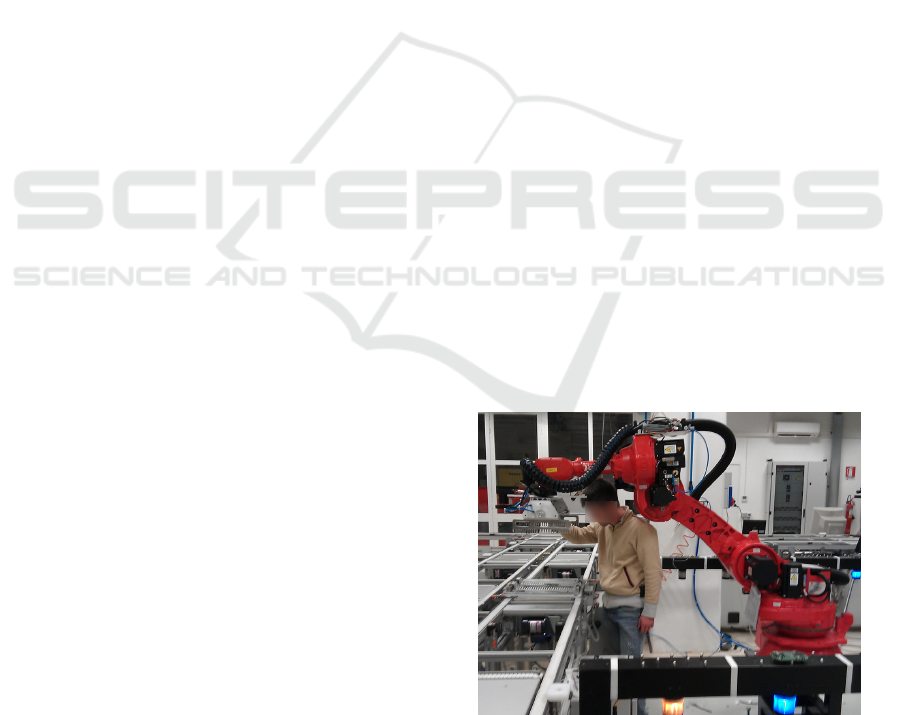
Collaborative workspaces (Fig. 1) are widely reck-
oned by both the industrial and the academic commu-
nities as one of the elective scenarios for the present-
day industrial robotics. Safety, specifically, is one of
the predominant functional aspects at both machine
and system levels. Under this perspective, robots,
as stand-alone machines, benefit from several tech-
nologies designed for a transparent and safe physical
Human-Robot Interaction (pHRI) (De Santis et al.,
2008; Alami et al., 2006). Such technologies sup-
port entirely new benchmarks for service robotics, as
well as for many industrial applications. Examples in-
clude compliant actuation systems (Grebenstein et al.,
2012; Bicchi et al., 2008; Zinn et al., 2004; Pratt and
Williamson, 1995) and lightweight platforms (Kock
et al., 2011; Albu-Sch
¨
affer et al., 2007a) that feature
compliant behavior attained by mechanics and con-
trol (Albu-Sch
¨
affer et al., 2007b) and that display lim-
ited energy transfer in impacts (Haddadin et al., 2008;
Haddadin et al., 2009). Together with internal or add-
on sensing, e.g. tactile skins (Vogel et al., 2011),
such compliant platforms represent a class of elec-
tive devices for shared environments. In such a con-
text, safety issues are predominantly treated in terms
Figure 1: Paradigmatic scenario of a collaborative
workspace for an industrial robot cell without fences.
of hazardous impacts or energy transfer, whose mag-
nitudes and way of assessing are under discussion in
ISO/TS 15066 (ISO, 2011c).
Physical HRI, however, is only a form of collabo-
ration in shared workspaces. Paradigmatic workflows
may, in fact, involve a mix of hand-guided proce-
dures and contactless co-presence in the same safe-
guarded space. Such scenarios are particularly rele-
vant for industrial robots, which as stand-alone de-
vices have to comply with eventual stops or speed
276
Vicentini F., Pedrocchi N. and Molinari Tosatti L..
SafeNet of Unsafe Devices - Extending the Robot Safety in Collaborative Workspaces.
DOI: 10.5220/0004479502760283
In Proceedings of the 10th International Conference on Informatics in Control, Automation and Robotics (ICINCO-2013), pages 276-283
ISBN: 978-989-8565-71-6
Copyright
c
2013 SCITEPRESS (Science and Technology Publications, Lda.)
a b c
d e
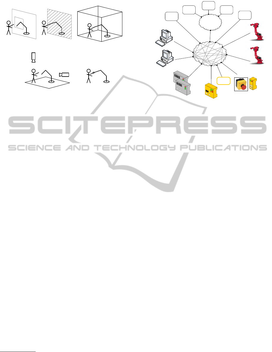
Figure 2: Classes of cooperative tasks as in ISO 10218-
2:2011 Annex E (graphics copyright by ISO International
Organisation for Standardisation): a) hand-over window, b)
interface window, c) inspection, d) collaborative workspace,
e) hand-guided robot.
limitations in such safeguarded spaces, as required
by ISO 10218-1 (ISO, 2011a). Many optional safety
packages in commercial controllers (KUKA Roboter,
2012; ABB Robotics, 2008) are, in fact, available for
joints position safe checks at runtime, providing the
basic information for a safe assessment of the robot
configuration within a safeguarded space. This, in
turn, represents the necessary condition for integrat-
ing safe application modes (Fig. 2) in dynamically
shared environments as in ISO 10218-2 (ISO, 2011b).
Nevertheless, robots and robot systems, compul-
sorily featuring speed limitations in the safeguarded
workspace (normative status quo), may conversely
need higher task speeds and, additionally, may require
the use of pervasive sensing and context awareness.
This monitoring capability almost always needs dis-
tributed sensor equipments dedicated to the detection
of the environment and users. Sensor processing and
interpretation could, in turn, require significant com-
putational power, so that collaborative workspaces
would be, in a general sense, portrayed as distributed
robotic systems
1
(Fig. 3). The resulting paradigmatic
architecture is therefore a network of general-purpose
devices, notably including unsafe nodes and where
safe/unsafe controllers are parts of a wider set of data
producers/consumers.
In this paper we discuss a methodology developed
in fact to fullfil ISO 10218-2 safety requirements for
a robotic system with unsafe nodes (robots included)
through a set of architectural and procedural actions
over the system. The two key concepts are that (i)
1
specifically Network Controlled Systems (Gupta and
Chow, 2010; Hespanha et al., 2007), when control actions
proper are distributed among several nodes .
sensors
sub-network
unsafe
sensor
robot control
unsafe
sensor
safe PLC
unsafe
PLCs
unsafe PCs
(soft real time)
unsafe PCs
(hard real time)
safe
sensor
safe I/O
robot control
unsafe
sensor
unsafe
sensor
unsafe
sensor
network
Figure 3: A robotic distributed system including both safe
and unsafe nodes/devices.
the system at hand can be seen as a single (complex)
device that (ii) has to display functional safety as a
whole. Functional safety is the “part of safety relating
to the Equipment Under Control (EUC) and the EUC
control system that depends on the correct function-
ing of the Electric/Electronic/Programmable Elec-
tronic (E/E/PE) safety-related systems, other technol-
ogy safety-related systems and external risk reduction
facilities” (IEC, 2010). Since the system at hand can
be considered a single EUC when used for interacting
with and monitoring the collaborative workspace, it
is required to be validated with respect to functional
safety criteria as in ISO 13489-1 (ISO, 2006). Equiv-
alently, components in a system are not required to
be safe per se but, rather, the system functional safety
depends on to which extent the residual probabilities
of failures in exchanged data can be limited.
The core methodology here discussed aims at ex-
tending the functional safety of data flows before any
usage of such data in the network. Applications even-
tually using such safe data in safety functions do not
contribute to the preliminary safe assessment of data.
Rather, being the way the nodes are safely checked
relevant for the overall risk assessment, such net-
work can freely integrate both safe and un-safe sen-
sors/devices. This would make the exclusive use of
individually safety-rated devices non-necessary for a
safe system integration. A relative freedom in the
integration of subsystems, remarkably computational
nodes in PC-based robotic applications, is considered
to be beneficial for the evolution of industrial robotic
cells towards fully-collaborative fully-open environ-
ments. Such freedom of components choice, some-
times actually being the only choice because of re-
quired specific technologies that are not supported by
safety-rated devices, reflects the concept of extension
SafeNetofUnsafeDevices-ExtendingtheRobotSafetyinCollaborativeWorkspaces
277
senso
r
sensor
sensorrobot
robot(s) sensor(s)
network
create and check
redundancy
check
consistency
architectural
and
procedural
actions
senso
r
sensor
sensorrobot
robot(s) sensor(s)
network
data usage
(e.g. avoid collisions)
FB FB
safe data usage (safety functions)
robot
functionally
safe
sensor
(applications)
redundant
sources
evaluation
procedural redundancy
check
node 1
check
node 2
unsafe
consistency
check
architectural redundancy
FB
FB
safe node
(a) (b)
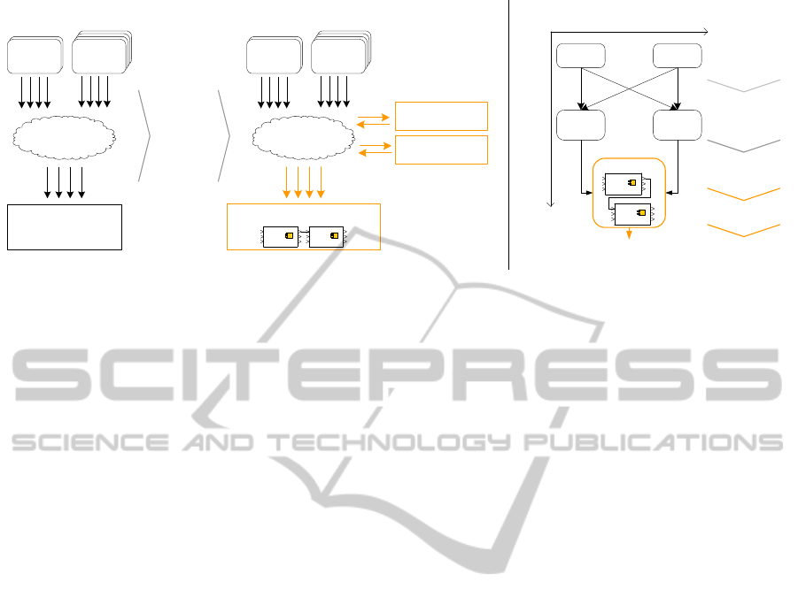
Figure 4: Methodological framework for a SafeNet: in (a) a common network of mixed safe/unsafe devices turns into a
safe network through a set of architectural and procedural actions, i.e. involving redundancy and consistency check over the
network, making the following usage of data functionally safe. Such actions are detailed in (b) where different sources (robots
and sensors) are procedurally evaluated in two (architecturally redundant) check nodes. Upon data procedural evaluation, data
consistency between the two nodes is verified by a safe node/layer through safety functions (FB), then used.
of safety features in networks rather than restricting
the usage of few rated protocols, as reckoned in the
progressive introduction/standardization of safe pro-
tocols into the main families of automation fieldbuses
(Moyne and Tilbury, 2007; Decotignie, 2005; Felser,
2005).
On top of the methodology here discussed, the
system integration has nevertheless to provide a gen-
eral assessment, evaluation and mitigation of risks ac-
cording to ISO 12100 (ISO, 2010) wrapping guide-
lines, which are out of scope in this work. In the next
section, instead, the procedural and architectural as-
pects of the extension of safety to data flows are dis-
cussed.
2 SAFENET FRAMEWORK
Functional safety is a key element of system design
based on (i) well-tried components and methods and
on (ii) the application of the principles of redundancy,
diversity, monitoring. Functional safety is expressed
as a ISO 13489-1:2006 Performance Level (PL), or
equivalent IEC 61508 SIL level, which encapsulate
the rate of reliability, failure-detectability and ready-
ness to recovery of a component/system. Specifically
for a robotic system, the required safety-rate is (ISO,
2011b):
(
PL
r
= d i.e. PFH
d
∈ [10
−7
,10
6
)
Cat.3 Designated Architecture
where PL
r
is the required performance level, PFH
d
is the Probability of dangerous Failures per Hour and
Cat.3 is one of the two safest ISO 13489-1:2006 cat-
egories of Safety Related Parts of a Control System
(SRP/CS) using double channels (see details in sec-
tion 2.2). Such functional safety rate is the aim of
the actions (Fig. 4-a) that transform a network of un-
safe devices in a SafeNet and that mainly involve a
double set of data validation and cross-checking. The
purpose is to reduce the probability of failing in de-
tecting occasional inconsistencies in data processed
by different nodes. Distributed systems, in particu-
lar, are likely to include sensors used for environmen-
tal monitoring that are eventually available for track-
ing the robot(s) motion inside a shared workspace as
well. The possible configurations of sensors and con-
trollers are very diverse, only optionally including na-
tive safety packages in robot control. External motion
tracking information are, instead, rarely matching the
safety-rate standards.
The above listed principles of redundancy, diver-
sity and monitoring are therefore applied to the ver-
ification of such tracking information by a double
independent elaboration of a single target informa-
tion, obtained along both a procedural and an archi-
tectural dimension (Fig. 4-b). The procedural redun-
dancy corresponds to the plain use of data from both
the tracked (unsafe) robot and the tracking unsafe sen-
sors, verifying that values match within given toler-
ances. The architectural redundancy, complementar-
ily, is obtained distributing robots and sensors data in
doubled flows for independent procedural evaluation.
Then, both comparative units (check nodes) are veri-
fied for consistency by a final safe unit/layer, i.e. data
are fed to safety functions coded according to IEC
ICINCO2013-10thInternationalConferenceonInformaticsinControl,AutomationandRobotics
278

Figure 5: Threshold inaccuracy ε in motion tracking due to
speed v and time latency τ.
61131-3/61508 in natively safety-rated logic devices
or mapped in safe I/Os distributed over safe protocols.
Such final step is compactly represented in Fig. 4-b
by a safe node that acts as the safety gate between the
safety functions domain and all the general purpose
CPUs or unsafe sensors.
As a result, such architecture is equivalent to a
SRP/CS distributed in two components and a safe
node, suitable to fulfill the preliminary conditions for
a PL d implementation, i.e. the dual structure and the
availability of monitoring coverage.
Proceeding with the tracking configuration, the
procedural and architectural aspects of the SRP/CS
are discussed in the following subsections: robots and
sensors data-check (procedure, Section 2.1) mainly
involve kinematic and accuracy considerations, while
the data-flows dispatching (architecture, Section 2.2)
are considered according to ISO 13849-1:2006 guide-
lines.
2.1 Procedural Data Check
Considering a basic configuration with a robot mov-
ing along a joint trajectory [q,
˙
q], with speed v and
tracked by a set of sensors (Fig. 5), each unit veri-
fies that motion data from robots and sensors corre-
spond, i.e. whose difference remain in a given safe
interval. The motion data difference d
SE3
can be eval-
uated in each check node (Fig. 6) according to any
Lie-algebra consistent metrics
2
. Intervals and/or al-
lowed regions for motion data verifications depend on
the system and the application, e.g. largely on speed
v and on the networking that may affect the data ex-
change. Measurement inaccuracies depend, in fact,
on several factors, either spatial or temporal:
• errors in calibration that usually depend on the po-
sition inside the workspace due to the anisotropy
2
rototranslations as in (Strobl and Hirzinger, 2006), ro-
tations as in (Moakher, 2002) or plain Euclidean distances
in R
3
ε
≤
),(
213
xx
SE
d
1
x
2
x
CHECK NODE
Y
N
safe node
other
node
FB
FB
Figure 6: In each ckeck node evaluation, data differences
are evaluated w.r.t. the task-dependent threshold ε. Evalu-
ated data are then bound in safety functions (FB).
of the calibration procedures
ε
calib
= ε
calib
(q) = ε
calib|sens
+ ε
calib| f rames
where ε
calib|sens
is the intrinsic precision of the
sensor and ε
calib| f rames
is the accuracy of the hand-
eye calibration (Tsai, 1987). In case of calibration
procedures based on same sensors used during
the tracking, the inaccuracy propagates from the
sensor precision to the errors in reference frame
alignments;
• tracking errors of the manipulators,
ε
dyn
= ε
dyn
(q,
˙
q,
¨
q,f
ext
) ' ε
dyn
(
˙
q,f
ext
) ε
calib
usually negligible in presence of accurate mod-
eling of the residual flexibilities at both link
and joint levels and proper compensatory control
strategies;
• temporal misalignment (τ in Fig. 5) between the
sampled poses and the real pose
ε
lat
= ε
lat
(∆T
sens
)
where (see Fig. 7)
∆T
sens
= T
o f f set
+ ∆T
proc
+ ∆T
tx
+
∑
k
jit
k
≥ 0
is the cumulative time delay due to channels asyn-
chronicity (T
o f f set
), sensor information process-
ing time (T
proc
), protocol-dependent transfer la-
tency (T
tx
) and related jitters, that ends up into a
blind time-of-flight for the robot.
S
proc
T
S
tx
T
S
tx
T
F
tx
T
F
tx
T
F
tx
T
F
tx
T
S
proc
T
F
proc
T
F
proc
T
F
proc
T
F
proc
T
offset
T
: CHECK NODE
compute d
SE3
Figure 7: Time delay over network.
The overall inaccuracy ε =
∑
ε
k
≥ ε
min
> 0, ∀k
sources listed above, introduces a non-null risk of er-
roneous tracking of the robot (risk factor, RF ≥ RF
0
)
that increases more than linearly with ε (Fig. 8).
SafeNetofUnsafeDevices-ExtendingtheRobotSafetyinCollaborativeWorkspaces
279
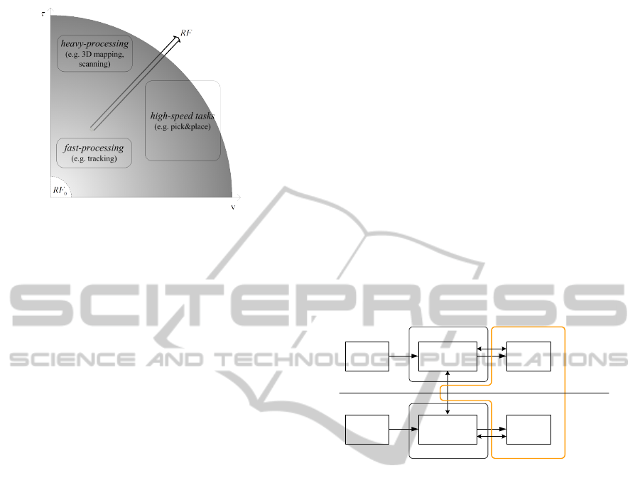
Figure 8: Risk factor map: types of robot applications and
sensing routines in a time vs. speed domain. Gray gradient
represents the superlinear increase of risk factor RF.
While spatial and control inaccuracies may be
considered negligible in most of practical cases, with
ε
calib
+ ε
dyn
≤ 5mm, the latency-dominated inaccu-
racy ε
lat
plays a significant role in building the over-
all blind time-of-flight τ along which the robot moves
without any chance of detection (Fig. 5). The la-
tency component, in fact, assumes the dominant role
in evaluating data from sensors. Considering in fact
a group S of slower devices w.r.t. the group F of
faster devices - e.g. robots - with sampling frequency
[1 − 5)ms 3 T
F
samp
< T
S
samp
∈ [5 − 20]ms, and timing
reasonably being
T
o f f set
≤ T
F
proc
T
S
tx
' T
F
tx
∈ [1 − 5]ms
T
S
proc
= T
S
samp
+ T
S
comput
T
F
proc
,
the sensor processing happens to be the prominent
contributor to the overall time misalignment in data
checking, i.e.
τ ' T
S
proc
ε ' ε
lat
.
As a result, demanding applications, e.g. fast robot
motion - which is currently not allowed in stan-
dards (ISO, 2011b) - and time-expensive environmen-
tal monitoring, happen to require larger tolerances
or larger uncertainty regions (e.g. larger risk factor
Fig. 8) where each check node enters a safe state.
From a SafeNet procedural stand point, the mon-
itoring principle would benefit from a reduction of
such RF or, correspondingly, an improvement in qual-
ity of the sensor channels. The monitoring of chan-
nels, and their quality at large, tend to limit the num-
ber of failures (i.e. d
SE3
> ε) per time unit, signifi-
cantly contributing to the improvement of the system
reliability, which in turn is one of the steering param-
eters in ISO 13489-1:2006 PL assessment.
2.2 Architectural Designation
and Performance Level
The set of architectural actions (Fig. 4), aimed at dif-
ferentiating and doubling the data flow evaluation,
provide the necessary structure of a PL d class of
functional safety. Architecturally this is equivalent to
distributing a SRP/CS over 3 components, being able
to cross-monitor the double data channels. In a ISO
13489-1:2006 Cat.3 architecture with dual channel I-
L-O (input-logic-output) modules (Fig. 9), all moni-
toring functions are, in fact, performed by the safety
functions in the safe node.
From an implementation point of view, this can be
achieved by embodying the check nodes and the safe
node in 3 separate PLCs (Fig. 10) networked through
any suitable protocol (chiefly Ethernet-based) to the
system and mutually through a safe protocol. On
input 1
input 2
logic 1
logic 2
output 1
output 2
CPU 1 safeCPU
CPU 2
channel 1
channel 2
cm
m
m
Figure 9: ISO 13489-1:2006 model for Cat. 3 designated
architecture with deployed SRP/CS components (CPU1,
CPU2 and safeCPU) outlining their logical domain. m
are monitored safe state tasks execution. cm is th ecross-
monitoring of both channels.
top of dual channel architectures (mandatory for PL d
and PL e rating), the actual Performance Level is de-
termined by the degree of reliability, in the form of
mean time to dangerous failures (MT T F
d
), together
with the monitoring capability, in the form of Diag-
nostic Coverage (DC) of a system. The MT T F
d
at
system level is not discussed in detail in this work,
while some considerations are due to highlight that
the DC level of a Cat.3 architecture cannot be null,
i.e. DC < 60%. A minimum requirement DC can be
achieved, for instance for inputs in SRP/CS, through
“monitoring some characteristics of the sensor (re-
sponse time, [...])” (ISO, 2006), with the possibil-
ity of improving the DC through cyclic and/or paral-
lel methods for monitoring the sensor lines (DC up
to 99%). DC rate is normally evaluated for all I-L-
O modules. As an implementation example, a low
range 60% ≤ DC < 90% can be supported by watch-
dog components (Fig. 10) in each channel in charge
of monitoring the availability and timing of (i) the
ICINCO2013-10thInternationalConferenceonInformaticsinControl,AutomationandRobotics
280
HALT
Robot CTRL
check
sources - 2
check
sources - ...
Sensors Processing
check
consistency
SafeCPU
Check node 1
data 1
data 2
check
sources - 1
<safe filedbus>
check
watchdog
check
sources - 2
check
sources - ...
Check node 2
check
sources - 1
check
watchdog
robot
sensors
do
algorithms
data ...
data 1
data 2
data ...
SRP/CS
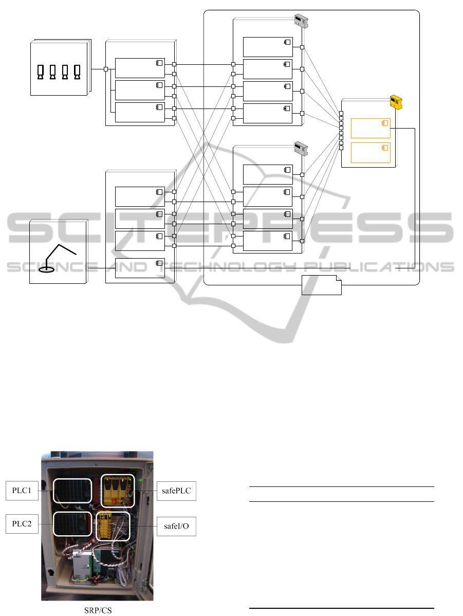
Figure 10: UML deployment diagram of a system made of a robot and a sensor set connected to the SRP/CS made of 2
standard PLCs (check node 1 and 2) and one safePLC (safe CPU). “double to double” connections from/to the SRP/CS
are visible for all data feeds in each data source (data1, data 2, data ...). Watchdogs are present for DC purpose and check
consistency component in SafeCPU node is in charge of handling the safe state. do algorithms component in SafeCPU node
represents the data usage in a functionally safe mode, i.e. through safety functions.
data transfer protocol (e.g. port access) and (ii) the
data sampling/processing routines. In particular, the
L modules in both channels are directly connected to
the safePLC (Fig. 11) through safe protocols, ensur-
ing a supervised output for each channel (m in Fig. 9).
The same apply at inter-logic level (cm in Fig. 9).
Figure 11: Deployed SRP/CS featuring actual hardware
components (PLC1, PLC2 and safePLC).
Finally, ISO 13489-1:2006 requirements for func-
tional safety include also the use of (application-
dependent) well-tried procedures, components and
methods in system development in form of a review
of measures for avoiding the common causes of fail-
ures (CCF) that have to gain a minimum score of 65
according to quantification in Tab. 1.
Table 1: Measures against CCF (common causes of fail-
ures) scores.
measure max score
Separation 15
between the safety circuits
Diversity 20
in design and technologies
Draft / Application / Experience 20
in applying well-tried procedures
Assessment / Analysis 5
Competence / Training 5
of developers
Environmental influences 35
EMC and others
SafeNetofUnsafeDevices-ExtendingtheRobotSafetyinCollaborativeWorkspaces
281
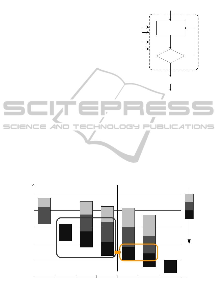
3 CONCLUSIONS
A methodology has been outlined discussing proce-
dural and architectural actions aiming at qualifying a
robotic system with a functional safety rate equal (at
least) to PL d , as requested by ISO 10218-2:2011,
in the case of entire/partial presence of unsafe nodes
(Fig. 12).
The core concept introduced in such a methodol-
ogy (SafeNet of unsafe devices) considers the system
as a device at large, which has to display functional
safety in its parts and nodes. Required level of func-
tional safety has been reviewed to be formulated on
the basis of system-level reliability and monitoring
(MT T F
d
and DC), to require well-tried and consistent
practices (CCF counter-measures), and, most impor-
tantly, to stand on a class of dual channel monitored
architectures where the SRP/CS is able to consistently
check the availability and validity of data feed and
component behaviors. Such structural feature is ob-
tained through the main characteristic of the SafeNet
that involves the creation of procedural and architec-
tural redundancies over the network, variously inter-
connecting robots and sensors. In this way, general
systems of designated architectures Cat.B/1/2 can be
upgraded to Cat. 3 and can provide necessary condi-
tions for PL d rate achievement (Fig. 13). The safety
rate upgrade is mainly in charge of a SRP/CS dis-
tributed on 3 components that provide the structure
for the designated cathegory as well as the reliability
and diagnostic coverage.
PLd?
ISO 10218-2:2011
PL
r
= d
ISO 12100:2010
SafeNet
architecture
SRP/CS design
+ MTTF
d
+ DC
avg
ISO 13489-1:2006
Figure 12: Design and evaluation process for robot sys-
tem safety: application and scenario requirements from ISO
10218-2:2011 are elaborated according to functional safety
procedures (ISO 13489-1:2006) until validation, before pro-
ceeding to general risk assessment in ISO 12100:2010.
ACKNOWLEDGEMENTS
This work has been partially suported by CNR Flag-
ship Program “Factory of the Future”, FdF-SP1-T3.1,
Project FACTOry Technologies for HUMans Safety.
a
b
c
d
e
Cat.
DC
avg
B
none
1
none
2
low
2
medium
3
low
3
medium
4
high
dual channel
MTTF
d
PL
Figure 13: Effect of SafeNet methodology on the PL assessment: a generic network of unsafe devices is outlined in gray box,
while applying redundancy architectural measures it is possible to move to PL d class (outlined in dark yellow).
ICINCO2013-10thInternationalConferenceonInformaticsinControl,AutomationandRobotics
282

REFERENCES
ABB Robotics (2008). EPS and SafeMove White Paper
WHPEPS-20.
Alami, R., Albu-Sch
¨
affer, A., Bicchi, A., Bischoff, R.,
Chatila, R., De Luca, A., De Santis, A., Giralt, G.,
Guiochet, J., Hirzinger, G., Ingrand, F., Lippiello, V.,
Mattone, R., Powell, D., Sen, S., Siciliano, B., Toni-
etti, G., and Villani, L. (2006). Safe and Dependable
Physical Human-Robot Interaction in Anthropic Do-
mains: State of the Art and Challenges. In Bicchi, A.
and De Luca, A., editors, Procceedings IROS Work-
shop on pHRI - Physical Human-Robot Interaction in
Anthropic Domains.
Albu-Sch
¨
affer, A., Haddadin, S., Ott, C., Stemmer, A.,
Wimb
¨
ock, and Hirzinger, G. (2007a). The dlr
lightweight robot: design and control concepts for
robots in human environments. Industrial Robot: An
International Journal, 34:376–385.
Albu-Sch
¨
affer, A., Ott, C., and Hirzinger, G. (2007b). A
unified passivity-based control framework for posi-
tion, torque and impedance control of flexible joint
robots. The International Journal of Robotics Re-
search, 26(1):23–39.
Bicchi, A., Peshkin, M. A., and Colgate, J. E. (2008). Safety
for physical human-robot interaction. In Springer
Handbook of Robotics, pages 1335–1348. Springer
Berlin / Heidelberg.
De Santis, A., Siciliano, B., De Luca, A., and Bicchi, A.
(2008). An atlas of physical human-robot interaction.
Mechanism and Machine Theory, 43(3):253–270.
Decotignie, J.-D. (2005). Ethernet-based real-time and in-
dustrial communications. Proceedings of the IEEE,
93(6):1102 –1117.
Felser, M. (2005). Real-time ethernet - industry prospective.
Proceedings of the IEEE, 93(6):1118 –1129.
Grebenstein, M., Chalon, M., Friedl, W., Haddadin, S.,
Wimb
¨
ock, T., Hirzinger, G., and Siegwart, R. (2012).
The hand of the dlr hand arm system: Designed for
interaction. The International Journal of Robotics Re-
search, 31(13):1531–1555.
Gupta, R. and Chow, M.-Y. (2010). Networked control sys-
tem: Overview and research trends. Industrial Elec-
tronics, IEEE Transactions on, 57(7):2527 –2535.
Haddadin, S., Albu-Sch
¨
affer, A., De Luca, A., and
Hirzinger, G. (2008). Collision detection and reaction:
A contribution to safe physical human-robot interac-
tion. In Intelligent Robots and Systems, 2008. IROS
2008. IEEE/RSJ International Conference on, pages
3356–3363.
Haddadin, S., Albu-Sch
¨
affer, A., and Hirzinger, G. (2009).
Requirements for safe robots: Measurements, analy-
sis and new insights. The International Journal of
Robotics Research, 28:1507–1527.
Hespanha, J., Naghshtabrizi, P., and Xu, Y. (2007). A sur-
vey of recent results in networked control systems.
Proceedings of the IEEE, 95(1):138 –162.
IEC (2010). IEC 61508:2010: Functional safety of
electrical/electronic/ programmable electronic safety-
related systems. International Electrotechnical Com-
mission, Geneva, Switzerland.
ISO (2006). ISO 13849-1:2006: Safety of machinery –
Safety-related parts of control systems – Part 1: Gen-
eral principles for design. International Organization
for Standardization, Geneva, Switzerland.
ISO (2010). ISO 12100:2010: Safety of machinery – Gen-
eral principles for design – Risk assessment and risk
reduction. International Organization for Standardiza-
tion, Geneva, Switzerland.
ISO (2011a). ISO 10218-1:2011: Robots and robotic de-
vices – Safety requirements for industrial robots – Part
1: Robots. International Organization for Standardiza-
tion, Geneva, Switzerland.
ISO (2011b). ISO 10218-2:2011: Robots and robotic de-
vices – Safety requirements for industrial robots – Part
2: Robot systems and integration. International Orga-
nization for Standardization, Geneva, Switzerland.
ISO (2011c). ISO/TS 15066:2011: Robots and robotic de-
vices Collaborative robots. International Organiza-
tion for Standardization, Geneva, Switzerland.
Kock, S., Vittor, T., Matthias, B., Jerregard, H., Kallman,
M., Lundberg, I., Mellander, R., and Hedelind, M.
(2011). Robot concept for scalable, flexible assembly
automation: A technology study on a harmless dual-
armed robot. In Assembly and Manufacturing (ISAM),
2011 IEEE International Symposium on, pages 1 –5.
KUKA Roboter (2012). KUKA.SafeOperation product cat-
alog.
Moakher, M. (2002). Means and averaging in the group
of rotations. SIAM Journal on Matrix Analysis and
Applications, 24(1):1–16.
Moyne, J. and Tilbury, D. (2007). The emergence of in-
dustrial control networks for manufacturing control,
diagnostics, and safety data. Proceedings of the IEEE,
95(1):29 –47.
Pratt, G. and Williamson, M. (1995). Series Elastic Ac-
tuators. In Intelligent Robots and Systems 95. ’Hu-
man Robot Interaction and Cooperative Robots’, Pro-
ceedings. 1995 IEEE/RSJ International Conference
on, volume 1, pages 399–406.
Strobl, K. and Hirzinger, G. (2006). Optimal hand-eye
calibration. In Intelligent Robots and Systems, 2006
IEEE/RSJ International Conference on, pages 4647–
4653.
Tsai, R. (1987). A versatile camera calibration technique
for high-accuracy 3D machine vision metrology using
off-the-shelf tv cameras and lenses. Robotics and Au-
tomation, IEEE Journal of, 3(4):323–344.
Vogel, C., Poggendorf, M., Walter, C., and Elkmann, N.
(2011). Towards safe physical human-robot collabora-
tion: A projection-based safety system. In Intelligent
Robots and Systems (IROS), 2011 IEEE/RSJ Interna-
tional Conference on, pages 3355 –3360.
Zinn, M., Khatib, O., Roth, B., and Salisbury, J. (2004).
Playing it safe [human-friendly robots]. Robotics Au-
tomation Magazine, IEEE, 11(2):12–21.
SafeNetofUnsafeDevices-ExtendingtheRobotSafetyinCollaborativeWorkspaces
283
