
An Industrial Case Study on using Language Workbench Technology
for Realizing Model-Driven Engineering
Xi Zhu
1
, Congchi Phung
1
, Lars Pareto
2
, Staffan Ehnebom
3
, Mikael Krekola
3
,
Magnus Christerson
4
and Mats Helander
4
1
Chalmers University of Technology, Gothenburg, Sweden
2
University of Gothenburg, Gothenburg, Sweden
3
Ericsson AB, Gothenburg, Sweden
4
Intentional Software Corporation, Bellevue, WA, U.S.A.
Keywords: Language Workbench, Projectional Editor, Model-Driven Engineering, Domain-Specific Languages,
Software Interface Development.
Abstract: Model Driven Engineering (MDE) is a proven approach to improve software development processes by
automation. However, traditional development of MDE tooling requires a high upfront cost. Recent
developments in language workbench technologies promise to significantly reduce these investment costs.
By providing domain experts with targeted projections, the speed and quality of delivering customer value
is improved. This paper provides results from an industrial case study in the telecommunications domain
and compares the value of using a language workbench to traditional MDE technologies. Evaluation of the
approach was based on qualitative research strategy which involved a proof of concept implementation and
effort estimations by tooling experts. Our results, using the Intentional Domain Workbench, indicate that
applying a language workbench promises significant improvements in several aspects of MDE based
software development. Most notably in this paper: (1) improved speed in development of domain specific
tooling and (2) improved speed in software development process re-engineering.
1 INTRODUCTION
Model-Driven Engineering (MDE) is a software
engineering paradigm that addresses the problem of
increasing complexity of software by abstraction and
transformation. With MDE, domain experts use
modeling languages which express domain notations
in order to model abstractions for specific problems.
As MDE received wider recognition in the field of
software engineering, a plethora of modeling tools
were introduced.
First generation modeling tools were
characterized by MDE through domain specific
model driven development tools, and realized by an
external tool vendor using conventional
programming languages, e.g., Simulink (Simulink,
2013), Rational Rose Realtime (Selic, 1998) and
Rhapsody (IBM, 2013). In first generation modeling
tools, meta-models, editors, and transformations
were typically concealed, data formats typically
proprietary, and platform adaptations typically
provided by the vendor.
Second generation modeling tools made meta-
models and transformations first class artifacts.
Modeling tools of this generation followed standards
to an increasing degree, and users of these tools
could define their own model transformations. The
second generation modeling tools were characterized
by the Eclipse Modeling Framework (The Eclipse
Foundation, 2013).
Third generation modeling tools addressed the
high development cost of implementing DSLs and
were characterized by complete IDE solutions in
which modeling languages can be realized "in a day
or two". Examples of this generation are Microsoft
Visual Studio DSL Toolkit (Cook et al., 2007) and
MetaEdit (MetaCase, 2013).
Recently, a new type of tool has emerged which
is an evolution of third generation modeling tools.
Language workbenches with projectional editor
provide editable and synchronized views of models,
specifically tailored for users in specific domains
17
Zhu X., Phung C., Pareto L., Ehnebom S., Krekola M., Christerson M. and Helander M..
An Industrial Case Study on using Language Workbench Technology for Realizing Model-Driven Engineering.
DOI: 10.5220/0004688600170029
In Proceedings of the 2nd International Conference on Model-Driven Engineering and Software Development (MODELSWARD-2014), pages 17-29
ISBN: 978-989-758-007-9
Copyright
c
2014 SCITEPRESS (Science and Technology Publications, Lda.)
(Dmitriev, 2004) (Intentional Software, 2013).
Language workbenches promise to significantly
reduce the development effort of constructing DSL
applications and improving the speed in software
development through tailored projections for domain
experts. To our knowledge, there are no published
studies that, in an industrial context, investigate the
values that language workbench technology provides
to MDE based software development processes such
as tooling cost, end-to-end speed, error prevention
and so on, compared to existing MDE solutions.
This paper presents an industrial case study
which investigates how language workbench
technology can improve MDE based software
development processes, in telecommunication
systems development.
The research problem and related research
questions are the following:
RP: How can language workbenches improve
MDE based software development processes?
• RQ1: What process qualities (e.g. speed, cost)
may language workbenches improve in the context
of interface modeling within large scale embedded
system development?
• RQ2: How do X compare between traditional
MDE solutions and language work-bench
solutions., with X ranging over development cost,
end-to-end speed for change requests and other
factors found in RQ1, in the context of interface
modeling within large scale embedded system
development?
The case study applied a language workbench
(the Intentional Domain Workbench from
Intentional Software) to re-engineer an existing
development process for software interface
definitions. To evaluate the approach, the study
employed a qualitative research strategy to compare
the development effort for implementing a domain-
specific tool for software interface definition using a
language workbench, with that of a development
process based on the Eclipse Modeling Framework.
The paper is structured as follows: Chapter 2 lays
the theoretical foundation of the concepts used in
this paper including software interface development
and language workbench technology in particular
the Intentional Domain Workbench; Chapter 3
presents the research methodology including the
design of the case study at Ericsson AB; Chapter 4,
outlines the results of the studies; finally, chapter 5
and 6 discuss the results, and conclusion drawn from
the study.
2 BACKGROUND THEORY
This chapter covers the relevant theory of the
concepts used in subsequent chapters of this paper.
2.1 Software Interfaces in Telecom
Management Network
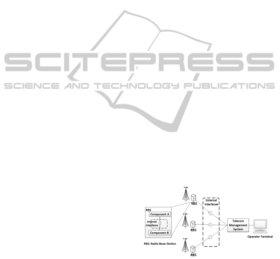
In a telecom management network, network
management systems (NMS) are used for
monitoring and controlling network resources, for
example radio base stations (ObjectStore, 2003). In
current practices, NMS are realized using an object
oriented approach where an object information
model provides abstract representations for the
entities in a network (Breugst et al., 2000). These
abstract representations, managed objects,
encapsulate the underlying network resources and
expose software interfaces which NMS require in
order to handle operations requested by an operator.
Figure 1 illustrates an NMS and several radio base
stations as managed objects in a network. An
operator terminal is used to control and monitor the
network resources through an NMS.
The different interface development
environments address two different types of
software interfaces: external interfaces which
specify the interaction between radio base stations
and the NMS, and internal interfaces which specify
the interaction between the software components
within the radio base station. When new features are
requested or changes are made to the underlying
network resource, the external and/or internal
software interfaces might need to be updated to
reflect these changes.
Figure 1: Software interfaces in a telecom management
network.
2.2 Language Workbenches
Language workbenches denote a category of tools
that according to Fowler (2010) “implement
language oriented programming (LOP)”. Language
MODELSWARD2014-InternationalConferenceonModel-DrivenEngineeringandSoftwareDevelopment
18
oriented programming is based on the concept of
allowing developers to easily define reusable and
interoperable domain-specific languages (DSLs)
(Ward, 1994). Fowler, who coined the term
language workbench, defined the required
characteristics that language workbenches shall
exhibit (Fowler, 2010): “
Users can freely define new languages which are
fully integrated with each other.
The primary source of information is a persistent
abstract representation.
Language designers define a DSL in three main
parts: schema, editor(s), and generator(s).
Language users manipulate a DSL through a
projectional editor.
A language workbench can persist incomplete or
contradictory information in its abstract
representation. “
Voelter, et al. (2013) further extended these
characteristics with the ability to develop complete
programs and the addition of tool support such as
code completion, syntax highlighting and debugger.
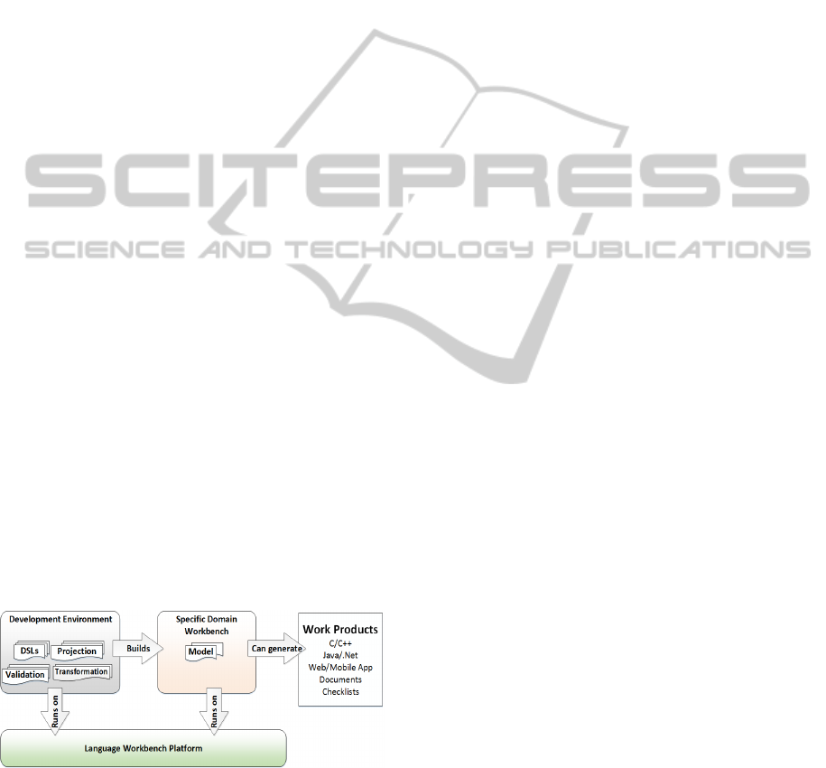
In essence a language workbench is a platform
where interoperable DSLs can be specified and used
to create domain specific encodings which are then
generated to artifacts. An overview of language
workbench technology is shown in Figure 2. As
MDE tools (Brambilla et al., 2012) are based on the
similar idea of using DSLs as modeling language
and transformation to generate artifacts, language
workbenches can be applied in the context of model-
driven software development. The key advantages of
using language workbenches are the creation of
editable views of a user defined representation of the
system. These representations and views are tailored
to specific domains. This domain-specific
representation enables domain users to encode their
solution in notations they find suitable.
Figure 2: Overview of language workbench technology.
In a language workbench the representation can be
presented and edited via multiple projections (that
can be textual and/or graphical.) Projection can be
tailored to only show a view (limited aspects) of a
model thus serving multiple different viewpoints for
different stakeholders and purposes of a system.
Compared to conventional IDE’s, the LWB provides
several benefits: mixing textual and graphical
notations, multiple viewpoint editing while
maintaining consistency across views (Voelter,
2010).
2.2.1 Intentional Domain Workbench
The Intentional Domain Workbench (IDW) is a
commercial language workbench developed by
Intentional Software. The Intentional Domain
workbench is targeted towards business users by
providing projectional editors which allow
manipulation of models described with DSLs in
textual, tabular and graphical notation (Simonyi et
al., 2006). The core elements of a DSLs application,
Knowledge Workbench, developed using IDW
consists of: domain schemas, corresponding to the
abstract syntax (meta-model) of DSLs; domain code,
models described using DSLs; projections, the
editable views provided by projectional editors;
validation rules, which express the constraints of
DSLs; and generators, which given domain code
(model) produces code for specific target platforms.
2.3 Semantic Gap
In language processing theory the semantic gap
refers to (Hein, 2010) “the difference in meaning
between constructs formed within different
representation systems”. In a software engineering
context, semantic gaps occur in the mapping of high
level domain knowledge to machine processable
construct expressed in some proper programming
language. Problems caused by semantic gaps
consist of increased development effort and reduced
software quality (Dhamdhere, 1999) due to
communication issues between domain experts and
software developers (Hein, 2010).
3 RESEARCH METHOD
This chapter presents the research methods used in
this study. An overview of the research methods is
given in Figure 3. The research strategy in this study
is case study research, with software processes for
model based interface specifications being the unit
of analysis. Research methods employed were semi-
structured interviews for data collection on needs;
qualitative analysis for identification of desirable
qualities of interface modeling processes and tools;
proof of concept implementation of an IDW-based
AnIndustrialCaseStudyonusingLanguageWorkbenchTechnologyforRealizingModel-DrivenEngineering
19
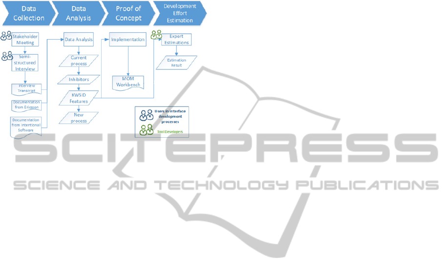
solution; qualitative data collection and qualitative
analysis to estimate and compare the efforts of using
traditional MDE versus using language
workbenches- efforts for implementing the tools as
well as using them.
Figure 3: Overview of the research method.
3.1 Research Site and Informants
The case study was conducted at Ericsson AB, a
worldwide corporation which provides
telecommunication solutions for network operators.
Ericsson AB is divided into business units targeting
different areas within the telecommunication
domain. Our case was a particular MDE based
software development process for interface
definitions used within the business unit Networks.
The process is widely used within the unit, and
utilizes a flora of second generation MDE tools and
technologies. The study focused mainly on two
specific software interface domains (D_int and
D_ext) and its associated tooling. Both use an MDE
approach to automate the transformation of the
interfaces to deployable artifacts. Although users of
the current environments find them useful, there are
several opportunities to increase speed and quality to
strengthen the business units’ competitive advantage
on the market.
The roles of the informants in the case study
include tool developers and users of the EMF-based
environment: a tool developer and a domain expert
from D_ext; two tool developer from D_int. One
domain expert involved with both D_int and D_ext.
The informants are well-versed in the field of
modeling while only developers have practical
experience of using the specific tools of the studied
MDE based development processes. Two research
students were involved with the implementation of
the proof of concept. None of the participants had
previous experience with IDW.
3.2 Data Collection
Data was primarily collected from archival data and
through qualitative enquiry from stakeholder needs.
Semi-structured stakeholder meetings were
conducted to understand the domain and the context
in which MDE is applied in their current
development process. Stakeholder meetings were
held separately for each interface domain with at
least one person. The meetings were conducted
during the period January-May 2013 and the
duration of the meetings varied from 40 minutes up
to 1 hour.
Semi-structured interviews with the informants
of different roles were conducted in order to gain a
better understanding of the specific aspects
mentioned in the stakeholder meetings. The duration
of an interview lasted for approximately 1 hour and
was held during the same time period as the
stakeholder meetings. Interviews were audio
recorded and field notes were taken.
3.3 Data Analysis
The analysis started with transcription of the
recordings of the interviews and stakeholder
meetings. From the transcripts, we identified
keywords and phrases which were categorized as
inhibitors of speed and quality. Based on the result
of the categorization, we identified the reasons for
these inhibitors and the mapping to the different
roles involved in the studied process. We then
identified features and concepts of language
workbenches that would address the possible causes
found in the analysis of the interview. This mapping,
between the causes for the inhibitors and the features
of language workbench technology, was used as
specification for a demonstrator which we iteratively
developed using the Intentional Domain Workbench
(see 3.4 Proof of Concept). Based on the features
provided by the demonstrator, a new process for
software interface development was designed.
3.4 Proof of Concept
A demonstrator for software interface definition of
the studied development process was developed
using the Intentional Domain Workbench. The
mapping between the identified inhibitors and
features of language workbench technology were
used as specification for the demonstrator. The
implementation was done by two research students
with no prior experience of IDW. The demonstrator
was, for each activity and output artifact of the
MODELSWARD2014-InternationalConferenceonModel-DrivenEngineeringandSoftwareDevelopment
20

process, compared with the studied MDE based
software interface process.
3.5 Development Effort Estimation
A qualitative comparison of the development effort
of constructing the demonstrator was made between
the Intentional Domain Workbench (IDW) and the
current tooling environment based on Eclipse
Modeling Framework (EMF). The comparison was
based on expert estimations (Jørgensen, 2007) for
the EMF-based approach and actual development
effort for the IDW approach. The estimates for the
EMF-based approach with additional customized
plugins were given by three tool developers in the
interface domains in three separate sessions with
duration of one hour per session. The tool
developers were asked to use a bottom-up approach
(Jørgensen, 2004) to fulfill the values provided by
the demonstrator. They would proceed with breaking
down the value to concrete tasks and provide an
estimate in person weeks.
The estimates were subject to a number of
constraints. First, estimators were instructed to give
estimates based on tool developers with basic
knowledge in EMF, Eclipse plugin development and
interface definition development. Second, in case an
EMF-plugin was used, they would need to include
the time it would take to familiarize with the plugin.
A guideline listing the constraints and instructions
were used to aid the estimators. Furthermore, in
order to maximize the accuracy of the estimates, a
subset of Jørgensen’s expert estimation guidelines
(Jørgensen, 2004) were applied.
4 RESULT
This chapter presents results from the analysis of the
conducted case- and usability study. First, the
current process of software interface development is
presented together with identified inhibitors. Then,
we describe how a demonstrator based on IDW,
addresses the identified inhibitors. We also present a
comparison of development effort of constructing a
technical equivalent of the demonstrator based on
the current tooling environment in the studied case.
Quotes have been taken from the interviews,
stakeholder meetings and usability testing sessions
in order to strengthen our claims presented in
subsequent sections. Minor changes have been made
to the quotes in order to make them more readable.
4.1 Current Process
4.1.1 Roles
The development of software interfaces involves
mainly the roles listed below.
Feature Developers are responsible for defining
requirements on interface model which fulfill
requested features. Feature developers have
knowledge on solving problems in the telecom
domain. Although many of them are familiar with
modeling, few have knowledge in using MDE tools.
The Review Group consists of two types of
reviewers: domain experts and modeling experts.
Domain experts validates that the proposed changes
satisfy requested features, while modeling experts
make sure that the proposed changes follow the
principles of the design of interface model. The
group reviews delta documents at weekly meetings
and may reject the change requests.
Model developers integrate the changes in delta
documents to the interface model using an EMF-
based modeling tool. Contrary to feature
developers, model developers have a stronger
background in model driven engineering with
knowledge in using MDE tools, while less
knowledgeable about the problem domain.
4.1.2 Artifacts
An Interface Model is a model describing the
software interfaces in radio base stations. The
interface model is defined using an UML-profile
based meta-model in an EMF-based modeling tool.
All entities in the interface model need to follow the
design rules which are constraints from the problem
domain.
Delta document contains a set of proposed
changes to the interface model. The delta document
describes what to be changed in the software
interfaces. Each change refers to requirements of a
specific feature. Thus one delta document represents
one possible solution for realizing the requested
feature. Several delta documents can be proposed as
solutions to realize a certain feature. The delta
documents are stored as spreadsheets or text
documents which are not interpretable by the current
interface development environment.
Deliverables are automatically transformed from
the interface model(s) using an EMF-based
modeling tool. Deliverables are stored as structured
text or binary files, which are input to different
deployment processes.
AnIndustrialCaseStudyonusingLanguageWorkbenchTechnologyforRealizingModel-DrivenEngineering
21
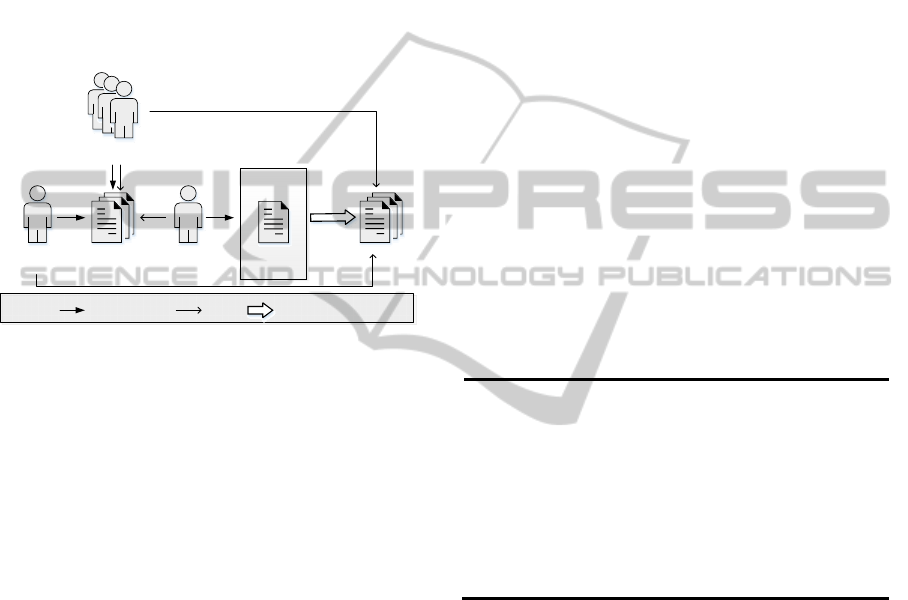
4.1.3 Development Process
Figure 4 presents the current software interface
development process in the case study. As shown in
the figure, an MDE based approach is adopted to
automate the transformation from the interface
model to deliverables ready for deployment.
We illustrate the current development process
with an example in order to explain the roles, the
interactions between the roles and the activities in
the process.
Consider the development of software
components in radio base stations in the context of
Figure 4: Software interface development process for RBS.
network management. Usually, during the
development of software components, changes are
requested for reasons such as changing needs in the
market. Once change requests are accepted for the
next release of the software components, the change
requests are analyzed for feasibility from a technical
point of view. In this specific example, let us
consider a request for a new feature.
First, feature developers who are responsible for
the particular feature analyze the changes that are
required to the existing software component. If there
is a need to make changes to the component, the
component’s software interface must also be
changed in order to support the feature (1). This is
done by the feature developers who define a set of
changes in a delta document. In the specific context
of the study, the software interfaces of the
components are defined as models using a UML
based modeling tool.
Once the feature developers are satisfied with
their solution, the delta document is evaluated by a
review group responsible for the affected software
component interfaces. The review group evaluates a
certain number of delta documents in a review
meeting (2). In a review meeting, the review group
validates the proposed changes according to
predefined design rules and assesses the maturity
level of the delta documents. At the end of the
review meeting, the review group makes the
decision whether to approve the reviewed delta
documents or not. If the delta document did not pass
the review, feedback is sent to the responsible
feature developers who may decide to refine the
delta document to be considered in the next review
meeting.
After a delta document gets approved, the
document will be handed over to model developers.
The model developers are responsible for manually
integrating the changes in the delta documents to the
interface model using specific modeling tools (3).
Once the delta documents are integrated to the
model, automatic transformations (4) can be invoked
to obtain the deliverables which are then used in the
deployment of the new version of the software
component.
4.2 Inhibitors in the Software Interface
Process Development
From analysis of the interview data, inhibitors were
identified in the current development process.
Table 1: Inhibitors in the Software Interface Process
Development.
Inhibitor
IH1 Semantic gap between delta document and
the interface model
IH2 Manual transformations
IH3 Assess impact of change requests to the
interface model
IH4
N
o traceability between interface model
and requirements
IH5
Dependency on modeling tooling expertise
(IH1) Inhibitor: Semantic gap between delta
document and the interface model
Feature developers specify changes to the
interface model through delta documents. The
specification of changes is expressed using concepts
in the interface domain which is represented as
natural language in a delta document. To implement
the changes to the actual model, model developers
need to translate these changes to concepts in the
modeling tool. This semantic gap causes
communication problems between feature
developers and model developers which increase the
development time. A feature developer expressed
the following:
“The persons creating delta MOM are not
working with the actual models. So maybe they can
explain in text what they want to be changed. Then
Deliverable
Model
Developer
Feature
Developer
Review
Group
Modeling
tool
Interface
model
UsesContributesto Automatictransformation
Delta
Legend:
①
②
③④
MODELSWARD2014-InternationalConferenceonModel-DrivenEngineeringandSoftwareDevelopment
22

there is another person who is supposed to interpret
the change. It can happen that the model developer
goes back to the feature developers and say: What
do you mean by this?”
This is further confirmed by a model developer:
“Not everyone is used to the delta document.
Perhaps we need some kind of intermediate format
to make discussions easier.”
(IH2) Inhibitor: Manual transformations
In the current development process, artifacts,
namely the delta document and the interface
document are stored in different data formats.
Currently, no automatic transformation exists
between the data formats. For example, when
changes defined in a delta document are to be
integrated to an interface model, the integration is
done manually by model developers. Both model
developers and domain experts find the process of
manual integration tedious and error prone. One
review group member said:
“The quality of delta document is a problem. One
of our tasks is to check spelling mistakes. [...]There
are several spreadsheets in a delta document. It is so
easy to make mistakes during implementation to the
interface model”.
(IH3) Inhibitor: Assess impact of change requests
to the interface model
In order to assess the changes, feature developers
and the review group rely on information that is
stored in two separate files: the delta document and
the interface model. Typically, a feature developer
or a review group member needs to create a mental
model and then apply the changes to this mental
model to assess the impact of the changes. One of
the domain experts explains the process as the
follows:
“For example, a proposed change is to add a
new attribute to a class. When the review group
assess this proposed change, they need to check if
the attribute is already visible somewhere else,
whether it is proper to do that. In order to assess
that, people need to remember the interface model in
mind”.
This is an activity that requires experience and
becomes even more difficult if the interface model is
large and complex. The same domain expert said:
“For someone not familiar with the interface
model, it is difficult to navigate in the model”.
Domain experts also expressed difficulties in
assessing which elements of an interface model are
affected by a certain change:
“A good idea would be…for a certain change,
which elements in the interface model are affected.”
(IH4) Inhibitor: No traceability between interface
model and requirements
In the current development process, requirements
of features are not modeled in the interface model.
Instead a change in a delta document contains
references by name stored as a plain text, to
requirements. As a consequence, when changes of a
delta document are integrated into an interface
model, references to requirements are lost.
Traceability of requirements is import in the review
of delta documents, especially in cases where the
review group compares a specific delta document
with alternative delta documents:
“It is interesting to keep requirement and feature
information. For example, when the review group
assess a delta document, they want to know if this
solution had been proposed before and its
alternative solutions to the same problem”.
Currently, a review group member needs to rely
on memory to find changes in alternative and
previous delta documents that are related to certain
requirements.
(IH5) Inhibitor: Dependency on modeling tooling
expertise
In the current development process, the
integration of changes in a delta document is done
by model developers with expertise in a certain
modeling tool. As several delta documents can be
reviewed at the same time, the number of model
developers may become a bottleneck in situations
where the rate of processed delta documents are
higher than the rate with which model developers
can integrate delta document changes. A domain
expert in a review group phrased it as:
“[The number of] Model developers would be a
bottleneck in the process if the workload is high”.
A wider adoption of the current tooling among
domain experts is also not likely due to the cost of
training and deployment of the tooling.
4.3 A Knowledge Workbench for
Software Interface Development
Our solution to address the inhibitors in the current
development process is a Knowledge Workbench,
for definition of software interfaces (KWSID) with
features listed in Table 2. A proof of concept
demonstrator for the KWSID was developed.
(KWF1) DSLs for Software Interface Definition
The KWSID implements DSLs for specifying
software interfaces. These DSLs offer both textual
and graphical representations of the system. Both of
these representations can be edited individually. The
AnIndustrialCaseStudyonusingLanguageWorkbenchTechnologyforRealizingModel-DrivenEngineering
23
KnowledgeWorkbench
Uses
Contributesto
Automatic
transformation
Projects
ProjectionAProjectionBProjectionC
Legend
Interfacemodelanddeltas
ModelDeveloper
ReviewGroup
FeatureDeveloper
Deliverable
KWSID will maintain consistency across views.
Table 2: Features of a KWSID.
Features
KWF
1
DSLs for Software Interface Definition
KWF
2
Local Editing, Global Consistency
KWF
3
Stakeholder-tailored Notation
KWF
4
Multiple Representations
KWF
5
Instant Preview of Changes
KWF
6
Live Validation of Design Rules
(KWF2) Local editing, global consistency
The KWSID uses a domain schema that contains
both models for the definition of interfaces and the
delta documents. In KWSID, domain code for
interface models and deltas can be mixed in the
same instance model. The deltas are synchronized
with the interface models thereby providing the
ability to directly make changes while keeping the
interface model consistent.
(KWF3) Stakeholder-tailored Notation
Each role in the current development process is
provided with editable projections synchronized
with the underlying system model. This means
changes made to the system model in one projection
will be reflected in other projections. Moreover,
editing in the tailored notation is supported by
modern IDE features such as code completion and
syntax highlighting.
(KWF4) Multiple Representations
Feature developers can specify changes directly
to the interface model in a tailored projection. The
projection provides multiple editable representations
of the interface elements. Depending on the
situation, feature developers choose how interface
elements shall be projected, for instance as tabular
format, graphical shapes and/or textual format.
Changes made to these interface models are
automatically recorded in deltas.
(KWF5) Instant Preview of Changes
While feature developers are specifying changes,
these changes are previewed on the interface model.
Change markers are supported to indicate the type of
change, the delta that the change belongs to and the
previous value before the change. For feature
developers, domain experts in the review group and
modeling developers, the preview capability
facilitates the process of assessing impact of changes
to the resulting interface model. Furthermore,
KWSID provides the functionality of comparing
deltas by selecting which delta to preview on an
interface model.
(KWF6) Live Validation of Design Rules
The review group has design rules that the interface
models must conform to. These design rules can be
expressed in the KWSID. These rules are checked
continuously while the user is editing an interface
model.
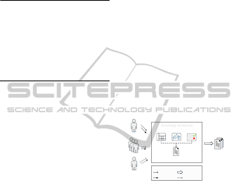
4.4 A New Process for Software
Interface Development
with KWSID
The KWSID can be applied to the current software
interface development process in order to address
the identified inhibitors. Figure 5 illustrates the new
process. Table 3 describes the differences between
the current- and new process.
Figure 5: A new development process enabled by KWSID
for software interface definition.
The inhibitor related to manual transformation (IH2)
is addressed by (KWF1) and (KWF2). As interface
models and changes in deltas are combined in one
instance model, the changes are integrated to the
interface model by automatic transformations
defined in the KWSID. Compared to the current
process, the activity of manual transformation
performed by model developers is replaced by
automatic transformations. Similarly, the manual
transformations done by feature developers, when
defining delta documents, are replaced by the ability
to directly edit the instance model.
For every role in the development process,
KWSID provides tailored projections which allow
the user role to switch between multiple
representations of the interface model elements
(KWF4). In these projections, notations are
MODELSWARD2014-InternationalConferenceonModel-DrivenEngineeringandSoftwareDevelopment
24

specifically customized to suit each user role
(KWF3). In this way, user roles can edit and view
the interface model in multiple ways depending on
their needs while consistency is maintained
throughout all projections. As a result, semantic gaps
between different user roles are reduced and
communication is improved which decreases the risk
of misunderstand and errors (IH1).
While editing, KWSID provides error prevention
features which reduces user editing errors that were
common in the previous process (IH2). For example,
when a feature developer is creating a delta
document, KWSID provides live validation (KWF5)
in order to restrict the feature developer from
violating specified design rules.
For the review group, reviewing changes in
deltas is done through a projection providing instant
preview to assess the impact of changes (KWF5).
For the review group and feature developers, rather
than creating a mental model and imagine the
applied change (IH3), they are given graphical and
textual visualizations of the changes previewed on
the interface model. In addition, the review group is
provided with the ability to comment changes, trace
requirements to elements in interface model and set
the maturity level of delta documents. This type of
information is preserved for later use in the
discussions of the review group (IH4).
The KWSID reduces the workload of model
developers (IH5) due to effects of (KWF3, KWF5,
and KWF6). The model developer role has changed
from manually integrating delta documents to
maintaining the KWSID. KWSID summarizes the
changes in a delta document (KWF2) in a tailored
projection (KWF3). In this projection, deltas are
selected to be integrated to the interface model.
From the interface model transformations are
invoked to generate deliverables. In effect, the
features related to the model developer eliminates
the need for a using a specialized modeling tool for
integration of delta to the interface model (IH5).
4.5 Development Effort Comparison
between Intentional Domain
Workbench and Current Modeling
Tools
Estimations by tooling experts were performed in
order to compare the development effort between
IDW and the studied EMF tooling environment. The
experts were asked to estimate the effort of
developing a domain-specific tool providing similar
value as the KWSID. The result of the estimations is
listed in Table 4. The estimates given for the EMF-
based approaches were based on the realization of
the features of the KWSID. Three values provided
by the KWSID were identified: ability to specify
changes to interface models given by the meta-
model of the interface- and delta definitions;
automation of the integration of delta model to
interface model; tailored projections with features
such as previewing changes for feature developers,
review group and model developers.
Table 3: Comparison between the current development process and the new development process enabled by KWSID.
Role Current Software Interface Development
Process
New Software Interface Development Process
with KWSID
Feature
Developer
Specifies changes in structured text with no
reference to actual interface model
Assesses impact of changes on interface
model using a mental model.
Specifies changes in a preview mode which
shows how the changes will affect the interface
model, and with automatic validation.
Assesses changes through projections showing
previews of how the changes will affect the
interface model.
Review Group
Manually validate design rules.
Assess impact of changes with mental
model.
Has no traceability support from
requirements to the interface model.
Assess changes through projections previewing
how the changes will affect the interface model.
Has traceability of requirements.
Adds information which review group is
preserved in the interface model.
Automatic validation of design rules.
Model
Developer
Manually integrates changes using
modeling tool.
Generates deliverables from models by
automatic transformation
Merges changes to interface models by invoking
automatic transformations.
Views summaries of changes in delta document.
Generates deliverable from interface models by
invoking automatic transformations.
AnIndustrialCaseStudyonusingLanguageWorkbenchTechnologyforRealizingModel-DrivenEngineering
25

Table 4: Estimations of development effort for a DSL application providing same value as KWSID. The development effort
using Intentional Domain Workbench is based on actual data of the implementation of a demonstrator. The unit “x” denotes
the development effort of a person per time unit.
Value EMF
Estimation 1
EMF
Estimation 2
EMF
Estimation 3
IDW
Meta-model for delta
model and interface
model
3x
4x 4.5x 2x
Automation (merge
delta to interface
model)
3x 4x 6x 2x
Projections for feature
developers, review
group and model
developer
8x 28x 28x 6x
Total
14x 36x 38.5x 10x
Three estimates were given, indicating that the use
of IDW decreases the development effort in average
with three times compared to the EMF-based
approaches. For all estimates, the effort of
implementing the domain for the interface- and delta
model is approximately the same with less effort
with IDW. The effort for introducing automation of
integrating delta model to interface model takes in
average two times more effort for the EMF-based
approach. The main difference in effort is from the
implementation of projections where the EMF-based
approaches take in average 3.5 times more effort
than using IDW.
5 DISCUSSION
5.1 Quality of Process Improvements
on the using Language Workbench
Technology
The result of this study shows that the quality of the
current interface development process has improved
by using language workbench technology.
The identified inhibitors on the current process
are inhibiting the speed for which the users are
performing their tasks and the quality of the
resulting output artifacts. The inhibiting effects are
primarily caused by the semantic gap between the
delta document and the interface model i.e. different
constructs expressed in different representation
systems. By only using constructs in one
representation system expressed in different
projections, the need for separate delta documents is
eliminated and thus the semantic gap is closed.
As a result, there are improvements with respect
to speed and artifact quality. Furthermore,
improvements for supporting the user roles of the
interface development process have been observed.
First, the need for manually translating the changes
in delta documents is replaced by automatic
transformations which merge the delta documents
with the interface models in the KWSID.
Eliminating the step with manual translation
increases the end-to-end speed of the development
process. Second, communication and understanding
among user roles are increased due to tailored
projections. A usability test was conducted where
users of different roles of the current process stated
that having different but consistent views of the
interface model would allow them to “make
discussion easier” and “understand the
consequences of the changes” defined in the delta
documents. Third, IDE features in projectional
editors combined with tailored projections ease the
tasks of viewing, defining, and comparing changes
to the interface models. The majority of the users
found it both easier and more useful to work with
the KWSID compared to the current delta document
and tooling environment. Live validation ensures
those delta documents which do not fulfill specified
design rules in the domain will not be passed on to
the next stage of the development process. As a
result, the possibilities of introducing common errors
caused by mistakes and logical errors are captured in
the early phases of the process.
However, uncertainties in the study’s findings
cannot be disregarded without actual deployment of
the KWSID in a real life setting. In such a case,
process qualities may initially decrease due to
unfamiliarity of the KWSID but later to increase due
to the ease of learning and using the workbench. The
ease of use was shown in the usability tests, learning
MODELSWARD2014-InternationalConferenceonModel-DrivenEngineeringandSoftwareDevelopment
26

the DSLs, navigation, interaction and presentation of
information required minimal training.
As shown in previous research of the effects of
DSLs (see chapter 6), suggests that an actual
deployment will provide benefits such as improved
productivity, reduced development costs and
improved maintainability for the user roles in the
process. Overall, the benefits from improved process
qualities, perception, communication and
understanding by using a KWSID, outweigh the
approach and tooling used in the current process.
5.2 Comparison of Development Effort
between IDW and Current MDE
Tooling
A comparison between the IDW-tooling platform
and the current MDE tooling indicates a decrease in
effort when using the IDW. The effort for realizing
the domain, validation rules and introducing
transformation is roughly the same for both
approaches. This is due to the already mature
support for specifying meta-models, validation (e.g.
OCL, VF) model transformations (e.g. ATL, QVT)
in EMF. The difference in effort is instead due to the
design of the meta-models and additional constructs
to support the visualization and specification of
changes to an interface model. This is shown by the
difference of effort it would take for realizing
projections for the roles in the interface development
process. In an EMF-based approach the construction
of concrete syntax is mainly divided into plugins
which support textual syntax (Xtext, TCS) or
graphical syntax (GMF, Graphiti, GMP). In order to
provide the support of both graphical and textual
syntax, considerable effort is required to extend the
plugins to either support both forms of notation or
make the additional plugins interoperable.
Compared with IDW which supports interoperable
DSLs for both textual and graphical syntax, no
additional effort is required. IDW provides a set of
graphical constructs which support common
constructs found in typical word processors such as
tables, headers, lines and boxes. In this aspect, IDW
offers a more flexible and faster approach to
construct domain-specific editors which match the
presentation and notation to domain users than
solutions based on EMF. However, the question
rises concerning the limitations of IDW’s
capabilities of constructing projections. In other
domains which require more advanced graphical
constructs such as 3D-graphics and animations,
would require development of new DSLs which
integrate to target graphics engine. The initial effort
of such an implementation would be equal to an
EMF-based approach but once implemented the
DSLs are reusable and interoperable with other
DSLs, therefore subsequent adaptation to other
domains is minimal.
5.3 Threats to Validity
Interfaces of the kind studied in the paper are very
common in large scale embedded software
development. For example in automotive, aerospace,
industrial automation and other interface intensive
domains. Similar MDE-based development
processes for the interfaces are used with problems
related to semantic gaps. Therefore the comparison
may not be widely generalizable but still replicable.
The implementation of the proof of concept was
done by two research students with basic experience
of using EMF in student projects. The confidence of
the findings could be improved if the
implementation was done by professional developers
with background in software interface development
using EMF.
A threat to the internal validity of the study is the
estimations made by the tool developers. The
number of estimations can be increased in order to
improve the reliability of the findings. Further
improvements would be if the comparison was also
based on an implementation of an EMF-based
approach. However, the tool developers found the
results of the differences in effort, credible. In
addition, measures were taken to increase the
reliability. The tool developers were selected due to
their extensive working experience in the different
interface domains as well as the interface
development processes. Also, guidelines for expert
estimations were applied in order to decrease human
and situational bias.
6 RELATED WORK
To our knowledge there are no published empirical
studies on using language workbench technology in
an industrial context. Several studies exist on the
concept of language-oriented programming
describing possible benefits and disadvantages.
Ward (1994) established the concept of language-
oriented programming and how it was designed to
enable rapid-prototyping and handle challenges in
large-scale software systems such as complexity,
change and conformity. Fowler (2010) coined the
term and characteristics of language workbenches
which implement the concept of language-oriented
AnIndustrialCaseStudyonusingLanguageWorkbenchTechnologyforRealizingModel-DrivenEngineering
27

programming. End-user programmability and ease
of constructing interoperable DSLs are mentioned as
benefits. Voelter et. al. (2010; 2012) further
extended the characteristics and compared the ease
of extending and composing domain-specific
languages for embedded systems with a code-centric
approach (Voelter, 2010). The results in Voelter’s
study indicate significant improvements in
development effort. However, the study is based on
an example with limited scope. Simonyi et.al (2006)
introduced Intentional Software, a language
workbench evolving the ideas of Intentional
Programming (Simonyi, 1995). An evaluation of the
maturity of language workbenches was conducted
by Stoffel (2010) who listed issues of language
workbenches involving integration with existing tool
chains, refactoring DSLs, support for debugging and
unit-testing.
The benefits of DSLs have been shown in several
studies. Kärnä et. al. (2009) evaluated the use of
DSLs in industrial context, which showed
improvement in productivity, usability, quality and
error prevention compared to a non-DSL approach.
Further studies in DSLs using graphical notation by
(Caprio, 2006), Tolvanen et. al. e.g. (2000; 2005) in
industrial contexts and textual notation by (Hermans
et al., 2009) confirm the benefits of the usage of
DSLs to a varying degree.
The high costs of constructing DSLs have been
covered in several studies. Mernik et. al. (2005)
identified problems in current language systems to
support the creation of DSLs and concludes that
process of creating DSLs is still complex and costly.
Similarly, Wu et. al. (2010) stated that although
maintainability of DSLs is improved using DSLs
tools, the development of DSLs is still complex.
7 CONCLUSIONS
In this study, we investigated the influences on
software process quality (end-to-end speed,
development effort, error prevention) for which the
latest generation of MDE technology, language
workbenches, has on MDE-based software interface
definition processes in the context of large-scale
embedded systems. This study was conducted as a
single-case case study at Ericsson AB where we
identified inhibitors of speed and quality in a certain
interface definition process. We also implemented a
proof of concept using the Intentional Domain
Workbench to address the identified inhibitors. We
re-engineered the interface definition process to
support the proof of concept, and asked experts to
compare the development effort to 2nd-generation
modeling tool.
Our results show that language workbench
technology has positive impact on several aspects
compared to the current tooling environment:
The speed in development of domain specific
tooling increased due to flexible projections and
agility in changing the DSLs. These benefits of
language workbenches facilitate rapid software
development process re-engineering.
The end-to-end speed for defining interface
definitions improved due to tailored projections
and the introduction of automation which
eliminates manual tasks in the process. Feature
developers get faster turnaround for requested
changes and model developers get fewer
intermediate steps. Product owners get increased
end-to-end speed and information quality in the
development of new product features.
Improved communication, understanding and
perception for the users in the process due to
flexible projections which are tailored for different
needs.
Furthermore, for modeling researchers, this study
is an empirically example on the benefits of a
multiple viewpoint based MDE solution compared
to a classic transformation based solution.
Further studies are necessary to strengthen our
findings. In particular: studies involving multiple
domains and more complex MDE-based processes;
formal experiments to quantitatively measure the
effects on the changed development processes;
comparison of development effort based on
implementations using current tooling in the studied
context.
ACKNOWLEDGEMENTS
The authors want to express appreciation to
development unit Radio in Ericsson for the valuable
resources to complete this study.
REFERENCES
Brambilla, M., Cabot, J. & Wimmer, M., 2012. Model-
Driven Software Engineering in Practice. Morgan &
Claypool Publishers.
Breugst, M. et al., 2000. Object Oriented Software
Technologies in Telecommunications: From theory to
practice. Chichester: John Wiley & Sons Ltd.
Caprio, G., 2006. Domain-Specific Languages & DSL
Workbench. Dr. Dobb's Journal, (31), pp.38-41.
MODELSWARD2014-InternationalConferenceonModel-DrivenEngineeringandSoftwareDevelopment
28

Cook, S., Jones, G., Kent, S. & Wills, A.C., 2007.
Domain-Specific Development with Visual Studio DSL
Tools. 1st ed. Boston: Addison-Wesley Professional.
Dhamdhere, D.M., 1999. Systems Programming and
Operating Systems. Tata McGraw-Hill Education.
Dmitriev, S., 2004. Language oriented programming: The
next programming paradigm. (Online) JetBrains, at:
http://www.jetbrains.com/mps/docs/Language_Oriente
d_Programming.pdf [Accessed 02 November 2013].
Fowler, M., 2010. Domain Specific Languages. Westford:
Addison-Wesley.
Hein, A.M., 2010. Identification and Bridging of Semantic
Gaps in the Context of Multi-Domain Engineering. In
Goldberg, D.E. & Michelfelder, D.P., eds. Abstracts of
the 2010 Forum on Philosophy, Engineering &
Technology. Colorado, 2010.
Hermans, F., Pinzger, M. & Deursen, A.v., 2009. Domain-
Specific Languages in Practice: A User Study on the
Success Factors. In Schürr, A. & Selic, B., eds. 12th
International Conference, MODELS 2009. Denver,
2009. Springer-Verlag.
IBM, 2013. Rational Rhapsody Developer. (Online)
http://www-142.ibm.com/software/products/us/en/-
ratirhap
Intentional Software, 2013. Intentional Software:
Technology. (Online) http://www.intentsoft.com/-
intentional-technology/
Jørgensen, M., 2004. A review of studies on expert
estimation of software development effort. Journal of
Systems and Software, 70(1), pp.37-60.
Jørgensen, M., 2007. Forecasting of software development
work effort: evidence on expert judgement and formal
models. International Journal of Forecasting, 23(3),
pp.449-62.
Kelly, S. & Tolvanen, J.P., 2000. Visual domain-specific
modeling: Benefits and experiences of using
metaCASE tools. In Proceedings of International
Workshop on Model Engineering, at ECOOP 2000.
Sophia Antipolis, Cannes, 2000.
Kärnä, J., Tolvanen, J.P. & Kelly, S., 2009. Evaluating the
use of domain-specific modeling in practice. In
Proceedings of the 9th OOPSLA Workshop on
Domain-Specific Modeling. Orlando, 2009. HSE Print.
Mernik, M., Heering, J. & Sloane, A.M., 2005. When and
How to Develop Domain-specific Languages. Journal
ACM Computing Surveys (CSUR), 37, pp.316-44.
MetaCase, 2013. MetaEdit+ Domain-Specific Modeling
tools. (Online) http://www.metacase.com/products.h-
tml ObjectStore, 2003. Object Data Management for
Network Management Systems. Progress Software
Corporation.
Selic, B., 1998. Using UML for Modeling Complex Real-
Time Systems. In LCTES '98 Proceedings of the ACM
SIGPLAN Workshop on Languages, Compilers, and
Tools for Embedded Systems. London, 1998. Springer-
Verlag.
Simonyi, C., 1995. The Death of Computer Languages,
The Birth of Intentional Programming. Technical
Report. Redmond: Microsoft Corporation Microsoft
Research.
Simonyi, C., Christerson, M. & Clifford, S., 2006.
Intentional Software. In OOPSLA '06 Proceedings of
the 21st annual ACM SIGPLAN conference on Object-
oriented programming systems, languages, and
applications. Portland, 2006. ACM SIGPLAN.
Simulink, 2013. Simulink - Simulation and Model-based
Design. (Online) http://www.mathworks.se/products/-
simulink/
Stoffel, R., 2010. Comparing Language Workbenches.
MSE-seminar: Program Analysis and Transformation.
Switzerland: University of Applied Sciences
Rapperswil (HSR).
The Eclipse Foundation, 2013. Eclipse Modeling
Framework Project. (Online) http://www.eclipse.org-
/modeling/emf/
Tolvanen, J.P. & Kelly, S., 2005. Defining domain-
specific modeling languages to automate product
derivation: Collected experiences. In 9th International
Conference, SPLC 2005,. Rennes, 2005. Springer-
Verlag.
Ward, M., 1994. Language-oriented programming.
Software - Concepts and Tools, pp.147-61.
Voelter, M., 2010. Embedded software development with
projectional language workbenches. In Proceedings of
the 13th international conference on Model driven
engineering languages and systems: Part II. Oslo,
2010. Springer-Verlag.
Voelter, M. et al., 2013. DSL Engineering - Designing,
Implementing and Using Domain-Specific Languages.
CreateSpace Independent Publishing Platform.
Voelter, M. & Pech, V., 2012. Language modularity with
the MPS language workbench. In Software
Engineering (ICSE), 2012 34th International
Conference., 2012. IEEE.
Voelter, M. & Visser, E., 2010. Language extension and
composition with language workbenches. In
Proceedings of the ACM international conference
companion on Object oriented programming systems
languages and applications companion., 2010. ACM.
Wu, Y., Hernandez, F., Ortega, F. & Clarke, P.J., 2010.
Measuring the Effort for Creating and Using Domain-
Specific Models. In Proceedings of the 10th Workshop
on Domain-Specific Modeling Systems Programming
Languages and Applications: Software for Humanity.
Reno, 2010. ACM.
AnIndustrialCaseStudyonusingLanguageWorkbenchTechnologyforRealizingModel-DrivenEngineering
29
