
Signature Required
Making Simulink Data Flow and Interfaces Explicit
Marc Bender, Karen Laurin, Mark Lawford, Jeff Ong, Steven Postma and Vera Pantelic
Department of Computing and Software, McMaster University, Hamilton, ON, Canada
Keywords:
Simulink, Interfaces, Model Transformation, Refactoring, Software Engineering, Software, Data Flow.
Abstract:
Model comprehension and effective use and reuse of complex subsystems are problems currently encountered
in the automotive industry. To address these problems we present a technique for extracting, presenting and
making use of signatures for Simulink subsystems. The signature of a subsystem is defined to be a general-
ization of its interface, including the subsystem’s explicit ports, locally defined and inherited data stores, and
scoped gotos/froms. We argue that the use of signatures has significant benefits for model comprehension and
subsystem testing, and show how the incorporation of signatures into existing Simulink models is practical
and useful by discussing various usage scenarios.
1 INTRODUCTION
Model-based development using visual programming
languages has become a commonly used method for
the development of embedded software. In particular,
Simulink has been widely adopted for the develop-
ment of control software in the automotive industry.
While the use of model-based development has many
advantages, which have been discussed at length in
the literature (Schatz et al., 2002; Rau, 2000; Rau,
2002), many of the visual languages currently used
for embedded software development lack some of the
traditional software engineering features developers
have come to expect and depend on.
It has become an accepted view in software en-
gineering that system development requires modular-
ization and information hiding (Rau, 2001; Meyer,
1992; Parnas, 1972) to allow for division of tasks
among developers, as well as ease of maintainabil-
ity, comprehensibility, verifiability, and reuse of mod-
ules. The focus of this paper is to bring the basic self-
documentation components of traditional program-
ming languages to Simulink. A traditional imperative
programming language such as C uses function pro-
totypes, variable declarations, and other such mecha-
nisms to aid in the understanding and maintainability
of the code. Importantly, the strict variants of the lan-
guages require that these mechanisms all be defined in
specific parts of the code. Traditionally, in C-like lan-
guages the interface to a module has been defined in a
header file. Simulink does not have any conventions
that can be drawn upon as a parallel to the mechanism
of module interface declarations in C header files that
aid developers’ understanding. This is a weakness of
some visual programming languages, and Simulink in
particular, which we will discuss at length in this pa-
per.
We will focus on using the Simulink subsystem
as the closest analogue to a module, but we will add
structure to what is required in a subsystem in order to
provide a more complete understanding of the subsys-
tem to a developer. This leads to the question, what
comprises a complete understanding of the interface
to a subsystem in Simulink? We feel that the inter-
face of a subsystem in Simulink comes down to the
data flow into and out of the given subsystem, as in
visual languages the data flow is an important com-
ponent to understanding the purpose of the system.
In practice, we have found that it can be difficult to
identify data flow in Simulink. The simple approach
of connecting blocks using signal lines works for sim-
ple models, but as models grow in complexity, this be-
comes inadequate and difficult to maintain. Simulink
includes other mechanisms such as from/goto pairs
and data store memory blocks, which allows the pass-
ing of data without direct connection between. Also
complicating large models is the fact they contain sig-
nificant hierarchies of subsystems. Data flow using
only input and output ports becomes inadequate for
multi-level hierarchies, thus Simulink provides cross-
hierarchical data flow using data store memory blocks
and from and goto blocks that can be accessed at dif-
119
Bender M., Laurin K., Lawford M., Ong J., Postma S. and Pantelic V..
Signature Required - Making Simulink Data Flow and Interfaces Explicit.
DOI: 10.5220/0004716001190131
In Proceedings of the 2nd International Conference on Model-Driven Engineering and Software Development (MODELSWARD-2014), pages 119-131
ISBN: 978-989-758-007-9
Copyright
c
2014 SCITEPRESS (Science and Technology Publications, Lda.)

ferent levels, depending on the scope defined. As we
have not found in literature a comprehensive analysis
of data flow in Simulink, we provide a brief summary
of Simulink data flow in Section 2.
Using the Simulink mechanisms that are avail-
able to aid the developers with the flow of data with-
out using directly connected signals presents chal-
lenges to understanding, navigating, documenting and
maintaining production-scale Simulink models. Upon
opening an arbitrary subsystem, it can be very diffi-
cult to determine its expected context and behaviour.
There is no approach that has been widely adopted
for discovering or presenting a subsystem’s context.
In this paper we present an approach which addresses
this problem. We introduce the notation of signatures
for subsystems in Simulink, which is an embedded
presentation of the interface and the context of the
subsystem. Our proposed signature provides the fol-
lowing main features:
• a data flow legend for each subsystem to ease
comprehension
• the signature can be automatically extracted from
existing models, and automatically updated as re-
quired
• detaches the interface from the subsystem, thus
separating its internal behaviour from its external
manifestation.
Our efforts are motivated by the issues we have
found with data flow in visual languages when mod-
eling large complex system, and the lack of attention
that has been paid to these issues in the literature.
There have been studies done that compare the use
of a visual programming language to a textual pro-
gramming language (Cox et al., 2004; Green and Pe-
tre, 1992). The results of (Cox et al., 2004) show how
presenting developers with both control and data flow
information can aid in the comprehension of Boolean
expressions from code fragments. However, the study
performed by (Green and Petre, 1992) discusses the
fact that visual programming languages are not in fact
easier to read than textual programming languages,
due to the fact that it is harder to simply scan a visual
program, the way one would scan a code fragment.
This conclusion supports our argument for the need
for a subsystem signature to aid the developers in data
flow comprehension within Simulink.
Similar work has been proposed in (Rau, 2002).
In that paper Rau proposes a pattern for strong inter-
faces in Simulink in order to improve typing for in-
puts and outputs. In order to achieve this interface,
Rau proposes that developers follow a particular de-
sign pattern for subsystems. The differences between
the potential use of typing in our proposed signatures
for Simulink subsystems and typing in Rau’s strong
interfaces are discussed in Section 4.
The remainder of the paper is structured as fol-
lows. Section 2 presents a careful analysis of
Simulink data flow constructs and their behaviours.
Section 3 offers a formal definition of abstract signa-
tures, along with a discussion of their properties and
variants. Section 4 is devoted to using signatures in
practice, providing a concrete application of signa-
tures (i.e., used in Simulink models) and discussing
their uses and benefits. Finally in Section 5 we present
ongoing and future work and the conclusion is Section
6.
2 DATA FLOW IN SIMULINK
In this section we present our analysis and criticisms
of data flow in Simulink. Simulink is used for Model-
Based Development and is integrated in Matlab. For
the purposes of the analysis performed, Matlab ver-
sion 7.13 (2011b) and Simulink version 7.8 are used,
however, this analysis should also apply to the most
recent versions of Matlab and Simulink (2013b).
In order to model a large complex system, the abil-
ity to decompose a system into subsystems is required
to make the system comprehensible, maintainable and
allow multiple developers to simultaneously work on
different parts of system. Simulink allows a system to
be embedded in another system, effectively creating
a hierarchy of subsystems. Blocks in Simulink rep-
resent these embedded subsystems as well as built-in
basic functions performed by the system. The blocks
are connected by signals, which represent the data.
Outport
1
Goto Tag
Visibility
{A}
Goto
[A]
From
[A]
Data Store
Write
A
Data Store
Read
A
Data Store
Memory
A
Inport
1
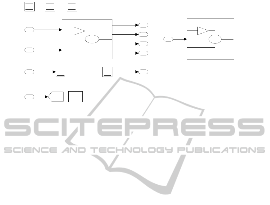
Figure 1: Additional Simulink data flow mechanisms.
In a simple model, following these signals one
can easily understand the system data flow. However,
as models become more complex, it becomes much
harder to follow the connected signals due to the in-
troduction of subsystems, ports, froms and gotos, and
data stores (See Figure 1). We now present some
MODELSWARD2014-InternationalConferenceonModel-DrivenEngineeringandSoftwareDevelopment
120

background information on these mechanisms. It is
important to note that for simplicity we are only using
virtual subsystems (MathWorks, 2013) in our discus-
sion of data flow analysis of Simulink. Non-virtual
subsystems have exceptions as to when these con-
structs can be used and are therefore out of the scope
of this paper. Also, for simplicity of presentation, we
will not be discussing the Simulink Bus.
Subsystems create a hierarchy within the system.
The result is that not all of the relevant information
for a particular subsystem is readily available on that
level in the hierarchy. Necessary information, for ex-
ample signal types or the source of a signal, may come
from further up in the hierarchy. In Simulink, in and
out ports are used to show the incoming and outgo-
ing data for a subsystem. Inports show the informa-
tion that is being fed into the subsystem from outside
and outports show what information the subsystem is
passing back to the subsystem(s) that it is contained
within or the surrounding environment.
From and goto blocks allow for connections to be
made without using a directly connected signal. Infor-
mation passed into a goto block is then propagated on
to all corresponding from blocks. A single goto block
may have multiple from blocks, but a from block may
only receive data from a single goto block. The user
can set the scope of the goto block in the block’s pa-
rameters under tag visibility. The permitted scope of
the goto blocks are:
• Local - The from and goto blocks are used within
the same subsystem. These are identified by
square brackets around the block name.
• Global - The from and goto blocks can be used
anywhere in the mode hierarchy. These are iden-
tified by curly braces around the block name.
• Scoped - The from and goto blocks have limited
visibility. In order to define the scope of a goto
tag, a block called a goto tag visibility block must
be used, which is of the same name as the corre-
sponding from and goto blocks. The from and goto
blocks may be used from within that subsystem
and any subsystem lower in the model hierarchy.
Data stores are used in Simulink as memory.
Through data store read and data store write blocks of
the same name as the data store memory block, a de-
veloper can access this memory. The data store mech-
anism enables the transfer of data without having di-
rectly connected signals in the system. It also allows
for multiple levels of a subsystem to use the same
memory location without needing to pass it through
ports. The scope of the data store is defined by the
location of the data store memory block. The subsys-
tem in which the data store memory block is defined
and any subsystem below it in the hierarchy may ac-
cess the data store through reads and writes. A global
data store is defined as a signal object in the Matlab
workspace, which allows the data store to be accessed
by all models in the workspace. Global data stores
are identified by the keyword “global” appearing in
the block. There also may be multiple read and write
blocks for a single data store memory block. This
introduces issues with the order of access to a data
store. There are three defined order of access errors
associated with data stores:
• Read-Before-Write - A read occurs on the time
step before a write has occurred, which introduces
latency issues, as the model is reading stale data
• Write-After-Read - A write occurs after a read has
already occurred on the time step, which can in-
troduce issues as to whether the read has obtained
the correct value required for execution
• Write-After-Write - A write occurs twice on the
same time step with no read, which can introduce
issues as data is lost
Without explicitly defining the order of executing
of data store read and write blocks, there is the poten-
tial for the order of execution to change in different
releases. (MathWorks, 2008) recommends following
ways to handle the order in which data store read and
writes are executed in a system.
• Use function call subsystems to be able to control
the order the subsystems are executed in
• Set priorities in embedded atomic subsystems or
model blocks
• Utilize diagnostics at compile and run time to de-
tect order of access issues, data stores used in
multiple tasks, and multiple data stores using the
same name
• Use strong typing, which is inherited by the read
and write blocks, to ensure there is no unexpected
use of the data store.
While these Simulink dataflow mechanisms may
be introduced into the model to reduce the number
of blocks and signals that are visible for a given
(sub)system with the goal of aiding comprehensibil-
ity and maintainability, they also introduce issues in
understanding the data flow of a complex model. In
the remainder of this section we will outline the issues
we have encountered while working on large indus-
trial models.
It is possible in Simulink to override a goto tag
visibility or data store memory, by defining a new goto
tag visibility or data store memory of the same name
in a lower level subsystem. Then any access to the
data, whether it be by a from or goto block for the goto
SignatureRequired-MakingSimulinkDataFlowandInterfacesExplicit
121

tag or a read or write block for a data store memory,
will be different depending on the level in the system
hierarchy. This can lead to errors or unexpected be-
havior if the developer was unaware of the multiple
definitions in multiple levels of the hierarchy. Being
able to differentiate within the subsystem where the
definition of the scoped mechanism occurs, either at
the current subsystem level or in a higher subsystem,
could be of value to the developer, especially if they
do not have to spend time searching for this informa-
tion.
For a subsystem, we define the explicit interface as
those items that are clearly dealing with the flow of in-
formation in or out of the given subsystem. Therefore
the explicit interface for a system consists of all in-
ports, outports and data flow mechanisms that are con-
tained within embedded subsystems. The implicit in-
terface are those mechanisms used to reduce the num-
ber of connected signals. The implicit interface con-
tains the from and goto blocks (of all visibility types)
and the data stores defined globally or defined in the
subsystems higher in the hierarchy than the current
subsystem that is being viewed. The imposed inter-
face contains the data stores and goto tag whose vis-
ibility are defined within the current subsystem. The
imposed interface is the definition of the data stores
and gotos within the subsystem, but the actual use of
these mechanisms may occur at a subsystem lower in
the hierarchy.
When viewing a subsystem that is within a large
complex system, the explicit interface is unclear, due
to the fact declarations can be on multiple levels in a
system hierarchy and are not all visible in one place.
The numbered inport and outport blocks are inade-
quate for the developer to know where the data is
coming from or going to on first glance. Another issue
with ports is they can only be used (connected) once
directly before requiring other mechanisms required
to allow for signal branching. When it becomes nec-
essary to branch the signal, we have found from the
automotive industry code we are working with, de-
velopers will commonly feed the inport into a locally
defined goto and use from blocks where the data is
needed (we have incorporated this idea into our con-
crete application of signatures; see Section 4.2).
As with the explicit interface, the implicit and
imposed interfaces are also unclear when viewing
the given subsystem. The information for data that
is defined globally or within a certain scope must
be searched for within the entire system, and the
Simulink ’find’ function is not always adequate to
preform this task. For a developer who is new to a
given system, understanding the data flow can be a
difficult and time consuming task. However, with a
mechanism that can help guide the developer in un-
derstanding the data flow can make the task of un-
derstanding the subsystem quicker and easier. In the
remainder of the paper we will present such a mecha-
nism, the signature for Simulink subsystems.
3 SIGNATURES
We begin by presenting an abstract formal definition
of signatures. A subsystem signature is, essentially,
just a representation of the interface of a Simulink
subsystem. Thus, a signature comprises a set of in-
puts, a set of outputs and a set of declarations. What
makes signatures useful is that they contain not only
the explicit interface (i.e., ports) of a subsystem, but
also its implicit interface (data store reads/writes and
non-local froms/gotos) and its imposed interface (data
store declarations and scoped visibility tags). As
such, signatures have the potential to provide a com-
plete view of the cross-hierarchical data flow in a
Simulink model.
The primary goals of signatures are
• Improve comprehensibility of models by reduc-
ing the need to examine the system hierarchy to
understand data flow,
• Provide ubiquitous information about the subsys-
tems’ implicit interfaces, empowering developers
to use them more effectively,
• Support automatic signature extraction from ex-
isting Simulink models, in order to minimize
overhead in using signatures,
• Open the door to providing stronger control over
interfaces, by using signatures to, e.g., restrict
data flow.
In this section, signatures are defined by set-
theoretic means, and studied from a theoretical point
of view. Our approach is to
1. Provide abstract definitions of subsystems and of
signatures
2. Give inductive definitions of signatures of subsys-
tems
3. Define the notion of consistency for signatures
4. Show how signatures and consistency checking
allow us to restrict and verify interfaces.
Section 4 looks at how to use signatures in practice.
3.1 Preliminaries
In what follows, we will use the following notation.
Sets will be written in the usual way, with {a
1
, . . . , a
n
}
MODELSWARD2014-InternationalConferenceonModel-DrivenEngineeringandSoftwareDevelopment
122

meaning the set containing the n elements a
i
; a ∈ S
means that a is a member of S; S
1
⊆ S
2
means that all
elements of S
1
are contained in S
2
; S
1
∪ S
2
is the set
containing all the elements of S
1
and S
2
; S
1
\S
2
is the
set of elements in S
1
but not in S
2
; and
S
a∈S
f (a) is
the set of all f (a) s.t. a ∈ S. Tuples, that is ordered
sets, are as usual written (a
1
, . . . , a
n
); we will define a
relation ‘v’ on tuples below.
We define a subsystem, for our present purposes,
as an abstraction of the usual notion of a Simulink
subsystem. We see subsystems as merely the set
1
of
ports, froms, gotos, visibility tags, data store reads,
data store writes, data store declarations, and subsys-
tems contained within. Admittedly, abstracting away
subsystems’ internal signal flow gives a somewhat
impoverished view of subsystems, but this is precisely
the idea behind signatures: to simplify data flow anal-
ysis of Simulink models by focusing on their cross-
hierarchical interconnections.
Note also that we only consider normal virtual
subsystems (MathWorks, 2013), in order to simplify
the treatment of data flow. Atomic (nonvirtual) sub-
systems, referenced models, masked subsystems, etc.
all affect the implicit interface in ways that, though
interesting, detract from the presentation of the basic
ideas which we are focused on in this paper. A full
treatment is left to future work.
We also avoid global froms, gotos and data stores
by “faking” them in an obvious way. Global tags are
replaced by scoped tags, with a corresponding visibil-
ity tag placed in the top-level subsystem; global data
stores are replaced by normal data stores, and the cor-
responding declaration is moved to the top-level sub-
system.
Definition 3.1 (Identifiers).
• PO is the set of all port identifiers (essentially just
natural numbers), ranged over by po.
– po
r
represents an input port, and po
w
is an out-
put port.
• DS is the set of all data store names, ranged over
by ds
1
, ds
2
, . . .,
– For any ds, we write ds
d
for its declaration, ds
r
for its read, and ds
w
for its write.
• TG is the set of all scoped tag names, ranged over
by tg
1
, tg
2
, . . ..
– For any tg, tg
d
is its visibility tag, tg
r
its from
and tg
w
its goto.
1
Technically, a subsystem as described here would be a
multiset as, e.g., multiple data store reads might be present
in a single subsystem. We can ignore this in our presen-
tation because it is only the presence (or absence) of the
various elements that we are interested in.
Definition 3.2 (Subsystem Elements). For a subsys-
tem S, define
• Ch (S) = {S
0
| S
0
∈ S}. (the set of all subsystems
contained in S — S’s children in the model hierar-
chy)
• Pa(S) as the S
0
s.t. S ∈ S
0
, if it exists, undefined
otherwise. (the parent of S)
• PO
r
(S) as the set of input ports of S
• PO
w
(S) as the set of output ports of S
• DS
d
(S) = {ds | ds
d
∈ S}
• DS
r
(S) = {ds | ds
r
∈ S}
• DS
w
(S) = {ds | ds
w
∈ S}
• TG
d
(S) = {tg | tg
d
∈ S}
• TG
r
(S) = {tg | tg
r
∈ S}
• TG
w
(S) = {tg | tg
w
∈ S}
With subsystems and their related properties de-
fined, we can now define signatures.
Definition 3.3 (Signatures). Let P ⊆ PO , D ⊆ DS
and T ⊆ TG . A signature Σ is a tuple (I, O, M) (input,
output, and imposed) where
• I = (P
I
, D
I
, T
I
)
• O = (P
O
, D
O
, T
O
)
• M = (D
M
, T
M
)
Intuitively, the inclusion of data stores and scoped
tags in the inputs (outputs) of a subsystem’s signature
indicates that those data stores and tags can be (or are)
read from (written to) in that subsystem. Inclusion of
data stores or tags in the imposed interface is meant
to indicate that those data stores or tags are declared
in the subsystem.
Armed with the above definitions, we can now ex-
amine how to associate signatures with particular sub-
systems.
3.2 Subsystem Signatures
For a given subsystem S, we would like to define a
signature Sig(S) which describes the interface of S
in the most useful way possible. We have found that
there are two complementary and equally important
views of a subsystem’s interface:
1. The view that shows potential inputs and outputs
of a subsystem
2. The view which identifies its actual inputs and
outputs
For a subsystem, we call the first view its weak
signature, written Sig
w
(S), and the second view its
strong signature Sig
s
(S).
SignatureRequired-MakingSimulinkDataFlowandInterfacesExplicit
123

For the weak signature, we wish to discover all
of the data stores and scoped tags which are accessi-
ble to a given subsystem, that is those which are de-
clared higher up in the model hierarchy; for the strong
signature, we aim to enumerate those data stores and
tags which are accessed in a subsystem or its children.
Note that the question of whether or not these are in
fact accessed during the execution of a model is diffi-
cult, and requires deep analysis of control and signal
flow. What we aim to create, for the second view, is a
useful approximation of actual inputs and outputs to
a subsystem simply by checking for the presence or
absence of read blocks and write blocks. This is one
of the strengths of the signature approach: providing
data flow analysis in a setting where semantics are not
available, as is unfortunately the case for Simulink.
In what follows, we will provide inductive defi-
nitions of both weak and strong signatures, and then
in the next subsection a consistency theorem con-
necting the two will be presented. First we define
a convenient projection function on signatures. If
Σ = ((P
I
, D
I
, T
I
), (P
O
, D
O
, T
O
), (D
M
, T
M
)), define
Σ↓
P
I
= P
I
, Σ↓
D
I
= D
I
, etc.
The weak signature is constructed from the top
down, reflecting the fact that it tells us about a sub-
system’s inherited context.
Definition 3.4 (Weak Signature). The weak signature
Sig
w
(S) = ((P
I
S
, D
I
S
, T
I
S
), (P
O
S
, D
O
S
, T
O
S
), (D
M
S
, T
M
S
)) is
defines as follows. Firstly, if S is the top-level sub-
system, then we set
P
I
S
= D
I
S
= T
I
S
= P
O
S
= D
O
S
= T
O
S
= {}
D
M
S
= DS
d
(S)
T
M
S
= TG
d
(S)
Otherwise,
P
I
S
= PO
r
(S)
D
I
S
= Sig
w
(Pa(S))↓
D
I
∪ DS
d
(Pa(S))\DS
d
(S)
T
I
S
= Sig
w
(Pa(S))↓
T
I
∪ TG
d
(Pa(S))\TG
d
(S)
P
O
S
= PO
w
(S)
D
O
S
= Sig
w
(Pa(S))↓
D
O
∪ DS
d
(Pa(S))\DS
d
(S)
T
O
S
= Sig
w
(Pa(S))↓
T
O
∪ TG
d
(Pa(S))\TG
d
(S)
\TG
w
(Pa(S))
D
M
S
= DS
d
(S)
T
M
S
= TG
d
(S)
Remarks 3.5.
1. If a scoped goto is encountered, then the corre-
sponding output is removed from the signature.
This reflects the fact that the same goto cannot ap-
pear more than once (in the same scope).
2. All declarations result in new inputs/outputs on
child subsystems (except if a scoped goto is in the
same subsystem as its declaration).
3. Data stores always appear in both the inputs and
outputs. This is due to the fact that we treat data
stores in the most liberal way that Simulink al-
lows. Disabling various behaviours for data stores
(e.g., write-after-write) could potentially affect
the weak signature; we do not explore this here.
The strong signature is constructed from the bot-
tom up, such that the signature of a subsystem also
reflects its children’s behaviour.
Definition 3.6 (Strong signature). The signature
Sig
s
(S) = ((P
I
S
, D
I
S
, T
I
S
), (P
O
S
, D
O
S
, T
O
S
), (D
M
S
, T
M
S
)) of a
subsystem is defined as follows:
P
I
S
= PO
r
(S)
D
I
S
= (
[
S
0
∈Ch (S)
(Sig
s
(S
0
)↓
D
I
) ∪ DS
r
(S)\DS
d
(S)
T
I
S
= (
[
S
0
∈Ch (S)
(Sig
s
(S
0
)↓
T
I
) ∪ TG
r
(S)\TG
d
(S)\T
O
S
P
O
S
= PO
w
(S)
D
O
S
= (
[
S
0
∈Ch (S)
(Sig
s
(S
0
)↓
D
O
) ∪ DS
w
(S)\DS
d
(S)
T
O
S
= (
[
S
0
∈Ch (S)
(Sig
s
(S
0
)↓
T
O
) ∪ TG
w
(S)\TG
d
(S)
D
M
S
= DS
d
(S)
T
M
S
= TG
d
(S)
Remarks 3.7.
1. Scoped gotos (data store writes) result in out-
puts on the current subsystem and all subsystems
above it until a visibility tag (data store declara-
tion) is reached.
2. If a scoped tag is not included in the outputs (yet),
and a scoped from is found, then the tag is placed
on the inputs. This is done because the corre-
sponding goto is expected to be found higher up
in the model hierarchy.
With the two types of signature defined, we now
explore the connection between them.
3.3 Signature Consistency
To compare two signatures, we define the relation ‘v’
as follows:
Definition 3.8 (Consistency). If I
1
= (P
I
1
, D
I
1
, T
I
1
) and
I
2
= (P
I
2
, D
I
2
, T
I
2
), then I
1
v I
2
⇐⇒ (P
I
1
= P
I
2
∧ D
I
1
⊆
D
I
2
∧ T
I
1
⊆ T
I
2
). Similarly, if O
1
= (P
O
1
, D
O
1
, T
O
1
) and
O
2
= (P
O
2
, D
O
2
, T
O
2
), then O
1
v O
2
⇐⇒ (P
O
1
= P
O
2
∧
MODELSWARD2014-InternationalConferenceonModel-DrivenEngineeringandSoftwareDevelopment
124

D
O
1
⊆ D
O
2
∧ T
O
1
⊆ T
O
2
). Now, for signatures Σ
1
=
(I
1
, O
1
, M
1
) and Σ
2
= (I
2
, O
2
, M
2
), we define
Σ
1
v Σ
2
⇐⇒ I
1
v I
2
∧ O
1
v O
2
∧ M
1
= M
2
.
When Σ
1
v Σ
2
, we say that Σ
1
is consistent relative to
Σ
2
.
Roughly speaking, Σ
1
v Σ
2
means that the in-
put/output behaviour of Σ
1
does not “exceed” that of
Σ
2
. Some additional remarks are in order as to how
the above relation is defined. First of all, notice that if
Σ
1
v Σ
2
, then Σ
1
and Σ
2
must have an identical set of
ports. This is due to the fact that adding and remov-
ing ports from a subsystem is a nontrivial operation,
one that cannot (at present) usefully be expressed us-
ing a signature.
2
On the other hand, the inclusion or
omission of data stores and scoped tags in the im-
plicit interface is less constrained. (Similarly, the set
of declarations in a subsystem is somewhat malleable,
although we do not go into detail about this here; for
our present development weak and strong signatures
are identical.)
Before presenting the consistency theorem be-
tween weak and strong signatures, the concept of va-
lidity of subsystems must be introduced. A subsystem
is valid whenever
• All from tags and goto tags are in the scope of vis-
ibility tags; similarly all data store reads and data
store writes are in the scope of data store declara-
tions.
• There is exactly one goto tag in the scope of each
corresponding visibility tag.
These restrictions are more than reasonable as any
Simulink model that violates them will result in an
error when performing a simulation or code genera-
tion.
Theorem 3.9. Sig
s
(S) v Sig
w
(S) for any valid S.
Proof. By induction on the height of S. The proof is
straightforward.
What is interesting about the above result is that it
does not hold for some subsystems that are not valid.
Specifically, if there are two identical scoped gotos
in two subsystems where one is above the other in
the model hierarchy, then the theorem does not hold.
However, the proof does go through if the two gotos
are in separate subsystems with a common ancestor.
This shows that simply computing the signatures for
subsystems can automatically discover errors before
compile time.
2
However, in future work, when signatures are extended
to support types, the relationship between the ports in two
signatures will be more complex.
Let us explore this idea further to show how signa-
tures can be useful as an analysis tool. Say we (manu-
ally) define some signature Σ for a subsystem S. Then
by computing Sig
s
(S) and Sig
w
(S), we can validate
Σ:
• If Σ 6v Sig
w
(S), then Σ is incompatible with the
context of S. This can mean, for example, that Σ
refers to an undeclared data store.
• If Sig
s
(S) 6v Σ, then S does not satisfy Σ; e.g., S
writes to a data store that is not in the outputs of
Σ.
So signatures can be employed as interface speci-
fications for subsystems, which can be automatically
checked for consistency. As such, a signature can be
used to enforce encapsulation by restricting access to
data, for example, by forcing a data store to be read-
only. Since Simulink provides no such facilities, sig-
natures can be of significant benefit from a software
engineering perspective.
Assume you are given a signature specification for
a subsystem. If the given signature is not consistent
with the generated weak signature, specifically there
are extra data flow mechanisms in the weak signature
that are not in the given signature, it shows the po-
tential for the subsystem to access data flow mecha-
nisms that may cause interference with other subsys-
tems in the model hierarchy. If the given signature
is not consistent with the generated strong signature,
specifically if the strong signature contains data flow
mechanisms that were not in the original given signa-
ture, then the subsystem has access to data flow mech-
anisms it should not. In this case, the designed sys-
tem modularity has been broken. Using the generated
strong and weak signatures can aid in the checking of
a given signature and the implementation of the sub-
system for consistency, as mentioned earlier.
The definitions and theorem above are simplified
for this initial presentation, but they can be refined to
make signatures even more expressive and useful. If
we incorporate types into signatures, then checking
signatures for consistency grows to encompass type
checking.
The consistency-checking technique developed
above demonstrates that signatures can be useful in
practice. In fact, there are many practical ways in
which signatures can be used; the next section ex-
plores these in depth.
4 USING SIGNATURES
With the abstract notion of signature fixed, we now
adopt a more pragmatic viewpoint and explore the ap-
SignatureRequired-MakingSimulinkDataFlowandInterfacesExplicit
125
Subsystem1 Subsystem2
5
4
3
2
1
{scopedA}
{scopedA}
BDS
ADS
CDS
ADS
BDS
5
4
3
2
1
Figure 2: Top level system before signature extraction/inclusion.
plications of signatures in practice. We have already
touched on some practical benefits of signatures in the
last section, namely interface specification, automatic
extraction and consistency checking. Beyond these,
there are many more practical uses and benefits of sig-
natures. Below, we explore some of these uses.
• How to incorporate signatures into a software en-
gineering methodology;
• How to use signatures to (re)organize and classify
parts of subsystem interfaces;
• How to use signatures to aid in a real-world
Simulink refactoring/reverse-engineering effort;
• How to apply signatures to a concrete application,
i.e., included into Simulink subsystems, and how
to automate this process;
• How to use signatures to facilitate testing, model-
in-the-loop simulation and instrumentation;
• How to make use of signatures to apply typing to
subsystems.
We will also present evidence that no change in be-
haviour or performance is incurred when including a
signature in a subsystem.
4.1 Using signatures for Software
Engineering Practices
As mentioned in Section 3, Simulink lacks built-in
data flow management functionality, from the point
of view of providing good subsystem interface man-
agement. Therefore, a discipline is needed to enforce
good design practice at the level of interfaces. The
systematic use of signatures provides just such a dis-
cipline.
Prescriptive Signatures. As an example, imagine
a scenario where a model is under development, and
a new subsystem needs to be created. The context
of this subsystem being fixed, we can automatically
determine its weak signature by using the tool men-
tioned later in this section. This signature can then be
refined by, e.g., removing data stores from the outputs
if they are to be read-only from within the subsystem,
or removing tags altogether if they are not relevant to
the subsystem.
Creating a signature before developing a subsys-
tem (a prescriptive signature) allows for fine-grained
control of data flow throughout the model architec-
ture, which was discussed in detail in Section 3.3. It
provides a mechanism by which we can apply infor-
mation hiding and encapsulation within a Simulink
model.
Classifying Inputs. Making the implicit interface
visible empowers data stores and scoped tags. We
can use these features much more effectively when
they are easy to identify. For example, if we have a
subsystem with some inputs which are dynamic, i.e.,
are changing throughout the execution of the subsys-
tem, and some which are static, that is do not (or
rarely) change. If we apply the discipline of using
scoped tags for static inputs and ports for dynamic
inputs, this significantly declutters the explicit inter-
face of the subsystem. Without signatures, it could
be argued that such an increased use of scoped tags
is detrimental to the comprehensibility of the model.
With signatures, scoped tags are no less visible than
ports.
Refactoring and Reverse Engineering. When
working with large under-documented models, it can
MODELSWARD2014-InternationalConferenceonModel-DrivenEngineeringandSoftwareDevelopment
126
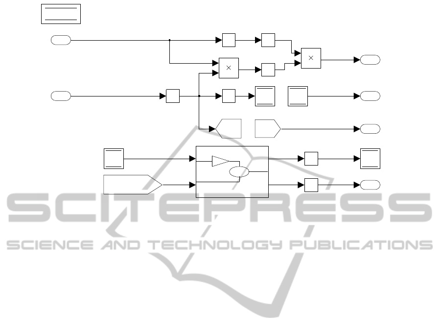
4
3
2
1
1/s
1/s
1/s
1/s
1/s
1/s
1/s
[A]
[scopedA]
[A]
lDS
ADS
lDS
BDS
lDS
2
1
Figure 3: Subsystem1 before signature extraction/inclusion.
be a daunting task to navigate and understand the hier-
archy of subsystems they contain. But if we see sub-
systems as modules, then understanding the interfaces
to subsystems is crucial to proper documentation of
the model. Signature extraction gives us a good start-
ing point for interface documentation, without much
overhead for the developer.
First, computing the weak signature gives an un-
derstanding of the context of a subsystem; by exam-
ining it, we can see if there are any unnecessary tags
or data stores in the interface. Computing the strong
signature for the subsystem can help identify whether
tags and data stores are read from or written to. Fi-
nally, the actual signature for the subsystem would be
somewhere in between, restricting access to context
as fits the situation. Just because a tag is not read in
a subsystem does not mean that it cannot (should not)
be read. A good example of this is a state timer.
From an information-hiding point of view (Parnas,
1972), the signatures at various levels give a poten-
tial method for discovering module secrets, and also
a mechanism to ensure that these secrets are not ex-
posed by the interface.
An interesting usage of signatures in the context
of refactoring is rescoping. In the course of examin-
ing some large-scale industrial Simulink models, we
came across a situation where many data stores were
being defined at or near the top-level of the subsys-
tem hierarchy. This essentially amounts to program-
ming with a large number of global variables, which
is of course undesirable. By computing the weak and
strong signatures for each of the subsystems and com-
paring them, we were able to “push down” declara-
tions automatically to the lowest subsystem possible.
The signatures also provided a clear view of the sizes
of implicit interfaces of all of the subsystems, which,
after the push-down operation, were substantially re-
duced.
4.2 Concrete Application of Signatures
Beyond the abstract definition of signatures given in
Section 3, we can actually express the signature in
Simulink and include it in the subsystem itself. Figure
2 shows the top level of a system, of which we are go-
ing to concentrate on the Subsystem1 on the left. Fig-
ure 3 shows the mentioned highlighted subsystem, for
which we are going to present the extracted strong and
weak signatures. All figures have been created using
the automated signature extraction tool in Simulink
and exported from Matlab.
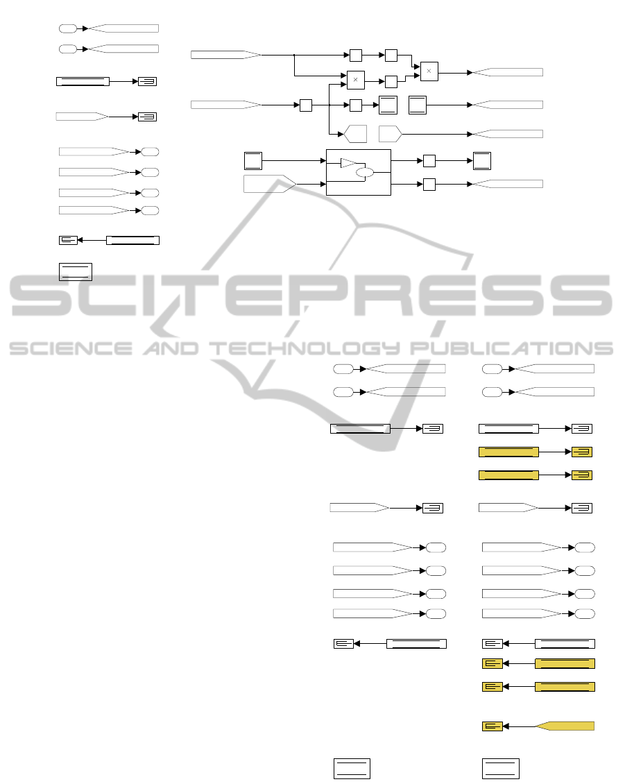
The left hand side of Figure 4 presents the (strong)
signature extracted from the original subsystem. Data
store reads and scoped froms, fed into terminators,
are included for each input and output in the implicit
interface; declarations are grouped together at the bot-
tom. Note that the signature goes beyond simply pre-
senting the interface, but makes the additional step of
feeding all input ports into local gotos, and feeding
output ports from local froms. This step was taken
in our implementation after we observed that our in-
dustry partner’s models used this technique whenever
a port needed to be used multiple times in a model;
in fact, this was one of the initial motivations for the
development of signatures in the first place.
The signature presented in Figure 4 effectively
augments subsystems with a “data-flow legend”. If
applied systematically it serves as a form of self-
SignatureRequired-MakingSimulinkDataFlowandInterfacesExplicit
127
Inputs
Outputs
Data Stores
Scoped Gotos
Declarations
Data Stores
4
3
2
1
1/s
1/s
1/s
1/s
1/s
1/s
1/s
[Out4Goto]
[Out3Goto]
[Out2Goto]
[Out1Goto]
[In1Goto]
[A]
[In2Goto]
{scopedA}
[Out4Goto]
[Out3Goto]
[Out2Goto]
[Out1Goto]
[In2Goto]
[In1Goto]
[scopedA]
[A]
ADS
BDS
lDS
ADS
lDS
BDS
lDS
2
1
Figure 4: Subsystem1 after strong signature extraction/inclusion.
documentation in Simulink; a rough analogy might
be the use of function prototypes and header files in
C. (A signatures effectively provides a data flow view
as defined by (Quante, 2013); in fact, in his defini-
tion of data flow view, he points out that “such views
can be very helpful for tracking data flows through a
system — especially when there are additional hid-
den dependencies.) The signature allows for all im-
plicit and explicit data flow to be found in one place
for a subsystem, instead of opening multiple subsys-
tems to understand the data flow for a single subsys-
tem. We are undertaking a study to demonstrate im-
proved readability and comprehensibility of models
when signatures are included — see Section 5 for de-
tails.
Figure 5 shows both strong and weak signature,
side by side, for the subsystem given by Figure 3. For
this example, it is assumed in Subsystem1 there are
no access to data stores, gotos or froms in the child
subsystem. The highlighted blocks show the differ-
ence between strong and weak signature. The blocks
that are included in the weak signature show what the
subsystem has access to, but is not necessarily using.
The strong signature shows what the subsystem is ac-
tually using.
Automatic extraction of Signatures. The current
prototype of the signature tool is a MATLAB func-
tion, that is executed from the command line. It an-
notates a loaded Simulink model with its signature.
Weak signature is implemented in a recursive top-
down algorithm on the system tree of a model, while
the strong is implemented bottom-up recursive algo-
rithm. The prototype tool has been used on real-world
Inputs
Outputs
Data Stores
Scoped Gotos
Declarations
Data Stores
Inputs
Outputs
Data Stores
Scoped Gotos
Declarations
Data Stores
Scoped Gotos
Strong Signature
Weak Signature
8
7
6
5
4
3
2
1
[In1Goto]
[In1Goto]
[In2Goto]
[In2Goto]
{scopedA}
{scopedA}
{scopedA}
[Out4Goto]
[Out3Goto]
[Out2Goto]
[Out1Goto]
[Out4Goto]
[Out3Goto]
[Out2Goto]
[Out1Goto]
CDS
ADS
BDS
ADS
CDS
ADS
BDS
BDS
lDS
lDS
4
3
2
1
Figure 5: Strong and Weak Signatures for Subsystem1.
examples, but due to the fact that the automotive in-
dustry code we are working with is proprietary infor-
mation that we are not allowed to disclose, we were
MODELSWARD2014-InternationalConferenceonModel-DrivenEngineeringandSoftwareDevelopment
128

not at this time able to publish a real world use case.
Harnessing. Including the signature in a subsystem
provides us with a “plug-in” interface to that subsys-
tem, in that signatures make it easy to attach various
things to subsystems. We can take advantage of this
when developing various kinds of harnesses for sub-
systems, e.g., testing, model-in-the-loop, and instru-
mentation. Importantly, the handling of the implicit
interface when developing a harness is significantly
improved.
There is a considerable lack of proper consider-
ation of implicit data flow in modern testing tools.
More precisely, when generating testing harnesses
for a subsystem, some testing tools neglect to mimic
data passed in/out of the subsystem by data store
reads/writes. We looked into two major commercial
automatic test generation tools
3
to explore cases when
a data store defined outside a subsystem is being read
from or written to in the subsystem. Both tools sup-
port subsystem extraction: a subsystem together with
its necessary execution context is extracted into a new
model, and tests can then be generated for the new
model. The two tools deal with data store reads and
data store writes in different ways. The first tool ex-
tracts the subsystem, and for both data store reads and
data store writes adds only definitions of data stores
(data store memory blocks) to the model, therefore
not taking into account the data flow through inherited
data stores. The other tool also adds the necessary
definitions to the extracted model, but does mimic the
data flow through a data store read: for a given data
store that is being read in the subsystem, an inport
is added that writes into the data store. Further, any
constraints being defined for the data store (minimum
and maximum values) are assigned to the new inport.
When it comes to a data store write, on the other hand,
this tool treats it similarly to a data store read: it adds
an inport that writes into the data store, and then ef-
fectively grounds this input in the generated test har-
ness.
The signature can address the lack of implicit
data flow consideration in test generation, since it ex-
plicitly presents the subsystem’s interface, therefore
clearly identifying implicit data flow in and out of the
subsystem so that it is not overlooked in test harness
generation. Therefore, the signature can be used for
an automatic test harness generation that would ac-
count for all the data passed through the subsystem.
One important note about harnessing using signatures
is that the harness is separated from the rest of the
subsystem, in that it appears entirely on the left-hand
3
Educational licensing terms of these tools do not allow
us to publish the names of the tools.
side. The main benefit of this is that the inclusion
of the harness does not obscure the actual subsystem,
and that in the case where we only have a harnessed
subsystem at our disposal it would be easy to remove
said harness to recover the original subsystem.
Also, adding the strong typing information to the
signature (as presented next in this section) further en-
hances testability: the typing information can be used
to focus test generation only to data of interest.
Typing. Inclusion of the signature in a subsystem
has another major benefit: we can use the patterns
presented in (Rau, 2002) to incorporate strong typing
into subsystems’ interfaces. By using masked sub-
systems or bus objects that ensure that signals are of
a particular type, Rau presents a set of design pat-
terns for Simulink that enforce types on a subsys-
tem’s ports. But there are obvious drawbacks to his
approach. First, the application of his design pat-
terns presents overhead for developers since they es-
sentially need to be programmed by hand. Second,
his typing only applies to the explicit interface of a
subsystem, i.e., its ports. By applying the essential
elements of his approach, attached to the signature as
opposed to included as a pattern, we can apply strong
typing to the implicit interface as well. Typing in this
manner is quite clean as well, as it is completely con-
tained within the signature and thus does not visually
affect the rest of the subsystem.
Behaviour Preservation. An obvious question
which arises when including signatures in a subsys-
tem is whether we have changed the behaviour of that
subsystem. To show that the behaviour has been pre-
served, we provide three arguments: first, by intuitive
analysis of data flow and control flow in the signature;
second, by using coverage testing to profile subsys-
tems before and after signature inclusion; and third,
by comparing the generated code before and after.
Our intuitive analysis follows (Sch
¨
afer et al.,
2009): if name-binding, control flow and data flow
are preserved, then we have a strong argument that be-
haviour has been preserved. By simply analyzing the
patterns in the signature, we can make a simple argu-
ment that we have not changed the behaviour of a sub-
system by including its signature. Ports are fed with
local froms and gotos; as long as we do not choose
conflicting names, these are just shorthand for directly
connected signals so they cannot change behaviour.
Data stores and scoped tags, whether they are inputs
or outputs, are just included in their “read” form (data
store read and scoped from respectively) and fed into
terminators. Here, we can make an easy argument
that data flow has not changed, but it is trickier to ar-
SignatureRequired-MakingSimulinkDataFlowandInterfacesExplicit
129

gue that control flow has not been affected. The ar-
gument hinges on whether or not Simulink optimizes
away a data store read which feeds into a terminator,
or whether it results in the insertion of an extra com-
putation step. In this case, however, control flow can-
not “change” so much as incur a (tiny) performance
penalty. Finally, as far as the declarations go, we are
just moving data store declarations and visibility tags
from within the existing subsystem into the signature.
This is a cosmetic change which certainly should not
affect either data flow or control flow.
To supplement the above intuitive argument, we
have also used a testing tool
4
to perform coverage
testing of a set of subsystems before and after signa-
ture inclusion. The results were identical in all cases.
We also generated code before and after signature ex-
traction; in this case, code was identical (with some
cosmetic changes) for every part of the signature ex-
cept for data stores. When including a data store in
the signature in a case where the data store was not
actually read from or written to in that subsystem, the
generated code contained some extra instructions. Al-
though our own inspection of this supplementary code
leads us to believe that it is nothing more than book-
keeping code, we cannot be sure of its intent or effect
in any context. We need to look at this in more detail
in future work.
5 FUTURE WORK
In order to show the benefits of the proposed signa-
ture for subsystems in Simulink, we plan to perform a
comprehensibility study with software engineers from
our industrial partner. As they already use Simulink
for development, our field of test subjects will already
be familiar with Simulink and data flow mechanisms.
We plan to present them with examples of hierarchi-
cal subsystems with and without signatures and ask
them to identify data flow in the subsystem and per-
form small tasks that involve understanding the data
flow of the overall system. Based on the time it takes
to complete these tasks and feedback we receive from
the software engineers after they have completed the
study, we will be able to draw conclusions on the
benefits of the signature for subsystems in Simulink.
Similar studies have been performed with visual pro-
gramming languages in (Cox et al., 2004; Green and
Petre, 1992). We plan to use these studies as guides
to help create our own.
Besides the study just mentioned, future work will
also include incorporation of signature checking into
4
Educational licensing terms of the tool does not allow
us to publish the name of the tool.
Simulink, further elaboration of type checking using
signatures, including signatures in a comprehensive
software engineering methodology currently being
developed at McSCert, and continuing our work on
harnessing and testing using signatures. In particular,
we would like to extend the work on slicing Simulink
models presented by (Reicherdt and Glesner, 2012)
by elaborating their treatment of data flow; in their pa-
per only explicit signals are treated. Work on creating
a metrics for modularity of the system using the dif-
ference between the weak and strong signatures will
also be explored. Simply this metric would examine
that if there is a large difference in size between the
weak and strong signatures, it means the subsystem
has access to many data flow mechanisms it is not us-
ing, creating the potential for a developer to access
something incorrectly or to interfere with another sub-
system in hierarchy. Work needs to be done on how
to compute a numeric value to represent this metric.
6 CONCLUSIONS
This paper has presented a novel approach to handling
interfaces in Simulink, namely signatures. In our pre-
sentation of signatures, we have striven to present as
complete a picture as possible: from the abstract the-
ory of signatures to the concrete application of signa-
tures in Simulink; motivated by discussion and ex-
amples. The inclusion of signatures in a Simulink
subsystem gives the user one place to get the entire
context of the subsystem, to aid in the user’s compre-
hension of the subsystem’s explicit and implicit data
flow. Also, by examining changes to the strong and
weak signatures during development, we can identify
issues if system modular structure has been broken,
as we have discussed in Section 3. We hope to have
convinced the reader of the usefulness and practical-
ity of signatures. Our industry partner has already ex-
pressed a keen interest in the work and we are cur-
rently collaborating closely with them to develop and
deploy the technique in practice.
REFERENCES
Cox, A., Gauvin, S., and Smedley, T. (2004). Towards com-
prehensible control flow in visual data flow languages.
In International Conference on Distributed Multime-
dia System.
Green, T. and Petre, M. (1992). When visual programs
are harder to read than textual programs. In Human-
Computer Interaction: Tasks and Organisation, Pro-
ceedings 6th European Conference on Cognitive Er-
gonomics.
MODELSWARD2014-InternationalConferenceonModel-DrivenEngineeringandSoftwareDevelopment
130

MathWorks (2008). Best practices for data stores.
http://www.mathworks.com/support/solutions/attach
ment.html?resid=1-6F3I63&solution=1-5NM3AN.
[Online; accessed 20-August-2013].
MathWorks (2013). Subsystem, Automic Subsys-
tem, Nonvirtual Subsystem, CodeReuse Subsystem.
http://www.mathworks.com/help/simulink/slref/ sub-
system.html. [Online; accessed 25-August-2013].
Meyer, B. (1992). Applying “Design by contract”. IEEE
Computer, 25(10):40–51.
Parnas, D. (December 1972). On the criteria to be used in
decomposing systems into modules. Communications
of the ACM, 5(12):1053–1058.
Quante, J. (2013). Views for efficient program understand-
ing of automotive software. Softwaretechnik-Trends,
33(2).
Rau, A. (2000). Potential and challenges for model-
based development: in the automotive industry. Busi-
ness Briefing: Global Automotive Manufacturing and
Technology, pages 124–138.
Rau, A. (2001). Decomposition and interfaces revisited.
Softwaretechnik-Trends, 21(2):19–23.
Rau, A. (2002). On model-based development: A pattern
for strong interfaces in SIMULINK. Softwaretechnik-
Trends.
Reicherdt, R. and Glesner, S. (2012). Slicing MATLAB
simulink models. In Proceedings of the 2012 Inter-
national Conference on Software Engineering, ICSE
2012, pages 551–561, Piscataway, NJ, USA. IEEE
Press.
Sch
¨
afer, M., Verbaere, M., Ekman, T., and de Moor, O.
(2009). Stepping stones over the refactoring rubicon.
In Drossopoulou, S., editor, ECOOP, volume 5653 of
Lecture Notes in Computer Science, pages 369–393.
Springer.
Schatz, B., Prestchner, A., Huber, F., and Philipps, J.
(2002). Model-based development of embedded
systems. Technical report, Technische Universitat
Muchen, Germany.
SignatureRequired-MakingSimulinkDataFlowandInterfacesExplicit
131
