SLMToolBox
A Tool Set for Service Engineering
H. Boyé
1
, H. Bazoun
1,2
and K. Belkhelladi
1
1
Hardis Ouest, 44800 Saint-Herblain, France
2
University of Bordeaux – IMS/LAPS, 33405 Talence Cedex, France
Keywords: Model Driven Engineering, Service Engineering, MDSEA, Life Cycle Management, Eclipse.
Abstract: This paper presents the SLMToolBox (Service Lifecycle Management Tool Box), a software tool which
supports an organization to engineer new services or improve existing ones and to manage its life cycle. The
SLMToolBox is a modeling environment dedicated to the domain of service engineering. It is based on the
Model Driven Service Engineering Architecture (MDSEA) concepts and supports the first phases of service
engineering, in particular: service requirement and service design. The software is developed in the frame of
the IP European Project “MSEE” (Manufacturing Service Ecosystem). This paper presents a guided tour
around SLMToolBox: its architecture, its main components and functionalities.
1 INTRODUCTION
The primary motivation behind the development of
the SLMToolBox is the observation that no
reference tool for designing and managing service
innovation projects currently exists. This fact is
affecting European Manufacturing organization
willing to invest in service innovation as they
currently have to rely on various generic tools,
mostly oriented on « business process management »
and « software engineering » domains.
At top level requirements, we consider that to
create or modify a service within an organization,
the stakeholders need 1) To specify, evaluate,
communicate and design the system supporting the
service and its lifecycle 2) with appropriate
formalisms (domain specific and standard
representations) 3) to rely on productive means and
interoperable data formats and tools.
In order to optimize the development of the IT
components supporting the service, development
teams need to flesh out a solution which is directly
connected to the initial business requirements (e.g.
seamlessly integrates with the business processes of
the organization). Finally, and in order to increase
their productivity, such development activities
should be focused on technical concerns (e.g.
technical design, implementation …).
To address this problematic, an integrated
modeling tool (SLMToolBox) is proposed. This
software is dedicated to the manufacturing services
lifecycle management and it allows an organization
to:
Benefit of a model based architecture (e.g.:
syntactic validation; trans-formation;
execution; …);
Maintain the coherence through the whole
engineering process - from Business
requirements to IT implementation;
Anticipate / simulate the service operation;
Design the governance of the service system.
2 CONCEPTUAL
ARCHITECTURE
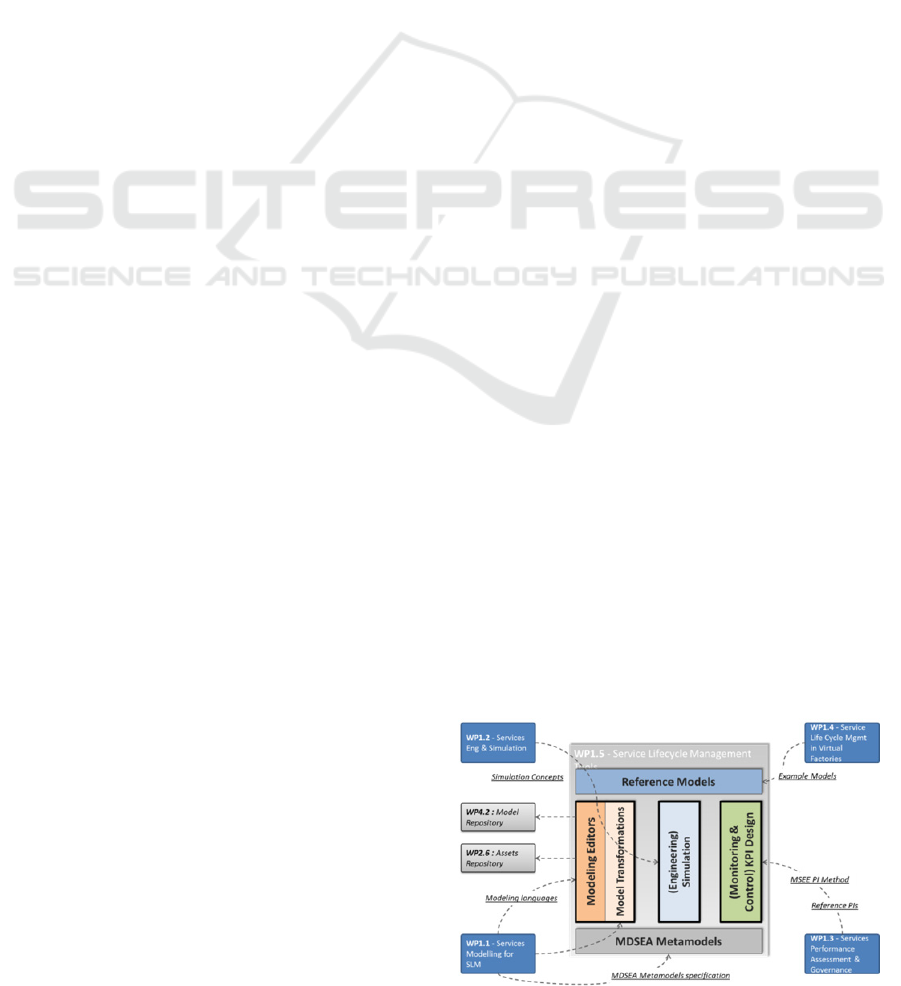
Figure 1: Conceptual architecture.
666
Boyé H., Bazoun H. and Belkhelladi K..
SLMToolBox - A Tool Set for Service Engineering.
DOI: 10.5220/0004876206660672
In Proceedings of the 2nd International Conference on Model-Driven Engineering and Software Development (MDSE-2014), pages 666-672
ISBN: 978-989-758-007-9
Copyright
c
2014 SCITEPRESS (Science and Technology Publications, Lda.)
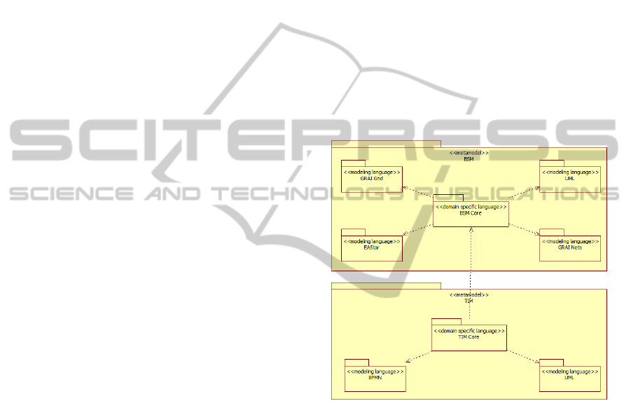
Figure 1 depicts the conceptual architecture of the
toolset. It clearly illustrates the integration of the
outcomes of scientific work packages of the MSEE
(FP7, 2011) project. The overall structure relies on
modeling foundations derived from the MDSEA
(Chen et al, 2012) approach and brings three
complementary pillars: Modeling editors and model
transformations; Simulation; Monitoring & Control.
2.1 MDSEA Foundations
The foundation of the SLMToolBox is based on the
modeling architecture elaborated in the frame of
“service modeling” research work, namely “Model
Driven Service Engineering Architecture”, which is
a specialization of the MDA (OMG, 2003)/MDI
(Bourey et al, 2007) approaches to the domain of
“service engineering”. This model centric approach
provides the appropriate structure for elaborating
service requirements and design, thanks to a set of
specific metamodels dedicated to the domain of
manufacturing services.
Another methodological aspect induced by
MDSEA is the notion of “temporal sequence”
between the elaboration of BSM, TIM and TSM
models. Due to the fact that model transformation
techniques support the transition from one level to
another (e.g.: BSM to TIM, equivalent to
“requirement” to “specifications”), the strategy for
the development of service systems is to adopt a
“waterfall” approach, avoiding the possibility to
elaborate the three modeling levels concurrently, as
the content of one level is strictly dependent on the
upper level.
2.2 Modeling
Several enterprise modeling products now exist in
the market place (e.g. Obeo Designer (Obeo, 2013),
Modelio (Modeliosoft, 2009), etc.). Such tools are
considered to be as enterprise architecture tools. The
approach behind the SLMToolbox is similar in the
sense it is also using a “viewpoints framework”
(ISO, 2011) but differs in its orientation for service
systems modeling domain.
2.2.1 Modeling Architecture
MDSEA defines a set of constructs and relationships
which are specific to the domain of service system
modeling, at three modeling levels: BSM/TIM/TSM
(Chen et al, 2012) in the form of three distinct
metamodels. For each abstraction level, MDSEA
suggests a set of references to standard or former
graphical modeling languages (which are
independent from the domain of “manufacturing
services”) in order to extend and complete the
representation of the system to be modeled, under
different perspectives (e.g.: decision structure;
process; use cases; …).
This type of modeling architecture is based on a
“view model” pattern (or “viewpoints framework”
(ISO, 2011)) as it defines a coherent set of
formalisms to be used, in the construction of a
manufacturing service. The purpose of views and
viewpoints is to enable humans to comprehend
complex systems, to organize the elements of the
problem and the solution around domains of
expertise and to separate concerns. In the
engineering of enterprise systems, viewpoints often
correspond to capabilities and responsibilities within
the engineering organization.
Figure 2: Modeling architecture overview.
Both BSM (Business Service Models) and TIM
(Technology Independent Models) rely on an
equivalent architecture. A “core” metamodel gathers
a set of generic (meta-) data in order to qualify the
service to be modeled (specified / designed) ; this
“core” model refers to external graphical modeling
languages (e.g. : UML (OMG, 2011a), BPMN
(OMG, 2011b)) so that certain aspects of the service
model can be elaborated in more details with the
help of graphical languages. Finally, the role of the
“core” metamodel is to maintain the coherence
between the service meta-data and the several
models which are elaborated to describe the different
aspects (or “views”) of the service.
This structure allows to map “view specific”
modeling languages (e.g.: GraiGrid (Doumeingts et
al, 1998), UML Class Diagram) with “domain
SLMToolBox-AToolSetforServiceEngineering
667

specific” constructs (i.e.: MDSEA BSM) without
introducing modifications or restrictions to the
MDSEA metamodel. From the user point of view, it
allows the possibility to edit core information,
independently from any specific modeling language,
and to retrieve and reuse this data under different
views, accomplished with the help of several
graphical representations (diagrams).
2.2.2 Modeling Editors
The SLMToolBox modeling environment supports
the service system modeling activities by providing
“template” editors for domain specific models (BSM
and TIM “core”) and related modeling languages to
enhance the description of the BSM and TIM
models. In our functional approach, we propose to
provide a set of language specific modeling editors
for each modeling language.
Table 1: SLMToolBox - Modeling Editors overview.
Modeling
Level
Purpose
Modeling
Language
Editor
BSM
Describe service at
high level
BSM
Templates
Specific
Development
BSM
Describe simple
business processes
Extended
Actigram
Star
Specific
Development
BSM
Describe
decisional
structures of the
organization
GRAI
Grid
Specific
Development
BSM
Model the
execution part of a
decision structure
GRAI
Nets
Specific
Development
BSM
Describe
Information
Structures
UML (Use
Case;
Class
Diagrams;
…)
Open Source
Plugin
(PAPYRUS)
TIM
Describe service at
high level
TIM
Templates
Specific
Development
TIM
Describe detailed
business processes
BPMN2.0
Open Source
Plugin
(BPMN2.0
Modeler)
TIM
Specify the IT
artifacts
UML (Use
Case;
Class
Diagrams;
…)
Open Source
Plugin
(PAPYRUS)
2.3 Service Engineering
A user guide will be elaborated, based on the
“service engineering methodology” elaborated in
coherence with MDSEA and strongly connected to
the functionalities of the SLMToolBox – in order to
drive the modeling activities accordingly to the steps
of the service engineering method. Guidance will be
achieved in the form of a dynamic and contextual
help module, directly integrated within the
SLMToolBox modeling environment and tied to the
modeling editors.
2.4 Simulation
At BSM (Business Service Model) level two distinct
views of the service can be elaborated:
Organizational view (formalism : GraiGrid)
Dynamic view (formalism : Extended
Actigram Star)
The organizational view supports the definition
of the “decisional” aspects of the service, thanks to
the GRAI Grid formalism.
On the other hand, the dynamic view is a
representation of the behavior of the static
components of the system, and consists of a
sequence of operations, state changes, activities, and
interactions (i.e.: business processes). A dynamic
model is flexible as it can change with time as it
shows what an object does with many possibilities
that might arise in time.
As a result, we propose to elaborate service
simulation features on the basis of “Business
Process” models formalized with Extended
Actigram Star language (Bazoun et al, 2013). The
simulation will be based on two complementary
criteria:
Time (estimation of the time needed for a
process execution, and of tasks within this
process. We should distinguish here between:
minimum estimated time, maximum estimated
time, and average process estimated time);
Cost (represented by the cost of resources
allocated for the process’s execution).
In addition the service’s quality is assessed
through the assessment of time and cost criteria’s
with their targeted objective values.
2.5 Monitoring and Control
The third pillar (figure 1) supports the definition of
the governance of the service system, which will be
then implemented by the organization to
continuously assess the performance of the service,
MODELSWARD2014-InternationalConferenceonModel-DrivenEngineeringandSoftwareDevelopment
668
according to the three decision levels of the
organization (Strategic; Tactic; Operational), its
functions and its detailed objectives. The
functionalities proposed by the SLMToolBox
consists of an extension of the “GRAI Grid”
diagram editor, allowing to define decision
variables; objectives and performance indicators for
each decision center of the system. Finally, the tool
proposes a reference list of performance indicators,
categorized by domain and aggregation level (i.e.:
enterprise or virtual enterprise) according to the
service governance method defined in the MSEE
project.
3 USAGE SCENARIO –
INTERACTIONS WITH OTHER
MSEE PLATFORMS
3.1 Scenario Overview
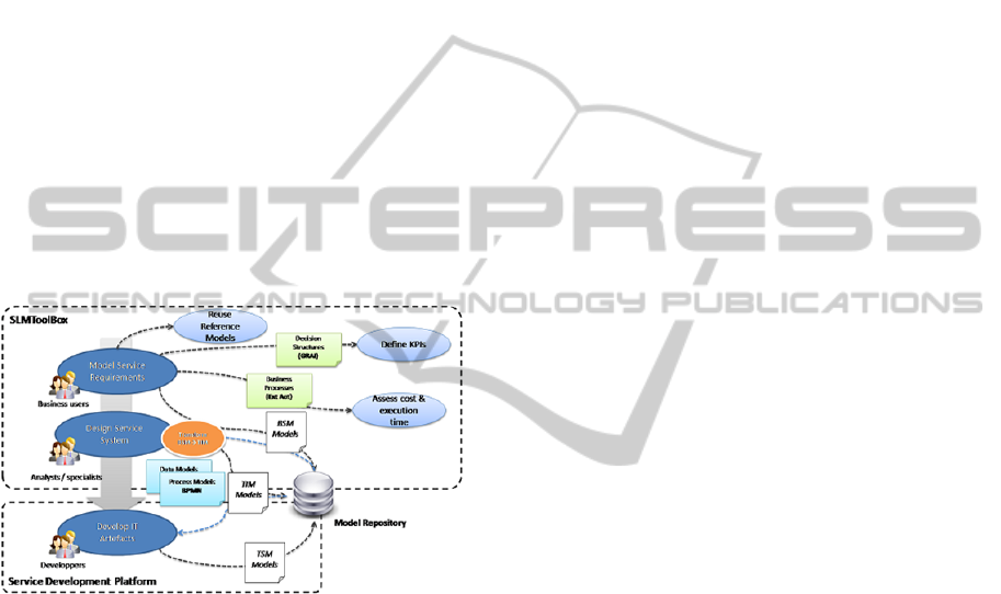
Figure 3: Scenario : Design a new service within a single
enterprise.
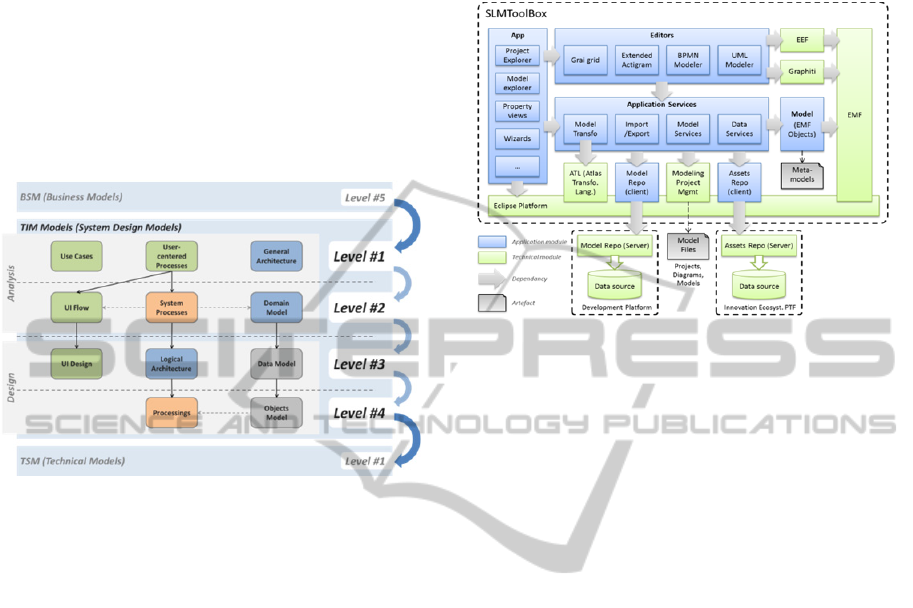
As reflected in the logical architecture overview
(figure 3), the SLMToolBox interacts with two
external systems.
Model Repository Module: the models
elaborated with the SLMToolBox are stored
(published and retrieved) in the model repository
module. Its responsibility is to guarantee the access
to service modeling projects (at BSM; TIM and
TSM levels) between the platforms of the overall
MSEE IT system, and to manage the relevant access
rights and policies. Furthermore, this centralized
repository module will enable several instances of
the SLMToolBox to share service models.
Assets Repository Module: this repository is
responsible for storing and sharing the description of
virtualized assets between several members of a
Manufacturing Virtual Enterprise (VME).
The scenario (figure 3) depicts how the
SLMToolBox can be used to design a new service,
within a single enterprise.
3.2 Scenario Description
3.2.1 Model Service Requirement
(Supported by the SLMToolBox –
BSM Modeling Features)
(a) Reuse reference models : the business user has
the possibility to browse the model repository
and search for a convenient reference model to
start modeling the service requirements in a
BSM modeling project.
(b) A BSM model is initialized and enriched trough
the template editor (for generic service
description) and extended with graphical models;
the BSM models are stored within the model
repository, shared with the rest of the MSEE IT
system. The overall modeling process at BSM
level follow the “BSM Service Modeling”
method, derived from “Service concepts, models
and method: Model Driven Service Engineering
Architecture” (Chen et al, 2012)
(c) The governance system of the service is modeled
through the GraiGrid editor.
(d) The KPIs of the service are defined on the basis
of the GRAI grid model.
(e) Business processes are elaborated with the
Extended Actigram Star language.
(f) Some of these processes can then be simulated in
order to assess their execution time and cost.
3.2.2 Design Service System (Supported by
the SLMToolBox – TIM Modeling
Features)
(g) The first step of the design phase is to retrieve
the BSM models from the model repository and
to initialize a TIM modeling project, thanks to
automatic model transformation techniques.
(h) A TIM model is initialized and enriched trough
the template editor (for generic service
description) and extended with graphical models
; the BSM models are stored within the model
repository, shared with the rest of the MSEE IT
system.
(i) UML models are elaborated via the UML
modeler.
(j) Extended Actigram Star process models from the
BSM modeling project can be automatically
transformed into BPMN process models, either
SLMToolBox-AToolSetforServiceEngineering
669
“collaboration diagram” or “process models”.
The resulting BPMN models are attached to the
current TIM modeling project.
(k) BPMN process models can be modified /
enriched by the user, within the TIM modeling
project.
3.2.3 Development of IT Components /
Artifacts (Supported by the Service
Development Platform)
(l) The development platform retrieves the TIM
models from the model repository.
(m) TSM models are initialized from the TIM
models and enriched with software code in order
to develop executable software components.
4 SERVICE MODELING AT BSM
LEVEL
4.1 High Level Description of the
Service (MDSEA BSM Templates)
A simple template editor allows editing BSM
models in coherence with visual representations of
the service (Extended Actigram Star for “process”
view and GRAI Grid editor for “decisional” view)
4.2 Definition of the “Process” View
Process Modeling is commonly recognized as a
major requirement for business managers and
analysts as there is an increasing emphasis in
organizations to document, understand and improve
their business processes. It offers significant benefits
to companies and organizations such as:
Align operations with business strategy;
Improve communication process;
Increase control and consistency;
Improve operational efficiencies.
Extended Actigram Star (EA*) (Bazoun et al,
2013) relies on previous work developed in the
frame of the GRAI Methodology (Doumeingts et al,
1998), which defines “GRAI Extended Actigram” as
a process modeling language, among other graphical
formalism, for enterprise modeling and “decision
centric” analysis. Figure 4 shows a screen shot of the
Extended Actigram Star Editor with an example
diagram. The goal of Extended Actigram Star is to:
Provide a common and simple modeling
notation that is understandable by business
users, for the description of business process;
Reduce the gap between the ideation and the
design of business process (by its simple and
accessible syntax);
Facilitate the transformation of business
process models toward other structured
modeling languages offering more detailed
constructs.
Figure 4: Extended actigram star diagram example.
4.3 Definition of the “Decisional” View
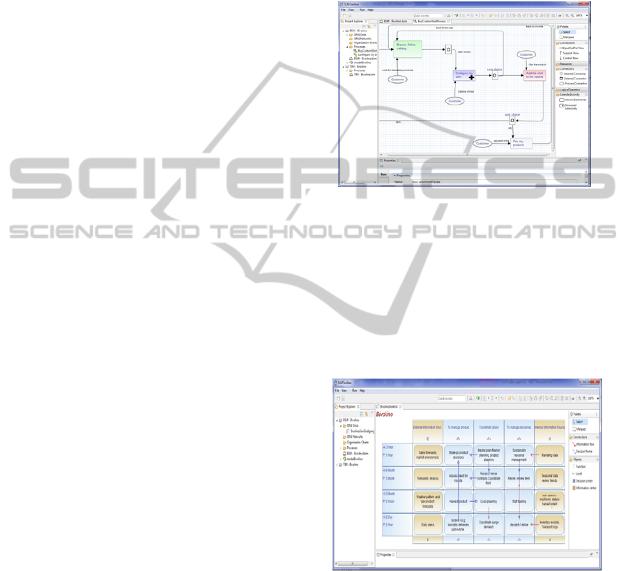
Figure
5
shows a screen shot of the GRAI Grid
Editor with an example of a GRAI grid diagram.
Allowing to visually compose the decisional system
of the organization according to the GRAI
methodology.
Figure 5: GRAI grid diagram example.
5 SERVICE MODELING AT TIM
LEVEL
Figure 6 depicts the overall modeling process and
intermediate TIM levels.
In the SLMToolBox, the BSM and TIM projects
are managed separately so that different categories
MODELSWARD2014-InternationalConferenceonModel-DrivenEngineeringandSoftwareDevelopment
670
of users (e.g. : business analysis ; software
engineers) can collaborate for elaborating a
complete service model at BSM and TIM ; involving
different but complementary skills and knowledge.
A simple template editor allows to edit TIM
models in coherence with visual representations of
the service (UML models for “information” view
and BPMN for “process” view)
In order to maintain the coherence between the
requirements of BSM and the specifications at the
TIM level, model transformation is proposed.
Figure 6: TIM Models decomposition.
6 TECHNICAL ARCHITECTURE
The Eclipse Platform has been chosen as the
technical layer for the implementation of the
SLMToolbox ; as it satisfies the following
requirements of the project : To be open, modular
and extensible ; Rely on best of breed open source
technologies ; Ease the integration with third party
MSEE IT platforms and tools. Considering its
background in research projects, the large
community supporting the development of the core
platform, and its rich ecosystem of plugins, the
Eclipse Platform (Eclipse, 2013) is considered as
one of the most viable open source solutions for
building domain specific modeling environments.
The following figure gives an overview of the
several technical components that compose the
modeling environment of the SLMToolBox.
The Eclipse Modeling Framework – EMF (EMF,
2013) provides a modeling infrastructure for
describing metamodels and editing models with the
help of Ecore format and code generation facilities.
EEF (EEF, 2013) aims at providing new services
dedicated to editing and using more appealing
editing elements for EMF models. As EMF, EEF
relies on a generative approach to provide advanced
editing services Graphiti (Graphiti, 2013) offers
powerful means for building graphical diagrams
editors upon EMF based domain models.
Figure 7: Technical architecture overview.
The SLMToolBox has to support the integration
of standard external models and graphical “model to
model” transformation (example: Extended
Actigram Star models to BPMN models). In this
context, model transformation (Agostinho et al.,
2014) is identified as a transversal feature to be
implemented in the Modeling Environment. To
fulfill this need, ATL Transformation Language
(Jouault et al., 2008 ) is identified as a good option,
as it is developed on the top of the Eclipse Platform
and relies on transformation rules description to
produce target models from a set of source models.
7 CURRENT STATUS
AND FUTURE DIRECTIONS
The SLMToolBox has been successfully used as a
support tool for two of the industrial pilot test cases
of the MSEE project. A final prototype has been
released in October 2013. In its current version, the
prototype can be used to build models of “As-Is”
and “To-Be” situations, in order to support the
“requirement” and “design” phases of the service
lifecycle – at both BSM and TIM levels. Giving an
implementation of the concepts of MDSEA, the
modeling environment allows to model: Service,
Service System to produce the service, resources to
support the delivery of the service, governance of
the service system.
In term of perspectives, on the technical side,
the SLMToolBox is designed to fulfill the
integration requirements of the overall MSEE IT
Architecture; but the possibility to allow a
SLMToolBox-AToolSetforServiceEngineering
671

standalone usage outside of the scope of MSEE is
considered as a core constraint. The capability of the
software to be reused as a separate and self-
consistent tool enables future scenarios in which the
SLMToolBox may be leveraged in cases that have
different technological requirements from those of
MSEE. On the side of use cases, the extension of
modeling features to the management of virtualized
assets will be introduced; this opportunity will be
explored into more details in the following period
with the contribution of MSEE partners, once the
architecture (data models; software support) for
assets virtualization and management will be
finalized. From the research perspective, this use
case would bring the challenge of federating MSEE
ontological and semantic approaches with MDSEA
model centric architecture.
ACKNOWLEDGEMENTS
Authors would like to acknowledge the European
funded Project MSEE (FP7 284860) that supported
partially the work developed and presented in this
paper.
REFERENCES
Agostinho, C., Bazoun, H., Zacharewicz, G., Ducq, Y.,
Boyé, H. and Goncalves, R. (2014) “Information
Models and Transformation Principles applied to
Servitization of Manufacturing and Service Systems
Design” paper accepted to be published in the
proceedings of MODELSWARD international
conference 2014.
Bazoun, H., Zacharewicz, G., Ducq, Y. and Boye, H.
(2013) "Transformation of Extended Actigram Star to
BPMN2.0 in the frame of Model Driven Service
Engineering Architecture" - Proceedings of the
Symposium on theory of Modeling and Simulation.
Bourey, JP., Grangel R., Doumeingts G., and Berre A.
(2007). Deliverable DTG2.3 from the INTEROP
project. “Report on Model Driven Interoperability.”
http://interop-vlab.eu (accessed November 15 2013).
Chen, D., Ducq, Y., Doumeingts, G., Zacharewicz, G. and
Alice, T. (2012) "A Model Driven Approach for the
Modeling of Services in a Virtual Enterprise" - I-ESA
12 proceedings.
Doumeingts, G., Vallespir, B. and Chen, D. (1998) "GRAI
grid, decisional modeling" - Handbook on
Architecture of Information System. International
Handbook on Information Systems.
Eclipse (2013) [Online], available: http://www.eclipse.org/
(accessed 20 November 2013).
EEF (2013) [Online] available: http://wiki.eclipse.org/EEF
(accessed 20 November 2013).
EMF (2013) [Online] available:
http://www.eclipse.org/modeling/emf/ (accessed 20
November 2013).
FP7 – FoF-ICT-2011.7.3. 2011. “Manufacturing SErvice
Ecosystem Project- Annex 1 description of work”.
[Online], available: www.msee-ip.eu (accessed 15
November 2013).
Graphiti (2013) [Online] available:
http://www.eclipse.org/graphiti/ (accessed 20
November 2013).
ISO (2011) ISO/IEC/IEEE 42010:2011, "Systems and
software engineering — Architecture description".
Jouault, F., Allilaire F., Bezivin J., and Kurtev, I. (2008)
“ATL: A model transformation tool”- Science of
Computer Programming.
Modeliosoft (2009). “Modelio” [Online], available:
http://www.modelio.org/ (accessed 04 December
2013)
Obeo (2013). “Obeo Designer” [Online], available:
http://www.obeodesigner.com/ (accessed 04
December 2013)
OMG. (2003) “MDA Guide Version 1.0” document
number:omg/2003-05-01.OMG. (2011a) "Unified
Modeling Language (OMG UML), Infrastructure
Version 2.4.1" [Online], available:
http://www.omg.org/spec/UML/2.4.1/Infrastructure/P
DF/ (accessed 18 October 2013)
OMG. (2011b) "Business Process Model and Notation
(BPMN) Version 2.0" [Online], available:
http://www.omg.org/spec/BPMN/2.0/PDF/ (accessed
20 November 2013).
MODELSWARD2014-InternationalConferenceonModel-DrivenEngineeringandSoftwareDevelopment
672
