
Towards an Automatic Motion Coaching System
Feedback Techniques for Different Types of Motion Errors
Norimichi Ukita
1
, Daniel Kaulen
2
and Carsten Röcker
2
1
Graduate School of Information Science, NAIST, 8916-5 Takayama, Ikoma, Japan
2
Human-Computer Interaction Center, RWTH Aachen University, 52056 Aachen, Germany
Keywords: Motion Coaching, Motion Error Feedback, Prototyping, Error Visualization, Error Audiolization.
Abstract: The development of a widely applicable automatic motion coaching system requires one to address a lot of
issues including motion capturing, motion analysis and comparison, error detection as well as error feed-
back. In order to cope with this complexity, most existing approaches focus on a specific motion sequence
or exercise. As a first step towards the development of a more generic system, this paper systematically ana-
lyzes different error and feedback types. A prototype of a feedback system that addresses multiple modali-
ties is presented. The system allows to evaluate the applicability of the proposed feedback techniques for ar-
bitrary types of motions in a next step.
1 INTRODUCTION
Over the last decade, we have seen a tremendous
improvement of commercial real-time motion track-
ing devices. Systems like, e.g., Microsoft Kinect,
Nintendo Wiimote, PlayStation Move provide low-
cost solutions for end users in home environments.
Despite the large market success of these systems,
applications are mostly restricted to the gaming
domain. However, potential application fields of
such systems are manifold (see, e.g., Kasugai et al.,
2010, Klack et al., 2010 or Heidrich et al., 2011).
One area that is becoming more and more im-
portant is computer-supported medical homecare
(Ziefle et al., 2011) and in particular home rehabili-
tation. With the ongoing demographic changes in
most industrialized countries (Röcker, 2013), we are
currently heading towards a situation where the
demand for personal rehabilitation assistance can not
be met by medical personnel alone anymore.
In this context, automated motion coaching sys-
tems are a promising solution for addressing the
increasing demand of home training and rehabilita-
tion. Hence, our research goal is to develop an au-
tomatic motion coaching system that does not only
adopt the role of a human trainer, but also provides
additional benefits compared to existing training and
rehabilitation concepts.
2 RELATED WORK
During the last years, several motion coaching sys-
tems have been developed. With the exception of
Velloso et al. (2013), most authors focus on a special
type of motion or exercise. This is due to the fact
that there are tremendous differences between mo-
tions that have to be considered when analyzing
motion data programmatically.
2.1 Results Gained in Previous Motion
Coaching Projects
A review of several virtual environments for training
in ball sports was performed by Miles et al. (2012).
They stressed that coaching and skill acquisition
usually involve three distinct processes (see Law-
rence & Kingtson, 2008): conveying information
(i.e. observational learning), structuring practice (i.e.
contextual inference) and the nature and administra-
tion of feedback (i.e. feedback frequency, timing and
precision). Additionally, general possibilities when
to provide feedback were identified. Concurrent
feedback (during), terminal feedback (immediately
following) or delayed feedback (some period after)
can be used to assist the subject in correcting the
motion. All of these aspects are worthwhile to be
considered when developing a motion coaching
system. The system presented in this paper
167
Ukita N., Kaulen D. and Röcker C..
Towards an Automatic Motion Coaching System - Feedback Techniques for Different Types of Motion Errors.
DOI: 10.5220/0004884901670172
In Proceedings of the International Conference on Physiological Computing Systems (PhyCS-2014), pages 167-172
ISBN: 978-989-758-006-2
Copyright
c
2014 SCITEPRESS (Science and Technology Publications, Lda.)

especially focuses on how and when to provide
feedback.
A recent concurrent feedback approach was tak-
en by Velloso et al. (2013) who developed “a system
to communicate movement information in a way that
people can convey a certain movement to someone
else who is then able to monitor his own perfor-
mance and receive feedback in an automated way”.
Several types of visual feedback were included in
the first prototype system and analyzed in a user
study (n = 10). Based on the evaluation results, the
authors identified the exploration of appropriate
feedback mechanisms as an important topic for fu-
ture research. Another example for concurrent feed-
back was presented by Matsumoto et al. (2007) who
combined visual and haptic feedback to teach
Shorinji (Japanese martial art). Subjects were asked
to perform a movement which was projected on a
wall. The correct angle of the wrist is enforced by a
custom-engineered haptic device. Even though this
device greatly improved the performance, it was
very disturbing while performing the exercises due
to its weight. This disadvantage is one of the rea-
sons, why we refrain from using haptic feedback in
our motion coaching system.
Chatzitofis et al. (2013) analyzed how to assist
weightlifting training by tracking the exercises with
a Kinect and using delayed feedback. They used 2D
and 3D graphs to illustrate the captured performance
metrics (angle of knees, velocity etc.). Nevertheless,
there is still need for a human trainer to interpret
those values in order to give feedback to the subject.
We aim at providing feedback in such a way that
there is no need for this type of professional assis-
tance. The tennis instruction system developed by
Takano et al. (2011) also uses a delayed feedback
approach but the focus is put on the process of ob-
servational learning. To do so, the system searches a
video database that contains expert movements by
just performing the movement you want to learn
with the Wiimote. Due to the absence of any explicit
feedback, it is hard to determine how to actually
correct the motion. Correction arrows or joint color-
ing are promising approaches to overcome this
weakness (see section 3).
An example for terminal feedback can be found
in (Chen & Hung, 2010) where the focus is put on
the correct classification of motion errors by using a
decision tree approach to determine an appropriate
verbal feedback phrase. This phrase (e.g. “stretch
out the arm”) is immediately provided after the
completion of the motion. However, this only allows
the correction of previously known and trained error
types.
2.2 Categorization in the Design Space
of Multimodality
In order to systematically analyze possible designs
of motion coaching systems, the related work can be
classified in a three-dimensional design space of
multimodality (O'Sullivan & Igoe, 2004).
The modality (visual, auditory, haptic) is chosen
depending on the type of sense that the computer or
human needs to perceive or convey information. The
remaining classification is performed according to
the following rules:
[Input, Control] - The subject interacts with the
system to control its function.
[Input, Data] - The system perceives the subject
performing the exercise.
[Output, Control] - The system gives explicit in-
structions to the user (e.g., “move faster”).
[Output, Data] - The system conveys certain per-
formance metrics to the user that allow to improve
the motion by interpreting those values (e.g., ta-
chometer, traffic lights).
Note that a single system generally consists of mul-
tiple points in this design space (represented as a
connected series of points).
This paragraph exemplary describes how a sys-
tem is classified in the design space of multimodali-
ty (see Figure 1). For example, the system developed
by Chatzitofis et al. (2013) can be controlled with
mouse and keyboard (haptic input of control), visu-
alizes performance metrics (visual output of data)
and captures motion data by using the Kinect system
(visual input of data).
Figure 1: Classification of related work in the design space
of multimodality. One system is represented by a connect-
ed series of points. The classification is partly based on the
modality (visual, auditory, haptic) that the system uses for
communication purposes.
In some cases, the differentiation between output of
control and data is not unambiguous. Nevertheless,
this can still be visualized. For example, in (Velloso
et al., 2013) the output of an arrow indicating the
direction in which to move the left or right arm can
be regarded as both, output of data and control. In
PhyCS2014-InternationalConferenceonPhysiologicalComputingSystems
168

the following, this type of visualization will be re-
ferred to as output of control.
3 MOTION ERRORS
AND FEEDBACK TYPES
3.1 Spatio-Temporal Motion Errors
The first step when thinking about how to provide
motion error feedback is to become aware of differ-
ent types of motion errors (i.e. deviation between a
template and comparison motion) that need to be
addressed. To that extent, it is obvious to differenti-
ate between the spatial and temporal dimension.
When just considering the spatial dimension, there
are three main types of motion errors that can occur.
First, the absolute position of a joint can be wrong
(i.e. the coordinates of the left knee are expected to
be [x, y, z] but are [x’, y’, z’]). When only the spatial
collocation of several joints is important, the relative
position of them should be taken into account in-
stead. For example, a motion coaching system for a
clapping motion should not pay attention to the
absolute positions of the hands as it is only im-
portant that the palms touch each other. The last
main error type that was identified is a wrong angle
between the connections of three neighboring joints
(e.g., stretching the arm implies an angle of 180°
between the shoulder, elbow and hand). Naturally,
the angle is influenced by the actual positions of the
joints, but it is expected that a different type of visu-
alization is required depending on whether the focus
is put on the correction of an angle or the absolute
joint positions. However, in a real world scenario the
spatial dimension is always considered in combina-
tion with the temporal dimension. This allows to
additionally find wrong execution speeds.
3.2 Feedback Techniques
In a next step, several general ways to provide feed-
back by using different modalities were elaborated
(see Figure 2). The most natural but technically the
most complex way when using the visual channel is
to either extract only the human body or to use the
complete real scene and overlay it with visual feed-
back (e.g., colored overlay of body parts depending
on the distance error). The natural scene reduces the
cognitive load for the subject as the mapping be-
tween the real world and the visualization is trivial.
Displaying the human body as a skeleton to repre-
sent the motion makes this mapping a bit harder but
allows to put the focus on the motion itself. To com-
pare a template with a comparison motion, the ab-
stracted skeletons can be visualized side by side or
in an overlaid manner. It is expected that the over-
laid view is mainly applicable when trying to correct
very small motion errors. At an higher abstraction
level, performance metrics such as speed or distance
deviation per joint or body part can be calculated
and displayed textually or graphically (i.e. with the
aid of charts). All these feedback types are referred
to as visual output of data as there is no information
on how to correct the motion and the subjects need
to interpret those values to improve their motion. To
overcome this weakness, it is desirable to be able to
visualize instructions (i.e. visual output of control)
that guide users in correcting their motion. Two
possible approaches are simple textual instructions
(Kelly et al., 2008) or graphical instructions such as
arrows indicating the direction in which the motion
should be corrected (Velloso et al., 2013).
Audio feedback can be used in several ways to
give motion error feedback. Spoken instructions (i.e.
auditory output of control) are one possible way to
which most people are already used to from real
training situations. Note that the bandwidth of the
auditory channel is much lower than the one of the
visual channel and therefore not much information
can be provided in parallel. Nevertheless, this chan-
nel has the big advantage that it easily catches hu-
man attention and users do not have to look in a
special direction (e.g., for observing a screen). In
terms of auditory output of data, different parame-
ters of sound (i.e. frequency, tone, volume) can be
modified to represent special motion errors. A first
step in this direction was taken by Takahata et al.
(2004) in a karate training scenario.
Another important point of research is the ques-
tion of how to motivate people to use a motion
coaching system. As it is commonly accepted that
the use of multiple modalities increases learning
performance (see, e.g., Evans & Palacios, 2010), a
motion coaching system should aim at addressing
multiple senses. Therefore, several of the above
ideas should be combined.
The use of haptic output devices is not treated as
applicable for a motion coaching system that shall
be used to teach a wide range of different exercises
due to two main reasons. First, there is no reliable
and generic way to translate instructions into haptic
patterns (see, e.g., Spelmezan & Borchers, 2008)
Second, specially adapted hardware is required to
provide appropriate haptic feedback, which often is
considered as disturbing (Matsumoto et al., 2007).
TowardsanAutomaticMotionCoachingSystem-FeedbackTechniquesforDifferentTypesofMotionErrors
169
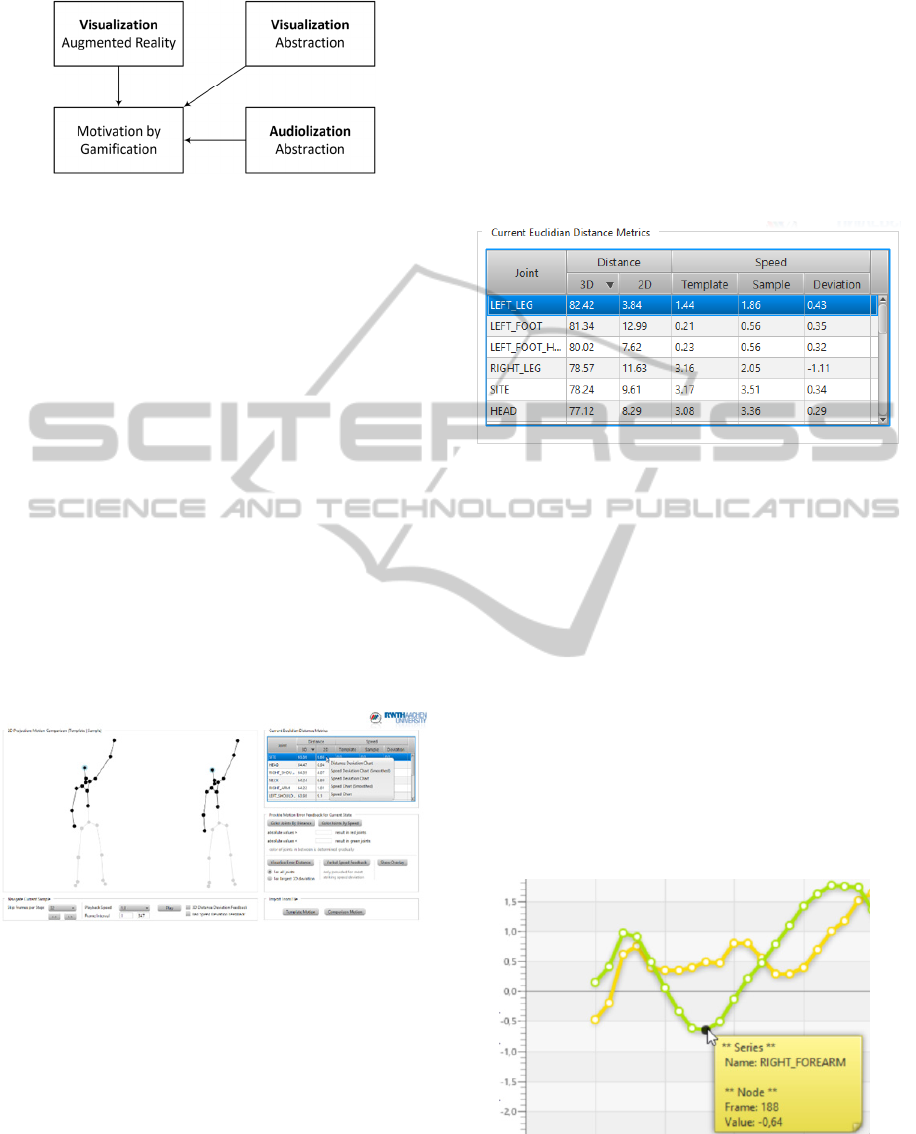
Figure 2: Possible ways for motion error feedback.
4 MOTION COACHING SYSTEM
To combine the ideas of motion errors and different
types of motion feedback, a prototype system was
implemented that enables first experiments with
some of the proposed feedback types.
JavaFX was used as an underlying framework
since it allows fast creation of user interfaces with
JavaFX Scene Builder and provides built-in support
for animations and charts. In order to enable concen-
trating on the visualization itself, the system takes
two synchronized motion sequence files as input.
Synchronized in this context means that frame num-
ber i in the template motion corresponds with frame
number i in the comparison motion. The contained
joint positions are normalized and allow to ignore
different physiques. Figure 3 provides an overview
of the system (joints that are not relevant for a spe-
cial motion can be de-selected manually).
Figure 3: Overview of the motion coaching system.
For testing purposes, sample data collected from
subjects performing a baseball pitching-motion were
used.
4.1 Feature Overview
Visual Output of Data I – Metrics (Textual): The
performance metrics illustrated in Figure 4 provide
basic information such as 3D and 2D distance devia-
tions per joint and a comparison of the template and
sample speed per joint. Due to the perspective pro-
jection of the real-world 3D coordinates to the joint
positions in the visualized 2D skeleton on the screen,
it may occur that there are large 3D deviations that
are not recognizable in the skeleton representation.
The data helps to get an understanding of this rela-
tion and allows for very detailed motion analysis.
Nevertheless, this high precision is not necessarily
needed for a motion coaching scenario and a subject
may only use this type for terminal or delayed feed-
back.
Figure 4: Distance and speed metrics for a single pair of
frames for currently loaded motion sequences.
Visual Output of Data II – Metrics (Graphical):
Charts are used to visualize distance and speed met-
rics over time. Multiple joints can be selected to be
included in a single chart to compare the respective
deviations. This allows for an extensive joint cluster-
ing analysis, e.g., for finding out which joints can be
clustered together as bodypart in order to provide
feedback on a per-bodypart instead of a per-joint
basis. From a motion coaching perspective, this type
of feedback is mainly suited for terminal or delayed
feedback. It is expected that the acceptance depends
on the subject’s spatial abilities. Figure 5 exemplary
visualizes the speed deviation (between the template
and comparison motion) of two different joints for a
small frame interval.
Figure 5: Speed deviation chart for right forearm (selected
series) and right hand.
As real world data is often subject to large fluctua-
tions, values are smoothed for visualization purposes
PhyCS2014-InternationalConferenceonPhysiologicalComputingSystems
170
by calculating a weighted average for the k-step
neighborhood (k between 5 and 10).
Visual Output of Data III – Colored Joint Over-
lay: The developed system allows to define a lower
and an upper threshold value. All joints with devia-
tions larger than the upper threshold value are col-
ored in red, all joints with deviations smaller than
the lower threshold value are colored in green (ap-
plicable for speed and distance deviations). The
coloring of joints with values in between those
thresholds is determined gradually (i.e. vary from
red over orange to green). An example can be found
in Figure 6 (left skeleton) where the largest devia-
tions occur for joints located on the right arm. This
visualization approach can be used either for concur-
rent, terminal or delayed feedback and allows to
easily determine joints with high deviations. Never-
theless, the determination of reasonable threshold
values over time is technically hard and no infor-
mation is given on how to correct the motion.
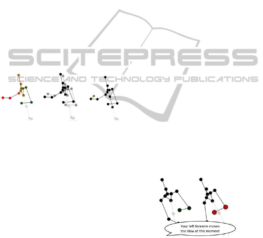
Figure 6: Exemplary skeleton-based distance error visuali-
zations (left: colored joint overlay, center: overlay of
template and comparison skeleton, right: static result of
animated joint moving to its correct position).
Visual Output of Data IV - Skeleton Overlay:
Visualizing the template and comparison skeleton in
an overlaid manner (instead of side by side, which is
the default behavior of the proposed system) turned
out to be only suitable to correct very small motion
errors. Otherwise the mapping between the intended
and actual joint position is not directly visible. Of-
ten, it is hard to differentiate between the two skele-
tons. To overcome this weakness, the opacity value
of the template is lower than the one of the compari-
son skeleton (see Figure 6, center).
Visual Output of Control - Distance Error Ani-
ma- tion: So far, no direct information on how to
correct the motion was given. The initial idea of
Velloso et al. (2013) that used directed arrows to
indicate how to correct the motion was adapted and
replaced by an animated joint that moves to its cor-
rect position and thereby gradually changes its color
from red (wrong position) to green (correct target
position is reached). Even though this is still a quite
technical representation, this approach is considered
to be more natural than the representation using
arrows (see Figure 6, right). Since the projected 2D
position difference does not automatically reflect the
3D position difference, it is expected that the success
of this method highly depends on the projection
parameters. It is only applicable for terminal or de-
layed feedback.
Auditory Output of Control - Speed Feedback:
To address more than one sense, auditory feedback
was included as well. For the most striking speed
deviation, a verbal feedback phrase is provided by
using a text-to-speech library. However, even if
humans are used to this type of auditory feedback,
such a specific per-joint feedback is not applicable
in practice. Therefore, several joints are clustered to
body parts and feedback is provided accordingly
(e.g. “Move your right arm faster” instead of “Move
your right elbow faster”). Auditory Feedback in
general is best suited for concurrent feedback. Speed
feedback in particular suffers from the fact that it is
too slow to convey feedback for very fast motions at
the correct moment.
Combination of Visual and Auditory Output of
Data: As stressed in the previous section, per joint
speed feedback is regarded as too technical. In this
approach that combines visual and auditory output,
joints are clustered to body parts (by using the charts
for analyzing deviation dependencies) and consid-
ered as a whole during motion error feedback. The
animated illustration is embedded in a video play-
back of the motion sequences (see Figure 7) and
supported by corresponding speech output. Note that
the coloring allows to easily determine the affected
body part and the blinking speed of the highlighted
joints depicts the type of speed deviation (too fast:
fast blinking, too slow: slow blinking).
Figure 7: Example for embedded multimodal speed feed-
back in motion sequence playback (Note: text in speech
bubble is provided by speech output and is not visualized).
4.2 Future Work
In a next step, an empirical analysis is required to
evaluate the effectiveness and acceptance of the
TowardsanAutomaticMotionCoachingSystem-FeedbackTechniquesforDifferentTypesofMotionErrors
171

different types of feedback. For this analysis, it is
important to consider several types of motions and
exercises and compare respective acceptance values.
To do so, the integration of an automatic determina-
tion of appropriate projection parameters is required.
Two of the proposed general feedback types (ab-
stracted visualization and abstracted audiolization)
were addressed in our prototype system. Additional-
ly, first analogue approaches by using an augmented
reality scenario should be anticipated. A last im-
portant research area to be worked on is the effect of
using sounds and changing its parameters for motion
error feedback.
5 DISCUSSION
This paper analyzed different ways to provide mo-
tion error feedback, a very specific aspect within the
development of an automatic motion coaching sys-
tem. This divide-and-conquer approach allowed us
to focus on feedback techniques itself without strug-
gling too much with implementation details that are
not directly relevant at this point. It is expect that the
results from this first prototype can be used for an
initial evaluation that may allow to exclude several
feedback possibilities or reveal the need for analyz-
ing others in more detail. However, technology ac-
ceptance is a quite complex phenomenon (Ziefle et
al., 2011) and the success of a motion coaching
system does not only depend on the visualization
alone. Consequently, final statements are only pos-
sible when a complete system has been developed
and tested in detail. The development of such a sys-
tem requires an interdisciplinary approach with
scientific contributions from the fields of machine
learning, computer vision, human-computer interac-
tion and psychology.
REFERENCES
Chatzitofis, A., Vretos, N., Zarpalas, D. & Daras, P., 2013.
Three-Dimensional Monitoring of Weightlifting for
Computer Assisted Training. In: Proc. of VRIC '13.
Chen, Y.-J. & Hung, Y.-C., 2010. Using Real-Time Ac-
celeration Data for Exercise Movement Training with
a Decision Tree Approach. In: Expert Systems with
Applications, 37(12), pp. 7552-7556.
Evans, C. & Palacios, L., 2010. Using Audio to Enhance
Learner Feedback. In: Proc. of ICEMT’10, pp. 148-
151.
Heidrich, F., Ziefle, M., Röcker, C. & Borchers, J., 2011.
Interacting with Smart Walls: A Multi-Dimensional
Analysis of Input Technologies for Augmented
Environments. In: Proc. AH'11, CD-ROM.
Kasugai, K., Ziefle, M., Röcker, C. & Russell, P., 2010.
Creating Spatio-Temporal Contiguities Between Real
and Virtual Rooms in an Assistive Living Environ-
ment. In: Proc. of Create’10, pp. 62 - 67.
Kelly, D., McDonald, J. & Markham, C., 2008. A System
for Teaching Sign Language Using Live Gesture
Feedback. In: Proc. of FG’08, pp. 1-2.
Klack, L., Kasugai, K., Schmitz-Rode, T., Röcker, C.,
Ziefle, M., Möllering, C., Jakobs, E.-M., Russell, P. &
Borchers, J., 2010. A Personal Assistance System for
Older Users with Chronic Heart Diseases. In: Proc. of
AAL'10, CD-ROM.
Lawrence, G. & Kingtson, K., 2008. Skill Acquisition for
Coaches. In: An Introduction to Sports Coaching:
from Science and Theory to Practice. New York
(USA): Routledge, pp. 16-27.
Matsumoto, M., Yano, H. & Iwata, H., 2007. Develop-
ment of a Motion Teaching System Using an Immer-
sive Projection Display and a Haptic Interface. In:
Proc. of WHC’07, pp. 298-303.
Miles, H. C., Pop, S., Watt, S. J., Lawrence, G. P. & John,
N. W., 2012. A Review of Virtual Environments for
Training in Ball Sports. In: Computers & Graphics,
36(6), pp. 714-726.
O'Sullivan, D. & Igoe, T., 2004. Physical Computing.
Boston, MA: Thomson Course Technology.
Röcker, C., 2013. Intelligent Environments as a Promising
Solution for Addressing Current Demographic Chang-
es. In: International Journal of Innovation, Manage-
ment and Technology, 4(1), pp. 76-79.
Spelmezan, D. & Borchers, J., 2008. Real-Time Snow-
board Training System. In: Extended Abstracts of
CHI’08, pp. 3327-3332.
Takahata, M., Shiraki, K., Sakane, Y. & Takebayashi, Y.,
2004. Sound Feedback for Powerful Karate Training.
In: Proc. of NIME’04, pp. 13-18.
Takano, K., Li, K. F. & Johnson, M. G., 2011. The Design
of a Web-Based Multimedia Sport Instructional Sys-
tem. In: Proc. of WAINA’11, pp. 650-657.
Velloso, E., Bulling, A. & Gellersen, H., 2013. Mo-
tionMA: Motion Modeling and Analysis by Demon-
stration. In: Proc. of CHI’13, pp. 1309-1318.
Ziefle, M., Röcker, C., Kasugai, K., Klack, L., Jakobs, E.-
M., Schmitz-Rode, T., Russell, P. & Borchers, J.,
2009. eHealth – Enhancing Mobility with Aging. In:
Proc. of AmI'09, pp. 25-28.
Ziefle, M., Röcker, C., Wilkowska, W., Kasugai, K.,
Klack, L., Möllering, C. & Beul, S., 2011. A Multi-
Disciplinary Approach to Ambient Assisted Living.
In: E-Health, Assistive Technologies and Applications
for Assisted Living: Challenges and Solutions. Niagara
Falls, NY: IGI Publishing, pp. 76-93.
PhyCS2014-InternationalConferenceonPhysiologicalComputingSystems
172
