
A Multimodal Low-cost Platform for Acquisition of Electrophysiological
Signals Interfacing with Portable Devices
A. Santos Ribeiro
1,2
, D. Salvado
2,3
, G. Evans
4
, J. Soares Augusto
5
and H. A. Ferreira
2
1
Centre for Neuropsychopharmacology, Division of Brain Sciences, Department of Medicine,
Imperial College London, London, U.K.
2
Institute of Biophysics and Biomedical Engineering, Faculty of Sciences, University of Lisbon, Lisbon, Portugal
3
Institute of Nuclear Medicine, University College London, London, U.K.
4
Centro de F
´
ısica da Mat
´
eria Condensada, Faculty of Sciences, University of Lisbon, Lisbon, Portugal
5
Instituto de Engenharia de Sistemas e Computadores: Investigac¸
˜
ao e Desenvolvimento, Lisbon, Portugal
Keywords:
Multimodal Acquisition, Physiological Signals, Arduino, Mobile, Low-Cost.
Abstract:
Advances in low-voltage integrated circuits have enabled the development of low-cost, low-power, and down-
sized portable instrumentation. In the biomedical field, mobile sensing platforms provide an efficient way to
monitor the physical condition of a subject. Moreover, these platforms provide an input for human-computer
interaction. We developed a low-cost platform that can be adapted to acquire different electrophysiological
signals, and interface with portable devices for storing, processing, and displaying of data. The developed
platform was used to acquire electrocardiography (ECG), electromyography (EMG), electroencephalography
(EEG), and electrooculography (EOG) signals, and the results were compared with signals obtained with the
benchmark BIOPAC system. For the same frequency bands, results show that our portable platform was able
to acquire electrophysiological signals with similar accuracy as those acquired with the BIOPAC system. Due
to its simplicity, low-cost design, and easy implementation, the developed platform suits researchers, devel-
opers, and hobbyists, in the fields of physiological monitoring, human-computer interaction, and perceptual
computing.
1 INTRODUCTION
Recent advances in the miniaturization and availabil-
ity of portable biomedical devices have shown to im-
prove healthcare quality (West, 2012). The appli-
cation of mobile health monitoring systems in am-
bulatory, emergency, home, and point-of-care set-
tings provide a greater access to physiological data,
leading to improved therapeutic decision-support, and
decision-making. Similarly, rehabilitation procedures
(Bin Ambar, 2012)(Roy, 2009), physiology-driven
robotics (Yin et al., 2012), and human-computer in-
teraction (Zheng, 2009)(Kim, 2004)(Andreoni et al.,
2007) should benefit from the use of portable biomed-
ical devices. The wide range of applications promotes
further research in the area of system design and con-
trol for increased reliability, multimodality integra-
tion, and easy implementation and dissemination.
Most of commercially available biomedical
portable devices are dedicated systems and usually
focus on only one kind of electrophysiological sig-
nal (e.g. (Emotiv, 2013)(Alive Technologies, 2013)).
Although beneficial, the use of such devices is con-
fined to specific tasks and applications. On the other
hand, multimodal acquisition systems on the mar-
ket (e.g. (PLUX wireless biosignals, 2013)(Shimmer,
2013)) are designed based on two components: (1)
a main unit for data storage, transmission, and pro-
cessing, and (2) dedicated sensors for the acquisi-
tion of specific electrophysiological signals. Either
single or multimodal approaches lead to unnecessary
costs, as in the first case a completely different plat-
form is needed for each electrophysiological signal
to be acquired, and in the second case, different sen-
sors are required. However most electrophysiological
signals require the same acquisition steps: differen-
tial amplification, filtering, and additional amplifica-
tion, depending on the target signal (Webster, 2010).
Therefore, a single customizable platform for the ac-
quisition of the different electrophysiological signals
would be desirable and more cost-effective.
This work illustrates the development and imple-
63
Santos Ribeiro A., Salvado D., Evans G., Soares Augusto J. and Ferreira H..
A Multimodal Low-cost Platform for Acquisition of Electrophysiological Signals Interfacing with Portable Devices.
DOI: 10.5220/0004885000630070
In Proceedings of the International Conference on Physiological Computing Systems (PhyCS-2014), pages 63-70
ISBN: 978-989-758-006-2
Copyright
c
2014 SCITEPRESS (Science and Technology Publications, Lda.)

mentation steps of a low-cost multimodal acquisition
platform, which interfaces with portable devices, such
as laptops, tablets or smartphones to collect, record,
process, and display electrophysiological data.
2 MATERIAL AND METHODS
The developed platform is comprised of three main
blocks: an analogue circuit, an Arduino MEGA ADK
board, and a mobile platform.
The analogue circuit was simulated in a general-
purpose circuit simulation program (B
2
Spice, Beige
Bag Software), and implemented in a printed circuit
board (PCB) using CadSoft EAGLE PCB design soft-
ware. This platform was then connected to the Ar-
duino MEGA ADK board, which was programmed to
collect the signal, and connect to the mobile platform
for data processing.
In this section, we will discuss in detail the stages
of circuit development and implementation, and the
interface with the Arduino and mobile platforms.
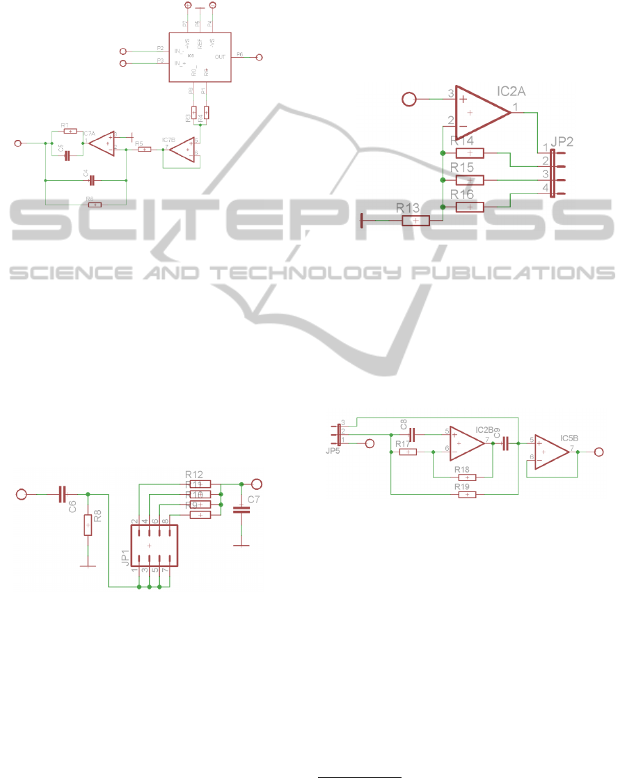
2.1 Analogue Circuit
The main analogue circuit is comprised of 8 sub-
circuits, Figure 1: electrical protection circuit; differ-
ential (1st stage) amplification with a Driven Right
Leg circuit (DRL); low-pass filter; 2nd stage amplifi-
cation; notch filter; high-pass filter; 3rd stage amplifi-
cation; and voltage offset circuit.
Protective
stage
Differential
amplification
with DRL
Drift removal
and low
pass filter
2nd stage
amplification
3rd stage
amplification and
voltage offset
High pass
filter
Notch filter
ADC and
USB
interface
Data collection,
visualisation,
and processing
TCP/IP
connection
with MATLAB
Figure 1: Pipeline of the developed multimodal acquisition
platform. Dark blue stages correspond to the analogue cir-
cuit, medium blue stages to the Arduino Mega ADK board,
and light blue stages to the mobile platform.
2.1.1 Circuit Development
The first sub-circuit (Figure 2) attenuates high fre-
quencies present in the acquired signal, using a pas-
sive low-pass filter. Such circuit aims to reduce the
radio-frequency (RF) noise induced in the cables, and
its propagation from the electrodes to the analogue
circuit. Additionally, this sub-circuit protects the user
against electrical shock (high voltage) by means of
two inverted diodes. Diodes are analogue components
that only allow the passage of signal if the signal goes
in the diode forward direction and if there is a differ-
ential potential over 0.7V at the diode terminals. Us-
ing this configuration, signals over +0.7V and under
-0.7V flow directly to ground, while signals within
these limits are not affected. Note that this is a re-
dundant protective stage, and that the user should not
be at any time connected directly to the main power
supply. For example, if the computer is connected to
the main power supply, and the acquisition platform is
connected to the computer, the user is also connected
to the main power supply. Thus there would be a high
risk of electrical shock in the presence of an electrical
discharge followed by failure of the protective circuit.
In this case, the main protective stage is therefore the
use of batteries in the acquisition device.
Figure 2: Protective sub-circuit and RF removal.
The sub-circuit following the protective stage cir-
cuit is responsible for the acquisition and amplifica-
tion of the low amplitude electrophysiological sig-
nals, which range from microvolts to millivolts (Fig-
ure 3). The typical design approach is to use an in-
strumentation amplifier (IA) that multiplies the dif-
ference between the two inputs, typically between
10 and 100, reducing the common-mode noise. For
this type of application, a low-noise, low-drift and
low-power consumption IA is required, such as the
INA114, which is widely applied in medical instru-
mentation (Burr-Brown Corporation, 1998). To im-
prove the common-mode noise rejection a driven-
right-leg (DRL) circuit may be used. In this system,
the ground electrode is connected through a feedback
loop to the IA, instead of directly to the reference in-
PhyCS2014-InternationalConferenceonPhysiologicalComputingSystems
64
put of the IA. This circuit feeds the user with a small
current that is the inverse of the common-mode noise
(obtained from the IA), therefore reducing the overall
noise.
Figure 3: Differential amplifier sub-circuit with DRL feed-
back.
Although the chosen IA has low drift voltage
(50µV maximum for the INA114), this offset may
still lead to the circuit malfunction after the amplifica-
tion blocks. For example, in a typical EEG board, an
amplification between 1000 and 100000 is required,
therefore the offset is amplified from 50µV to 5V .
To account for this effect, a passive high-pass filter
(HPF) with a very low cut-off frequency can be used,
blocking continuous current while allowing variable
current to pass. Next to this circuit, a low-pass fil-
ter (LPF) transparent to the frequencies below the fre-
quencies of interest is used (Figure 4).
Figure 4: Offset removal and LPF with variable cut-off fre-
quency sub-circuits.
As the frequencies of interest vary with the tar-
get electrophysiological signal (Table 1), a four-
input one-output switch was used for the purpose of
achieving multimodality. Hence either electrocardio-
graphy (ECG), electromyography (EMG), electroen-
cephalography (EEG) or electrooculography (EOG)
signals can be recorded adjusting the values of the re-
sistors, in order to change the value of the LPF cut-off
frequencies.
As the filtered signal still has a very low ampli-
tude, a second amplification stage is needed (Figure
5). For the same reasoning used for the LPF, a four-
input one-output switch was used to increase differ-
ently the amplitude of the signal according to the elec-
trophysiological signal of interest. For example, the
EEG signal has a very low amplitude and will need
higher amplification when compared to an ECG sig-
nal, which can have an amplitude 1000 times higher
(Table 1).
Figure 5: Variable second stage amplification sub-circuit.
The next circuit module is an active notch-filter
(NF), designed to attenuate the electric grid noise at
50/60 Hz
1
. For this purpose, a band-stop filter centred
at 50Hz was implemented according to the schematic
in Figure 6. As the main hub noise has frequencies
in the range of those of electrophysiological signals, a
switch was implemented to turn on and off the notch
filter, depending on the application.
Figure 6: Main hub (50Hz) notch filter sub-circuit.
At this stage, the acquired signal has already been
filtered for low-frequencies and main hub noise, as
well as amplified. Yet, an HPF is required to reduce
the noise which has frequencies above the frequen-
cies of interest. For the purpose of generalization and
customization, the HPF was also adapted for different
inputs (Figure 7).
Although the analogue signal could already be
passed to a microprocessor for analog-to-digital con-
version (ADC), and passed to a mobile device or lap-
top via USB or Bluetooth connection, programming a
microprocessor is not straightforward. An easy way
to do it is to use an Arduino platform, which is our
purpose. Therefore two final analogue steps are re-
quired to use the Arduino board (Figure 8). Firstly,
1
EU and US mains frequency, respectively.
AMultimodalLow-costPlatformforAcquisitionofElectrophysiologicalSignalsInterfacingwithPortableDevices
65
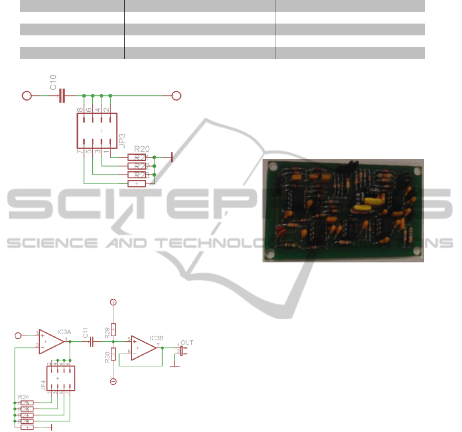
Table 1: Frequency and amplitude ranges for ECG, EMG, EEG, and EOG(National Instruments, 2013).
Signal Frequency range (Hz) Amplitude range (mV)
ECG 0.01 − 300 0.05 − 3
EMG 50 − 3000 0.001 − 100
EEG 0.1 − 100 0.001 − 1
EOG 0.1 − 10 0.001 − 0.3
Figure 7: High-pass filter with variable cut-off frequency
sub-circuit.
a third amplification stage is required to increase the
signal amplitude of the acquired signals to the 0-5V
interval, specially for the EEG signal. Secondly, a
voltage offset circuit is required to translate the signal
to positive voltages only.
Figure 8: Third stage amplifier and voltage offset sub-
circuits.
2.1.2 PCB Implementation
After having the circuit design completed, tested, and
simulated, it was implemented in a printed circuit
board (PCB). The main issue in this stage is to oc-
cupy the least possible space and avoid acute angles
- to reduce induced noise -, whilst trying to have few
crossing connections. Therefore the components are
placed in the board and organised in a way such that
connections between components have the shortest
length possible. Ground connections were performed
with a polygon instead of lines, such as to reduce the
overall noise (by increasing the ground area). The fi-
nal manufactured board has 52mm height and 92mm
width.
In the developed board (Figure 9) a two-layer PCB
was implemented. This configuration was chosen be-
cause it is the standard used by many PCB manufac-
tures, and therefore reduces costs of production.
Figure 9: Multimodal electrophysiological signal acquisi-
tion PCB board (with components). The board has 52mm
height and 92mm width, and two layers.
2.2 Arduino Platform
The analogue board was connected to an Arduino
MEGA ADK platform in order to use its ADC. The
Arduino MEGA ADK board has 54 digital input/out-
put pins, of which 15 can be used as Pulse Width
Modulation (PWM) outputs, 16 analogue inputs, 4
UARTs (hardware serial ports), a 16MHz crystal os-
cillator, and a USB connection. It has a 10-bit resolu-
tion, and is able to acquire analogue signals at a maxi-
mum sampling frequency of 10kHz, therefore suitable
for handling biomedical data.
Due to the high number of analogue inputs, the
Arduino platform can be easily set up for additional
acquisition boards, i.e. channels; this improves the
customization of the device, and facilitates the inte-
gration of different platforms.
The USB host interface given by MAX3421E IC
allows the connection, and subsequent interaction, of
the Arduino board with any type of device that has
a USB port. For example, it may be used to interact
with many types of phones, control Canon cameras,
or interface with keyboards, mouses and games con-
trollers as the Wii remote and PS3 controller.
The Arduino programming language is an imple-
mentation of Wiring, a similar physical computing
PhyCS2014-InternationalConferenceonPhysiologicalComputingSystems
66

platform, which is based on the Processing multi-
media programming environment. Arduino programs
are written in C/C++. The Arduino IDE comes with
the software library Wiring from the original Wiring
project (Wiring, 2013), which makes many common
input/output operations easier. To make a runnable
cyclic executive program developers only need de-
fine two functions: setup() - a function run once at
the start of a program that can initialize settings; and
loop() - a function called repeatedly until the board
powers off.
2.3 Mobile Platform
To communicate with the Arduino board, a desktop
computer or mobile platform can be used. The in-
terface is programmed such as to receive the digital
signal from the Arduino via microUSB connection,
and to store the data either in a desktop hard disk,
or in a mobile internal disk or SDcard. In a typical
laptop-Arduino connection, high level programming
languages (e.g. MATLAB) can be used to decrease
programming hassle. This becomes even more impor-
tant as more complex applications are needed, such as
real-time processing or visualization.
The ability to interface with mobile platforms
brings full portability to the acquisition device, yet
usually at the expense of more complex program-
ming software. On the other hand, high level pro-
gramming languages, e.g. Octave and MATLAB, and
typical desktop operating systems (OS), e.g. Linux,
are also being implemented in mobile platforms due
to their increased processing capabilities. These ad-
vances open new possibilities of mobile communica-
tion for users with low programming skills, and for
the development of general applications, opposed to
OS-specific applications.
Based on these ideas, a mobile communication
script was developed to store the data acquired with
the Arduino platform in the mobile platform, to be
further processed and visualized with the GNU Oc-
tave application, or with MATLAB via computer with
a TCP/IP connection. It is important to note that cur-
rently there is no direct communication from the Ar-
duino platform to the mobile Octave application, and
the mobile MATLAB software only works through
cloud computing. An example of communication
from the Arduino platform to MATLAB is presented
below.
1 uns ign ed l on g t i m e ;
2 i n t s e n s o r V a l u e ;
3 i n t po s ;
4
5 vo i d e s t a b l i s h C o n t a c t ( ) {
6 w h i l e ( S e r i a l . a v a i l a b l e ( ) <= 0) {
7 S e r i a l . p r i n t l n ( ’A’ ) ;
8 d e l a y ( 3 0 0 ) ;
9 }
10 }
11
12 vo i d s e t u p ( ) {
13 S e r i a l . b e g i n ( 1 1 5 2 0 0 ) ;
14 e s t a b l i s h C o n t a c t ( ) ;
15 }
16
17 vo i d l o o p ( ) {
18 t i m e = m i l l i s ( ) ;
19 S e r i a l . p r i n t ( t i m e ) ;
20 f o r ( pos =0 ; pos <10; p os ++) {
21 S e r i a l . p r i n t ( ’ , ’ ) ;
22 s e n s o r V a l u e = a n al o g R e ad ( A0 ) ;
23 S e r i a l . p r i n t ( s e n s o r V a l u e ) ;
24 }
25 S e r i a l . p r i n t l n ( ’ , ’ ) ;
26 }
arduino code.c
1 s 1 = s e r i a l ( ’COM# ’ ) ;
2 s 1 . B audR ate = 1 15 20 0;
3 s e t ( s1 , ’ t e r m i n a t o r ’ , ’LF ’ ) ;
4 f op en ( s1 ) ;
5
6 w= ’B ’ ;
7 w h i l e w˜= ’A’
8 w= f s c a n f ( s1 , ’%s ’ ) ;
9 f p r i n t f ( s1 , ’%s \n ’ , ’A ’ ) ;
10 end
11
12 a c q t i m e = z e r o s ( 1 , 1 0 0 0 0 0 0 ) ;
13 a c q d a t a = z e r o s ( 1 , 1 0 0 0 0 0 0 ) ;
14 p os =1 ;
15 w h i l e 1
16 s i z = 1 0 ;
17 r a w d a t a = f s c a n f ( s1 ) ;
18 d e l i m i t e r = ’ , ’ ;
19 r a w d a t a = t e x t s c a n ( r a w d a t a , ’%d
’ , ’ d e l i m i t e r ’ , d e l i m i t e r ) ;
20 r a w d a t a = d o u b l e ( r a w d a t a { 1 }) ;
21 a c q d a t a ( ( pos −1)∗ s i z + 1 : po s ∗ s i z ) =
a l l d a t a ( 2 : s i z +1 ) ∗ 5 / 1 0 2 4 ;
22 a c q t i m e ( pos ) = a l l d a t a ( 1 ) ;
23 pos = p os +1 ;
24 end
25 f c l o s e ( s 1 ) ;
matlab code.m
AMultimodalLow-costPlatformforAcquisitionofElectrophysiologicalSignalsInterfacingwithPortableDevices
67
2.4 Set-up
The developed platform was used to acquire: a lead I
ECG; an EMG of the brachioradialis muscle contrac-
tion; an EEG of the occipital cortex; and an EOG of
the horizontal direction for a reading task. Recorded
signals were then compared to the corresponding sig-
nals obtained with the commercially available bench-
mark BIOPAC system to evaluate the performance of
the developed platform. All acquisitions were per-
formed with one channel - three electrodes: positive,
negative and reference. The platform was supplied
with a dual voltage source of 9V. In addition, the high-
pass and low-pass filters’ cut-off frequencies and am-
plification gains were adjusted to those of interest for
acquiring ECG, EEG, EMG, and EOG signals (Web-
ster, 2010).
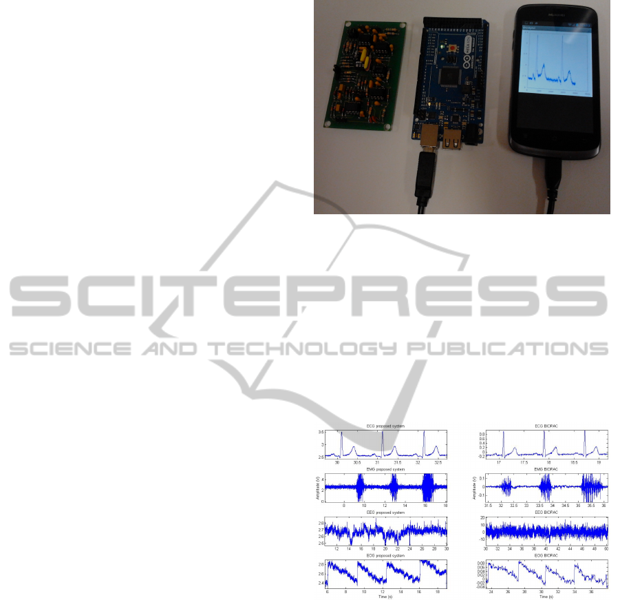
3 RESULTS
The multimodal platform is shown in Figure 10. The
communication of the analogue circuit with the Ar-
duino Mega ADK platform was performed through
jumper cables (not shown in Figure 10). Other inter-
face options could have been implemented, such as
adapting the analogue circuit into an Arduino shield.
Such approaches are easily implemented as both plat-
forms have roughly the same size. Further considera-
tions have been made to implement the proposed plat-
form through surface-mount technology to decrease
size or to provide additional channels within the same
size. Although such approach is highly recommended
in commercial devices it may impair the implementa-
tion for researchers and hobbyists with low practice
in soldering electronic circuits.
The communication of the Arduino with the mo-
bile platform is performed through a microUSB ca-
ble. This approach leads to simpler hardware and
software implementation. A wireless communication
between the two could be implemented without hav-
ing to re-design the analogue circuit: one could com-
bine a Bluetooth shield with the Arduino platform.
The acquired ECG, EMG, EEG, and EOG signals
obtained with the developed acquisition platform are
shown in Figure 11 (left) as well as the correspond-
ing signals obtained with the BIOPAC system (right).
The cut-off frequencies of the low-pass (fcLP) and
high-pass (fcHP) filters were adjusted, respectively,
to fcLP = 116, 248, 116, 48 Hz and fcHP = 0.04, 16,
0.16, 0.05 Hz. For the BIOPAC platform the cut-off
frequencies of the LPF and HPF were selected, re-
spectively, to fcLP = 100, 250, 100, 30 Hz and fcHP
= 0.05, 30, 0.5, 0.05 Hz. Results show that the differ-
Figure 10: Developed multimodal acquisition platform.
From left to right: Analogue board, Arduino MEGA ADK
and mobile platform (connections between the Analogue
board and the Arduino MEGA ADK, and battery power
supply not shown for clarity).
ent signals present similar traces for both acquisition
platforms. Moreover a higher signal-to-noise ratio is
observed for the ECG signal of the proposed system
when compared to the BIOPAC platform, while for
the EMG and EOG a lower signal-to-noise ratio is
verified.
Figure 11: Acquired signals. ECG (first row), EMG (sec-
ond row), EEG (third row) and EOG (fourth row) signals
acquired by the developed platform (left) and the BIOPAC
system (right).
An estimation of the cost of the proposed proto-
type is presented in Table 2, for a 1- and 4-channel
acquisition platform. The predicted cost for both
the single, and multichannel acquisition platform is
≤ 250e, thus presenting a low-cost approach to mul-
timodal acquisition systems. Note that the price does
not scale linearly with the number of channels, even
for prototyping, because of the fact that one Arduino
Mega ADK is able to simultaneously acquire up to 16
channels, requiring no additional boards, and a higher
number of PCB boards is cheaper.
These results suggest that accurate and low-cost
PhyCS2014-InternationalConferenceonPhysiologicalComputingSystems
68

Table 2: Approximated cost estimation for a 1- and 4-channel acquisition board in euros (e).
Component 1-channel acquisition board 4-channel acquisition board
Instrumentation amplifier (INA114AP) 10e 40e
Other through hole components 15e 60e
PCB Board 35e 100e
Arduino Mega ADK 50e 50e
Total 110e 250e
multimodal solutions can be developed for biomed-
ical signal acquisition, without requiring expertise
in both electronics and programming. As previ-
ously suggested, some enhancements of this plat-
form can be performed to increase robustness, reli-
ability, and portability, making this system useful for
advanced biomedical applications at the expense of
higher knowledge of electronics and programming.
4 CONCLUSIONS
A low-cost, simple and easy to implement portable
multimodal acquisition platform was developed using
an analogue circuit, an Arduino MEGA ADK and a
mobile platform. The developed platform was able to
acquire different electrophysiological signals, such as
ECG, EMG, EEG, and EOG, by changing the low-
pass and high pass filters’ cut-off frequencies and am-
plification gain.
Two further developments to increase portability
and usability of the acquisition platform were fore-
seen. Firstly, the modification of the design of the
analogue platform in order to use it as an Arduino
shield. This modification allows the user to add ex-
tra analogue acquisition platforms, up to 15 additional
boards for the Arduino Mega ADK, such that different
electrophysiological signals can be acquired simulta-
neously (e.g. 16 EEG channels, or 8 EEG channels
+ 8 EMG channels). Secondly, the replacement of
manual switching to digital switching. Such conver-
sion allows the user to digitally control the acquisition
parameters without physical interaction, allowing for
the abstraction of the electronics, and enhancing us-
ability.
The developed platform is ideal for researchers,
developers and hobbyists, as it is portable, low-cost,
easily adaptable to acquire various physiological sig-
nals, and scalable/customizable in order to acquire a
larger number of channels. Due to its characteristics,
the developed platform is suitable for application de-
velopment in the fields of physiological monitoring,
human-computer interaction, and perceptual comput-
ing.
ACKNOWLEDGEMENTS
Research supported by Fundao para a Ciłncia e
Tecnologia (FCT) and Ministrio da Ciłncia e Edu-
cao (MCE) Portugal (PIDDAC) under grant PEst-
OE/SAU/UI0645/2011.
REFERENCES
Alive Technologies (2013). Alive website.
http://www.alivetec.com/.
Andreoni, G., Parini, S., Maggi, L., Piccini, L., Panfili, G.,
and Torricelli, A. (2007). Human machine interface
for healthcare and rehabilitation. In Vaidya, S., Jain,
L., and Yoshida, H., editors, Advanced Computational
Intelligence Paradigms in Healthcare-2, volume 65
of Studies in Computational Intelligence, pages 131–
150. Springer Berlin Heidelberg.
Bin Ambar, R. (2012). Multi-sensor arm rehabilitation
monitoring device. Biomedical Engineering, Interna-
tional Conference on, pages 424–429.
Burr-Brown Corporation (1998). BB INA114 Precision In-
strumentation Amplifier Datasheet.
Emotiv (2013). Emotiv website. http://www.emotiv.com/.
Kim, J. (2004). A new means of HCI: EMG-MOUSE, Sys-
tems, Man and Cybernetics. IEEE International Con-
ference on, 1:100–104.
National Instruments (2013). Biomedical engineer-
ing education portal. http://www.ni.com/white-
paper/5593/en/.
PLUX wireless biosignals (2013). Plux website.
http://www.plux.info/.
Roy, S. (2009). A Combined sEMG and Accelerometer
System for Monitoring Functional Activity in Stroke.
IEEE Transactions on Neural Systems and Rehabili-
tation Engineering, 17:585–594.
Shimmer (2013). Shimmer website. http://www.shimmer-
research.com/.
Webster, J., editor (2010). Medical Instrumentation Appli-
cation and Design. John Wiley & sons.
West, D. (2012). How Mobile Devices are Transforming
Healthcare. Issues in Technology Innovation, no.18:1–
14.
Wiring (2013). Wiring framework website.
http://wiring.org.co/.
AMultimodalLow-costPlatformforAcquisitionofElectrophysiologicalSignalsInterfacingwithPortableDevices
69

Yin, Y., Fan, Y., and Xu, L. (2012). Emg and epp-integrated
human-machine interface between the paralyzed and
rehabilitation exoskeleton. Information Technology in
Biomedicine, IEEE Transactions on, 16(4):542–549.
Zheng, X. (2009). A portable wireless eye movement-
controlled Human-Computer Interface for the dis-
abled. International Conference on Complex Medical
Engineering, pages 1–5.
PhyCS2014-InternationalConferenceonPhysiologicalComputingSystems
70
