
Embodied Localization in Visually-guided Walk of Humanoid Robots
Hendry Ferreira Chame and Christine Chevallereau
Robotics Team of the IRCCyN, Ecole Centrale de Nantes, CNRS, Nantes, France
Keywords:
Humanoid Robotics, Embodied Cognition, Ego-localization, Machine Vision.
Abstract:
Humanoid robots are conceived to resemble the body and comportment of the human beings. Among the
behavior repertoire, the possibility of executing visually-guided tasks is crucial for individual adaptation and
relies on the on-board sensory system. However, the research on walk and localization is far from conclusive.
Given the difficulties in the processing of the visual feedback, some studies have treated the problem by
placing external sensors on the environment; thus neglecting the corporal metaphor. Others, despite exploring
on-board solutions; have relied on an extensive model of the environment, thus considering the system as an
information processing unit, abstracted from a body. This work presents a methodology to achieve embodied
localization to serve visually-guided walk. The solution leans on robust segmentation from monocular vision,
ego-cylindrical localization, and minimal knowledge about stimuli in the environment.
1 INTRODUCTION
Humanoid robots are conceived to resemble the body
and the comportment of the human beings. Among
the behavior repertoire, the possibility of executing
visually-guided tasks is crucial for individual adapta-
tion and relies on the on-board sensory system. How-
ever, the research on walk and localization is far from
conclusive. When using vision, estimates on local-
ization strongly depend on the quality of the object
tracking process. Given the differences between the
human and the artificial vision system, the recogni-
tion (or segmentation) of stimuli on the scene can
be difficult; and different approaches are available.
Furthermore, an interesting debate has been taking
place on the way to represent the relation between
the agent’s posture, the objects’ posture, and the de-
sired locations in space. Traditional approaches has
considered solutions where the agent is conceived as
an information processing unit, in a decoupled Carte-
sianist mind-body view; where intelligent behavior
is regarded as a symbolic manipulation process from
actual sensory input (Shapiro, 2007). Recently, sub-
jectivity in being considered in a more Heideggerian
sense, where agency and interactive coping occupy
center stage (Anderson, 2003). Such as, real-world
thinking occurs in particular situations, and is em-
ployed for specific practical ends. Thereby, cognition
is viewed as embodied or within a situated activity.
Starting from the notion of embodiment, the ob-
jective of this work is to explore the possibilities of
designing solutions to the problem of visually-guided
positioning in relation to stimuli on the environment.
Thus, a methodology that leans on robust segmen-
tation from monocular vision will be reported. The
solution proposes ego-cylindrical localization, requir-
ing of minimal knowledge about stimuli. The sections
of this paper are organized as follows. Section 2 ex-
plores related works in the field of on-board localiza-
tion. Given the difficulties of object tracking, Section
3 introduces the problem of image processing by ex-
ploring some techniques to achieve robust segmenta-
tion. The Markov Random Field (MRF) formalism
will be discussed in more detail, due to the good re-
sults it provides on image segmentation. Section 4
formalizes the localization task via a case study. Sec-
tion 5 presents the results obtained. Finally, conclu-
sions and research perspectives are presented.
2 RELATED WORK
On-board visual localization relies on robust object
tracking, which is a challenging task for walking
robots. Indeed, certain difficulties have been reported
when attempting to make use of the captured images,
since walk introduces motion blur noise. Some stud-
ies have treated the problem by placing the visual sys-
tem on the environment (e.g., (Lewis M.A. and Simo
L.S., 1999)). Though, occlusions may compromise
165
Ferreira Chame H. and Chevallereau C..
Embodied Localization in Visually-guided Walk of Humanoid Robots.
DOI: 10.5220/0005063001650174
In Proceedings of the 11th International Conference on Informatics in Control, Automation and Robotics (ICINCO-2014), pages 165-174
ISBN: 978-989-758-040-6
Copyright
c
2014 SCITEPRESS (Science and Technology Publications, Lda.)

the localization given the robot’s motions. Alterna-
tives include estimates in position through other sen-
sor modalities like external microphones, which cap-
ture the robot’s intrinsic noise (Allen et al., 2012).
Unfortunately, the location of stimuli and the robot
in relation to the sensors may also compromise the
results. Furthermore, the orientation component can-
not be estimated in this way. In general, exteroceptive
solutions neglect the corporal metaphor, impose the
condition that the environment must be adapted to the
problem, and are very sensitive to modeling impreci-
sions.
When considering on-board solutions, the limited
control over the head’s direction and its effect over
the visual output, has complicated the task (Michel
et al., 2005). To treat this problem, the compensation
for the head’s motion by taking advantage of the kine-
matic and geometric models of the robot has been at-
tempted; such as, a virtual camera has been defined to
cancel the sway motion in the visual features for con-
tinuous visual servoing (Dune et al., 2010). Though,
considerable delays may be involved in the vision pro-
cessing; due to digital image treatment and video data
transference from the on-board camera to the com-
puter system (Moughlbay et al., 2013). These delays
can restrict the applications of real-time visual servo-
ing techniques in closed-loop. Furthermore, physio-
logical evidence has also reported considerable delays
in the human visuo-motor loop (Miall et al., 1993).
The feedback is estimated to take around 130 ms for
ocular-motor control and 110-150 ms for propriocep-
tive control. According to these figures, the perfor-
mance observed in natural beings may be better ex-
plained by the organization and the efficiency in the
management of the available resources, rather than
by the computational power. In addition, continu-
ous visual control during walking may not be nec-
essary since depending on the walking stage, images
have greater or less relevance for the localization (the
head’s motion may produce blurred images at certain
points). So considerable processing overhead may be
added with little benefit for localization.
The task representation has also been a topic of in-
terest. The displacement to be accomplished has been
referenced within a global map; that the agent may
possess, update, or build while navigating. For exam-
ple, in a work developed by (Hornung et al., 2010),
the problem of indoor localization is tackled by adapt-
ing a range sensor to the robot’s head. The posture of
the robot is estimated within a known volumetric map
of the environment; such as, the on-board measure-
ments parametrize a probabilistic search routine. In a
work developed by (Robert Cupec, 2005), a global lo-
calization policy is combined with local references to
enhance the accuracy when stepping over small obsta-
cles. The strategy is based on an interesting method
for directing the gaze by maximizing the visual in-
formation; but evidences the limitations of the global
localization approach where the accuracy is greatly
affected and strongly depends on the quality of mod-
eling (including parameters estimation), and the noise
in the measurements. For both of these works, the
localization-and-locomotion task has been modeled
as a control problem, with the body playing the role of
a mere tool that has to be commanded appropriately
(Hoffmann and Pfeifer, 2012).
The discussion has exposed at this point some
important aspects about localization in humanoid
robotics. It has been assessed the reliability of the
on-board sensory to effectively accomplish the task,
given the noise introduced by motion. Furthermore,
the role of the agent in relation to the environment
has been investigated; in particular, the extent to
which the environment must be known or adapted to
the agent for the attainment of the localization task.
Lastly, the convenience of using a global reference
policy has been contrasted to locally referencing stim-
uli, in relation to the precision obtained for localiza-
tion. This research starts from the hypothesis that
on-board localization can be achieved by relying on
robust object segmentation, with minimal knowledge
about the environment, and defining a sensory ego-
centric reference system. In the following, these as-
pects will be discussed.
3 IMAGE SEGMENTATION
Image segmentation and object tracking are hard pro-
cesses to achieve. In the literature, a huge number
of techniques are available, where each one imposes
certain constraints. An in-deep treatment of the topic
cannot be accomplished here; thus, some of the ex-
plored proposals that showed good results are going
to be briefly discussed.
The first approach considered was the classical k-
means algorithm (MacQueen, 1967), which is a con-
venient technique to obtain clusters. The method is
not very efficient for real-time applications given its
high computational complexity ς = O(n
dk+1
log(n)),
for d dimension feature vectors, k clusters and n el-
ements (pixels in the case of images). Also, k is re-
quired which significantly constraints the characteris-
tics of the images to be treated. The expectation max-
imization (EM) algorithm (Dempster et al., 1977) is
more efficient and general, in the sense that the clus-
ters are represented by probability distributions and
not just by the means. Unfortunately, it also requires
ICINCO2014-11thInternationalConferenceonInformaticsinControl,AutomationandRobotics
166
of k as an input parameter.
Another technique explored was the continuously
adaptive mean shift (CAMShift) algorithm, which
performs color-based tracking. CAMShift essentially
climbs the gradient of a back-projected probability
distribution from a color histogram, and finds the
nearest peak within a search window. When the cam-
era is fixed, the algorithm offers reasonably good re-
sults. However, for on-board tracking, the motions of
the camera affect the color distribution of the object
since variations in the point of view result in changes
in illumination; which degrades the obtained segmen-
tation. Improvements have been proposed by (Exner
et al., 2010) and consist in the accumulation of multi-
ple histograms.
As alternative to color-based tracking, feature-
based techniques have also been explored. The dif-
ferential Lucas-Kanade method (Lucas and Kanade,
1981) estimates the optical flow by using a least
squares criterion. The algorithm assumes brightness
constancy, spatial coherence, and small displacement
of the features between frames (high frame rate). The
last requirement makes the technique unsuited to sys-
tems operating at low frequencies, so the tracking
may be lost due to the constrained local search.
Some techniques have focused, by other hand, on
the pre-processing of the image to reduce the motion
blurs introduced by the walk (Pretto et al., 2009). The
observed image b(x, y) = h(x, y) ∗ f (x,y) + n(x, y) is
the result of the convolution operation of the a blur-
ring function h(x,y), also known as the point spread
function (PSF); over the original image f (x,y) and the
added noise n(x,y). The goal is to restore f (x,y) from
an estimation of h(x.y). Several techniques have been
proposed to deconvolve f (x,y) (e.g., the Richardson-
Lucy algorithm and Wiener filter). Unfortunately, it is
not so simple to estimate the PSF for random motions,
and the quality of the results strongly depend on it.
In general, for most of the techniques discussed,
the elements under analysis have been individual pix-
els of the image; which becomes a main drawback
in the presence of noise. Spacial tracking techniques
generally aim to match points of interest in a sequence
of images; by assuming that the time interval between
frames is small enough to perform a local search at
low computational cost (generally around a neighbor-
hood). Unfortunately, to ensure real-time responsive-
ness; the calculation of the features tend to be simple
in order to be fast. This conditions the robustness un-
der disturbances like the motion blurs. Besides, simi-
larly to the delays observed in natural beings; certain
platforms (e.g. the Nao robot) cannot afford a high
frame-rate to satisfy the tracking conditions.
3.1 Markof Random Fields (MRF)
An alternative to spacial tracking is to assume no rela-
tion between successive images; such as, the segmen-
tation can be achieved by only relying on the color
model of the object. The MRF formalism considers
the spacial coherence between regions of pixels on the
image; it is an interesting approach to obtain robust
segmentation and is going to be discussed here.
The observed image F = { f
s
| s ∈ I} consists of
the spectral component values registered in a color-
space η at which each pixel s is denoted by the vector
f
s
. The label of interest
ˆ
ϕ is the one that maximizes
the a posteriori probability P(ϕ | F):
argmax
ϕ∈Φ
∏
s∈I
P( f
s
| ϕ
s
)P(ϕ), (1)
where Φ denotes the set of all possible labellings.
Since the goal is to segment the image into homo-
geneous regions, a pixel class λ should correspond to
one or more homogeneous color patches in the input
image. Such regularities can be modeled by an addi-
tive white noise with covariance Σ
λ
centered around
the expected color value µ
λ
. Thus, P( f
s
| ϕ
s
) fol-
lows a Gaussian distribution and pixel classes λ ∈ Λ =
{1,2,...L} are represented by the mean vectors µ
λ
and
the covariance matrices Σ
λ
. Furthermore, P(ϕ) is a
MRF with respect to a first order neighborhood sys-
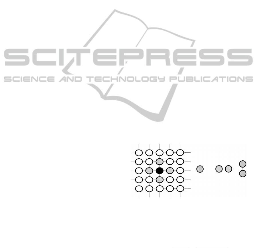
tem (as shown in Fig. 1).
First-order neighborhood
Cliques
Figure 1: First-order neighborhood system. Single pixel
cliques are called singletons, horizontal and vertical cliques
are called doubletons (Kato et al., 2001).
According to the Hammersley-Clifford theorem,
P(∗) follows a Gibbs distribution:
P(ϕ) =
e
−U (ϕ)
Z(γ)
=
∏
c∈C
e
−V
c
(ϕ
c
)
Z(γ)
, (2)
where U(ϕ) is called an energy function, Z(γ) =
∑
ϕ∈Φ
e
−U (ϕ)
is the normalizing constant (or partition
function) and V
c
denotes the clique potential of clique
c ∈ C having the label configuration ϕ
c
. C is the set
of spatial second order cliques (i.e., doubletons). The
EmbodiedLocalizationinVisually-guidedWalkofHumanoidRobots
167
energies of singletons directly reflect the probabilis-
tic modeling of labels without context, while double-
ton clique potentials express the relationship between
neighboring pixel labels. The energy function de-
noted on the MRF image segmentation model, as pro-
posed by (Kato et al., 2001); has the following form:
U(ϕ,F) =
∑
s∈I
(ln(g) +
k
2
) + β
∑
{s,r}∈C
δ(ϕ
s
,ϕ
r
), (3)
where g =
p
(2π)
3
|Σ
ϕ
s
|, k = ( f
s
− µ
ϕ
s
)Σ
ϕ
s
−1
( f
s
−
µ
ϕ
s
)
t
; and δ(ϕ
s
,ϕ
r
) = 1 if ϕ
s
6= ϕ
r
and zero other-
wise. The parameter β > 0 controls the homogene-
ity of the regions; as it increases, the regions become
more homogeneous. The function U(ϕ,F) is non-
convex, so the convergence to the global optimum
cannot be ensured since the calculation of Z(γ) in (2)
is intractable. In practice, combinatorial optimization
techniques such as iterated conditional modes (ICM)
(Besag, 1986) are employed to achieve the segmenta-
tion. The next state
ˆ
ϕ
k+1
s
is determined by
ˆ
ϕ
k+1
s
← arg min
ϕ
s∈{1,...,L}
U(
ˆ
ϕ
k
,F). (4)
The stop condition is attained when
ˆ
ϕ
k+1
s
=
ˆ
ϕ
k
s
,∀s. (5)
To summarize, the parameters of the system are
Θ = (µ
λ
,Σ
λ
,β). In case when Θ is provided by the
user, a supervised segmentation is obtained. Other-
wise, Θ must be automatically estimated simultane-
ously to ϕ, which is known as unsupervised segmen-
tation. For the later case, the role of the parameter β
may vary in time, as pointed out by (Deng and Clausi,
2004).
4 ON-BOARD LOCALIZATION
The object is assumed to be previously known with
its dimension. The robot has to localize it, thus the
relation in position and orientation with respect to the
robot has to be defined. The parameters Θ = (ξ,ψ) of
the system are the geometrical properties of the object
ξ, and its color model ψ.
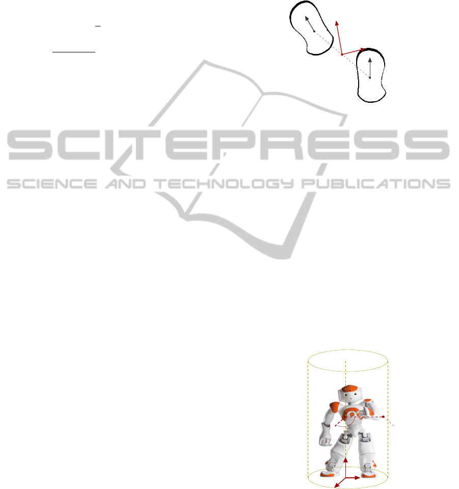
4.1 Sensory Ego-cylinder
The robot is assumed to be walking on a plane, such
as the movable frame B is fixed to the ground. The
origin of the frame corresponds to the intermediate
point between the center of projection of both feet on
the ground (see Fig. 2). Analogously, B
x
is the mean
direction between the major orientation axis of each
foot. The axis B
z
is chosen to be perpendicular to the
ground plane, and B
y
⊥ B
x
.
Base frame
F
l
F
r
B
z
y
x
Figure 2: Representation of the base frame B.
The concept of ego-sphere, as presented in
(Bodiroza et al., 2011), is an interesting proposal to
express the ego-localization of the saliency of stimuli
on the environment. Although, the cylindrical geom-
etry seems to be more appealing to our case, given
that it is simpler and convenient to represent the posi-
tions of objects moving on a plane. Thus, we employ
an ego-cylinder principle for localization (as shown
in Fig. 3). In relation to the orientation component,
only the azimuth φ around B
z
can be corrected by the
walk primitives of the robot; so the ego-cylinder is
extended to include the magnitude of φ as follows
P =
ρ θ z φ
t
. (6)
Ego-Cylinder
B
y
x
z
φ
P
θ
ρ
Figure 3: Representation of the ego-cylinder localization.
In the image, B corresponds to the base frame, and P repre-
sents the localization of an object in the environment. The
magnitude of the rotation φ around B
z
is represented by the
direction emerging from the cylinder’s surface.
ICINCO2014-11thInternationalConferenceonInformaticsinControl,AutomationandRobotics
168

4.2 Localization
The localization of the object in the scene is based on
the definition of four frames, as depicted in Fig. 4.
The pose P of the object can be known with respect to
the base frame B through the definition of the homo-
geneous transformation matrix
B
T
O
=
B
T
H
(q)
H
T
C
C
T
O
, (7)
where the transformation
B
T
H
(q) expresses the head
frame H in the base frame B, and depends on the
actual joint configuration q of the robot. The trans-
formation
H
T
C
is constant and expresses the camera
frame C in frame H. The transformation
C
T
O
ex-
presses the object frame O in frame C, and is deter-
mined from the 3D pose
C
O =
ζ ω
t
=
x y z
γ β θ
t
, (8)
where ζ is the position component and ω is the orien-
tation component. The calculation of
C
O depends on
the geometry of the object model, some examples are
given as case studies in Section 4.4.
Task Frames
B
H
C
O
Figure 4: Definition of the reference frames to solve the
localization task. In the image, B corresponds to the base
frame, H to the head frame, C to the camera frame, and O
to the object frame.
The transformation
B
T
O
allows the definition of
the localization of the object in the ego-cylinder by
expressing the position of the center of frame O in
cylindrical coordinates, and adding the orientation φ
of the object around B
z
as defined in (6).
4.3 Visually-guided Walk
Since the base frame B is mobile, the transformation
B
T
B
∗
between its current location and the desired lo-
cation B
∗
in relation to the object is given by
B
T
B
∗
=
B
T
O
O
T
B
∗
, (9)
where the transformation
O
T
B
∗
is defined by demon-
stration. In other words, by placing the robot at the
desired pose in relation to the object.
A difference in location
B
d between the current
and the desired configuration, presents the same struc-
ture of (6), and is obtained from
B
T
B
∗
. The first three
components are determined by expressing the posi-
tion component of the transformation in cylindrical
coordinates; whereas the four coordinate is extracted
from the rotational component of
B
T
B
∗
and corre-
sponds to the rotation around B
z
. A direction of mo-
tion
¯
M can be determined from
B
d as follows
B
¯
M = sat(
B
d,λ), (10)
where sat is a saturation function for the position and
orientation components of
B
d, and λ are the corre-
sponding thresholds.
4.4 Case Studies
Object localization based on visual tracking, is greatly
dependent on the quality of the segmentation pro-
cess. If the later is successful, simpler geometrical
models are enough to accomplish the task. Thus, in-
stead of fitting rich 3D meshes to images (such as in
(Legrand et al., 2002)); simple geometrical contain-
ers were considered as models. The idea behind this
philosophy is defining reusable models acting as ori-
ented wrappers to objects of potential interest on the
scene. Next, the modeling of two of these contain-
ers and how to estimate them from the image blob is
going to be detailed.
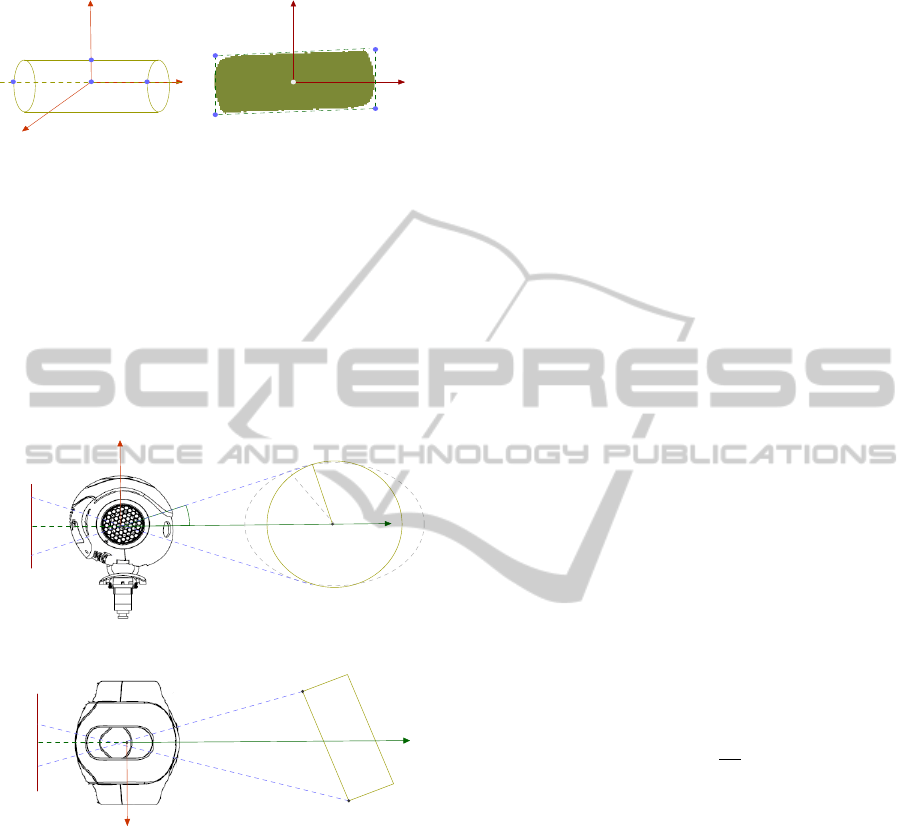
4.4.1 Cylindrical Wrapper
The frame O is attached to the center of mass of the
model as shown in Fig. 5. As a result,
C
O in (8) is
estimated. Given the symmetry of the shape, the pro-
jection of the object in the image plane is not affected
by the rotation β around O
y
; so it is assumed to be
constant.
Depth Estimation. The blob is approximately cen-
tered on the image to avoid calculations over a clipped
projection of the object. In order to estimate the posi-
tion of frame O (as illustrated in Fig. 6); the depth of
L and R with respect to the frame C must be calculated
through the function
d(r, r
0
, f ) =
s
r
sin(γ)
2
+ r
2
, (11)
where r is the radius of the cylinder, r
0
is its projection
on the image plane, γ = atan2(r
0
, f ), and f is the fo-
cal length of the camera.
C
L
z
and
C
R
z
are calculated
EmbodiedLocalizationinVisually-guidedWalkofHumanoidRobots
169
Object Frame
Z
Y
X
L R
O
U
Segmented Image
Y
i
X
i
O
0
G
0
H
0
J
0
K
0
Figure 5: Definition of the cylindrical object model. On the
left, the 3D representation of the object frame O and the
definition of four points of interest. On the right, the illus-
tration of the segmented blob and the definition of image
features from the oriented bounding box.
by tacking r
0
to be |G
0
−K
0
|/2 and |H
0
−J
0
|/2 respec-
tively. The analytical expression will be exact if the
orientation component
C
O
θ
= 0 in (8); otherwise in-
accuracy will be introduced.
Image Plane
Object’s pose estimation
2r
0
f
d
Y
r
O
α
(a)
Image Plane
X
L
R
(b)
Figure 6: Estimation of the object’s depth. a) The model
assumes
C
P
φ
= 0, b) XZ visualization of the scenario where
the circumference corresponds to an ellipse and the distance
from the projective ray and the center O is larger than r.
Position Estimation. The position of a 3D point X
in frame C can be calculated by the definition of the
projective function
C
X = p(X
z
,X
0
,C
0
, f ), such as
p(X
z
,X
0
,C
0
, f ) =
((X
0
x
−C
0
x
)X
z
)/ f
((X
0
y
−C
0
y
)X
z
)/ f
X
z
. (12)
Where X
0
is the projection of X in the image plane,
and C
0
is the image center. Thus, the position compo-
nent
C
O
ζ
in (8) is given by
C
O
ζ
=
M
x
M
y
M
z
+ r
t
, (13)
where M = mean(
C
L,
C
R). The other features of the
object model are calculated using (12) such as
C
L
C
R
C
U
=
p(
C
L
z
,mean(G
0
,K
0
),C
0
, f )
p(
C
R
z
,mean(H
0
,J
0
),C
0
, f )
p(
C
O
z
,mean(G
0
,H
0
),C
0
, f )
. (14)
Orientation Estimation. The orientation compo-
nent
C
O
ω
in (8) is obtained from the relation between
C
R,
C
L,
C
U, and
C
O. It is extracted from the rotation
matrix
C
R =
s n a
=
ˆ
H
ˆ
V (
ˆ
H ×
ˆ
V )
, (15)
with
ˆ
H = (
C
R −
C
L)/|
C
R −
C
L|, and
ˆ
V = (
C
U −
C
O)/|
C
U −
C
O|.
4.4.2 Rectangular Surface
Rectangles are useful geometric models for tracking
surfaces in walls, doors and furnitures (e.g., drawers).
The model is simpler than the previous one, since the
vertical axis O
z
is assumed to be perpendicular to the
ground. The points defining O correspond to those of
Fig. 5, except that R and L are now contained in the
ZY plane. The features tracked in the image are also
similar to the prior case. However, the calculation for
the depth of O changes to be given by
d(h,h
0
, f ) =
h f
h
0
, (16)
where f is the focal distance of the camera, h is half
of the height of the rectangle, and h
0
is the image pro-
jection of h. The relation between the image features
and the location of
C
R,
C
L, and
C
U is similar to the
previous case; though,
C
O = mean(
C
L,
C
R).
5 RESULTS
The study has been conducted in three stages. At first,
several segmentation algorithms were explored to as-
sess the robustness against the motions of the camera.
Next, a localization task has been simulated to opti-
mize the development of the algorithms and to detect
errors. Lastly, after obtaining a stable and correct ex-
ecution, the program has been evaluated in the experi-
mental platform. In the following, the results obtained
at each of these stages will be reported.
ICINCO2014-11thInternationalConferenceonInformaticsinControl,AutomationandRobotics
170
5.1 The Object Tracking Algorithm
The object tracking program was implemented in the
C++ language and included the OpenCV 2.4.8 library.
The routine presented the structure shown in Algo-
rithm 1. In relation to (3), the initializeColorModel
method estimates the statistical parameters (µ and Σ)
of the color model from a region labeled by the user.
No color model is required for the background, since
the appearance of new objects in the scene would af-
fect the tracking. Given the variations in lighting,
n sampled frames are averaged to reduce the noise
(usually n = 10 gives good results); and then pro-
vided to the initialization routine. The objectIsCen-
tered method rotates the head until the segmented
blob is approximately centered on the image. Once
accomplished, doFeatureExtration calculates the ob-
ject’s pose in the camera frame C.
Algorithm 1: Object Tracking.
1: procedure DOTRACKING
2: initializeColorModel()
3: while run do
4: while ob jectIsCentered() = f alse do
5: doSegmentation()
6: doFeatureExtration()
The segmentation routine consisted in a cus-
tomization of the MRF supervised technique (see Al-
gorithm 2). The algorithm possesses a computational
complexity ς = O(n
|Φ|
), where n is the number of s
pixels of the image I, as described in Section 3.1.
Since the problem was to recognize the object from
the background, |Φ| = 2. In addition, the images were
processed in the YUV color-space, thus, |η| = 3. The
localEnergy function corresponds to (3) with the dif-
ference that it is calculated with the color model of the
object (without the background model as explained
before). The initialize method proposes an initial seg-
mentation candidate
ˆ
ϕ by minimizing the singleton
term
∑
s∈S
(ln(g) +
k
2
). The evaluation of the segmen-
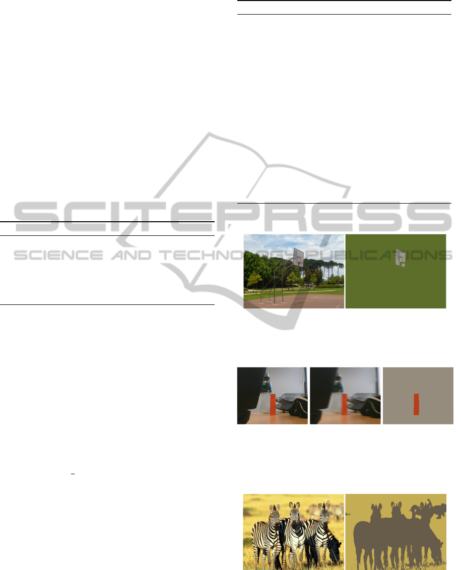
tation algorithm has shown that, for naturally illumi-
nated scenes (see Fig. 7), it is quite robust under cam-
era motions when detecting colored objects with dif-
fuse, non-specular reflective textures (as illustrated in
Fig. 8). The objects don’t have to possess uniform
or single colors as depicted in Fig. 9. For the case
of artificially illuminated scenes, in particular, under
low-frequency lighting; more samplings may be re-
quired to estimate the color model.
Algorithm 2: Segmentation.
1: procedure DOSEGMENTATION
2:
ˆ
ϕ(i, j) ← Initialize() Singleton initialization
3: e
Old
← 0
4: repeat
5: e ← 0
6: for i = 0 → i < height do
7: min
e
← localEnergy(i, j,
ˆ
ϕ(i, j))
8: for j = 0 → j < width do
9: for λ = 0 → λ < |Φ| do
10: c
e
← localEnergy(i, j,λ) current
energy
11: if c
e
< min
e
then
12:
ˆ
ϕ(i, j) ← λ
13: min
e
← c
e
14: e ← e + min
e
15: ∆e ← abs(e
Old
− e)
16: e
Old
← e stop when the change is too small
17: until ∆e > t
Segmentation of a natural scene
Figure 7: Segmentation of a natural scene. On the left, the
original image where a color sample was taken from the
white backboard. On the right, the segmentation achieved.
Segmentation under camera motions
Figure 8: Segmentation under camera motions. On the left,
the still image of the scene. In the center, a random motion
was applied to the camera. On the right, the segmentation
obtained.
Segmentation of colored objects
Figure 9: Segmentation of colored objects. On the left, the
original image of a group of zebras. On the right, the seg-
mentation achieved.
EmbodiedLocalizationinVisually-guidedWalkofHumanoidRobots
171
5.2 The Simulation Environment
The designed methodology can serve at two distinct
objectives. The first one is a typical information-
processing scenario, that employs the egocentric lo-
calization to guide the robot to relative coordinates in
the scene (e.g., requiring it to be at 20 cm in front of
the object). The precision of this task will be affected
by the errors introduced in the image projection, and
the approximations of the object model. The second
one is to show the robot, by demonstration, how it has
to be placed with respect to the target, such as, the
perception would be embodied. Here, it is not so im-
portant the absolute precision of the estimates, but the
the way the robot perceives its body in relation to the
stimulous.
In order to assess the performance under the im-
precisions described; a simulated environment has
been designed in Webots 7.0.4. In the conceived sce-
nario, the object of interest corresponded to a red soda
can placed over a table (as illustrated in Fig. 10). The
desired configuration
B
∗
T
O
was specified by position-
ing the robot in front of the can with its body oriented
at φ ≈ π with respect to it.
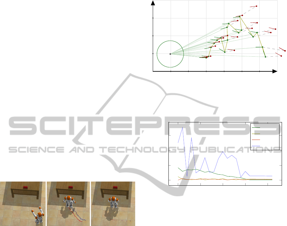
The simulated scene
Figure 10: The approach task modeled in Webots. On the
left, the robot’s original pose. In the center, the followed
trajectory. On the right, the desired pose with respect to the
red can on the table. As it can be seen, despite the modeling
errors, the robot was able to converge to a location very
similar to the demonstrated one.
For testing the localization task, since the walk
routines cannot act on the z component of (10); the
motion vector
B
M
0
= [M
ρ
,M
θ
,M
φ
]
t
was given as the
direction of displacement to the robot’s walk primi-
tive. No trajectory generation nor control was con-
sidered. Figure 11 illustrates the evolution of the lo-
calization along the followed trajectory. Figure 12
compares the on-board estimations with the measure-
ments provided by Webots. Despite the initial estima-
tions are not very precise, as the robot approached the
target, the precision increased enough to allow it to
convergence to the desired pose.
Egocentric trajectory evolution
0.0 0.2 0.4
0.6
0.8 1.0
0.0
0.2
0.4
x
y
Figure 11: XY egocentric visualization of the localization
as perceived in B. The circumference represents the ego-
cylinder. In red the real values, in green the estimations.
Distances are expressed in m.
0
5
10
15
20
0
0.2
0.4
0.6
Time step
Error
Localization Error
|ρ
e
− ρ
m
|
|θ
e
− θ
m
|
|z
e
− z
m
|
|φ
e
− φ
m
|
Figure 12: Evolution of the localization error between the
estimations e and the measurements m.
5.3 The Experimental Environment
In the experimental task the robot was placed in an
unstructured scene (the robotic lab). It was required to
approach a planar yellow rectangle (whose model was
detailed in Section 4.4.2); to a relative pose captured
by demonstration. As depicted in Fig.13, there are
different sorts of colored stimuli on the environment.
Despite this variability, the robot was able to converge
to the desired pose.
6 CONCLUSIONS AND FUTURE
WORK
This study has explored the possibility of obtain-
ing embodied visual localization to serve humanoid
robotics walk. For this purpose, a method based on
monocular vision was developed. Given the noise in
the on-board measurements, the research proposed to
verify that a sequential look-then-move policy would
ICINCO2014-11thInternationalConferenceonInformaticsinControl,AutomationandRobotics
172
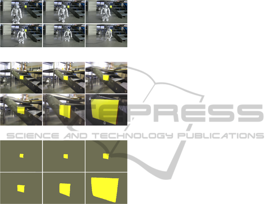
The experimental scene
(a)
(b)
(c)
Figure 13: The experimental environment. a) The scene
captured from an external camera, b) The on-board view, c)
The segmentations obtained.
be sufficient to perform the task; such as, computa-
tional efforts could be invested in the achievement of
robust object recognition. In this sense, the MRF for-
malism proved to be a convenient framework to define
the problem of color-based, supervised, image seg-
mentation under motion noise. The ego-localization
representation involved the definition of a percep-
tive ego-cylinder. Case studies has been proposed
to illustrate the philosophy behind the methodology,
and consisted in the definition of simple and reusable
models to wrap objects in the environment. Simula-
tions and experimentations were conducted and have
shown that, despite the simplicity of the models and
the perturbations involved, the robot was able to con-
verge to a desired pose in relation to the object by
relying exclusively on local estimates. The results ob-
tained addressed the benefits of embodiment for per-
ception and cognition in robotics, as compared to the
information-processing paradigm.
On-going efforts are aiming at including a top-
down feature attention mechanism for assisting track-
ing when objects leave the field of vision. Futher-
more, the error in position and orientation was in-
dependently regulated, thus resulting in holonomic
motions. The obtained trajectories can be improved
by defining a non-holonomic, ego-centric, trajectory
generation policy; which is currently under study and
will endorse the agent with a more human walk style.
ACKNOWLEDGEMENTS
This research has been funded by the Ecole Centrale
de Nantes; and the CAPES Foundation, Ministry of
Education of Brazil, Braslia - DF 700040-020, Brazil.
REFERENCES
Allen, B. F., Picon, F., Dalibard, S., Magnenat-Thalmann,
N., and Thalmann, D. (2012). Localizing a mobile
robot with intrinsic noise. In 3DTV-Conference: The
True Vision - Capture, Transmission and Display of
3D Video (3DTV-CON), 2012, pages 1–4.
Anderson, M. (2003). Embodied cognition: A field guide.
Artificial Intelligence, 149(1):91–130.
Besag, J. (1986). On the Statistical Analysis of Dirty Pic-
tures. Journal of the Royal Statistical Society. Series
B (Methodological), 48(3):259–302.
Bodiroza, S., Schillaci, G., and Hafner, V. (2011). Robot
ego-sphere: An approach for saliency detection and
attention manipulation in humanoid robots for intu-
itive interaction. In 2011 11th IEEE-RAS Interna-
tional Conference on Humanoid Robots (Humanoids),
pages 689–694.
Dempster, A. P., Laird, N. M., and Rubin, D. B. (1977).
Maximum likelihood from incomplete data via the em
algorithm. JOURNAL OF THE ROYAL STATISTICAL
SOCIETY, SERIES B, 39(1):1–38.
Deng, H. and Clausi, D. (2004). Unsupervised image seg-
mentation using a simple MRF model with a new im-
plementation scheme. In Proceedings of the 17th In-
ternational Conference on Pattern Recognition, 2004.
ICPR 2004, volume 2, pages 691–694 Vol.2.
Dune, C., Herdt, A., Stasse, O., Wieber, P. B., Yokoi,
K., and Yoshida, E. (2010). Cancelling the sway
motion of dynamic walking in visual servoing. In
2010 IEEE/RSJ International Conference on Intelli-
gent Robots and Systems (IROS), pages 3175–3180.
Exner, D., Bruns, E., Kurz, D., Grundhofer, A., and Bim-
ber, O. (2010). Fast and robust CAMShift track-
ing. In 2010 IEEE Computer Society Conference on
Computer Vision and Pattern Recognition Workshops
(CVPRW), pages 9–16.
EmbodiedLocalizationinVisually-guidedWalkofHumanoidRobots
173

Hoffmann, M. and Pfeifer, R. (2012). The implications of
embodiment for behavior and cognition: animal and
robotic case studies. CoRR, abs/1202.0440.
Hornung, A., Wurm, K., and Bennewitz, M. (2010). Hu-
manoid robot localization in complex indoor environ-
ments. In Intelligent Robots and Systems (IROS), 2010
IEEE/RSJ International Conference on, pages 1690–
1695.
Kato, Z., Pong, T.-C., and Chung-Mong Lee, J. (2001).
Color image segmentation and parameter estimation
in a markovian framework. Pattern Recognition Let-
ters, 22(34):309–321.
Legrand, L., Bordier, C., Lalande, A., Walker, P., Brunotte,
F., and Quantin, C. (2002). Magnetic resonance im-
age segmentation and heart motion tracking with an
active mesh based system. In Computers in Cardiol-
ogy, 2002, pages 177–180.
Lewis M.A. and Simo L.S. (1999). Elegant stepping: A
model of visually triggered gait adaptation. Connec-
tion Science, 11(3-4):331–344.
Lucas, B. D. and Kanade, T. (1981). An iterative image
registration technique with an application to stereo vi-
sion. In Proceedings of the 7th International Joint
Conference on Artificial Intelligence - Volume 2, IJ-
CAI’81, pages 674–679, San Francisco, CA, USA.
Morgan Kaufmann Publishers Inc.
MacQueen, J. (1967). Some methods for classification and
analysis of multivariate observations. In Proceed-
ings of the Fifth Berkeley Symposium on Mathemat-
ical Statistics and Probability, Volume 1: Statistics,
pages 281–297, Berkeley, Calif. University of Cali-
fornia Press.
Miall, R. C., Weir, D. J., Wolpert, D. M., and Stein, J. F.
(1993). Is the cerebellum a smith predictor? Journal
of motor behavior, 25(3):203–216. PMID: 12581990.
Michel, P., Chestnutt, J., Kuffner, J., and Kanade, T. (2005).
Vision-guided humanoid footstep planning for dy-
namic environments. In Proceedings of the IEEE-RAS
Conference on Humanoid Robots (Humanoids’05),
pages 13 – 18.
Moughlbay, A., Cervera, E., and Martinet, P. (2013). Model
based visual servoing tasks with an autonomous hu-
manoid robot. In Lee, S., Yoon, K.-J., and Lee, J.,
editors, Frontiers of Intelligent Autonomous Systems,
volume 466 of Studies in Computational Intelligence,
pages 149–162. Springer Berlin Heidelberg.
Pretto, A., Menegatti, E., Bennewitz, M., Burgard, W., and
Pagello, E. (2009). A visual odometry framework
robust to motion blur. In Robotics and Automation,
2009. ICRA ’09. IEEE International Conference on,
pages 2250–2257.
Robert Cupec, G. S. (2005). Vision-guided walking in a
structured indoor scenario. Automatika, 46(12):49–
57.
Shapiro, L. (2007). The embodied cognition research pro-
gramme. Philosophy Compass, 2(2):338–346.
ICINCO2014-11thInternationalConferenceonInformaticsinControl,AutomationandRobotics
174
