
Application of Artificial Neural Network State Feedback Controller
to Torque Ripple Minimization of PMSM
L. Niewiara
1
, T. Tarczewski
1
and L. M. Grzesiak
2
1
Institute of Physics, Faculty of Physics, Astronomy and Informatics, Nicolaus Copernicus University,
Grudziadzka 5, Torun, Poland
2
Institute of Control and Industrial Electronics, Warsaw University of Technology, Koszykowa 75, Warsaw, Poland
Keywords:
Artificial Neural Network, Adaptive State Feedback Controller, Permanent Magnet Synchronous Motor,
Torque Ripple.
Abstract:
This paper deals with the problem of torque ripple minimization of permanent magnet synchronous motor. The
novelty of the presented approach lays in precisely maintain the level of the voltage source inverter DC voltage
demanded for proper operation of the motor. An additional voltage matching circuit with state feedback
controller is introduced in order to control of the inverter DC voltage. In the proposed solution model of
a plant (i.e. permanent magnet synchronous motor fed by voltage source inverter with additional voltage
matching circuit) is non-linear and non-stationary. An adaptive state feedback controller is developed by
using an artificial neural network, which approximates non-linear control gain surfaces. A simple adaptation
algorithm based on 2 low-order low-pass filters is used. Simulation results illustrate the proposed approach in
comparison to typical drive with voltage source inverter and stationary state feedback controller.
1 INTRODUCTION
Minimization of torque ripple is an important re-
quirement in a wide range of high performance mo-
tion control applications with permanent magnet syn-
chronous motor (PMSM) such as robots, machine
tools and satellite trackers (Jahns and Soong, 1996).
The torque ripple generates unwanted mechanical vi-
bration (Gulez et al., 2008) and deteriorates perfor-
mance of the drive (Hasanien, 2010).
The torque ripple minimization can be realized by
using complex control techniques: preprogrammed
current waveforms for harmonics cancellation (Hung
and Ding, 1993), iterative learning control (Qian
et al., 2004), based on complex model of PMSM
adaptive control (Petrovic et al., 2000). On the
other hand an additional passive filter can be used to
produce sinusoidal output waveform of the inverter
(Steinke, 1999), (Kojima et al., 2004), (Tarczewski
and Grzesiak, 2013).
A new approach to the torque ripple minimiza-
tion is proposed in this paper. An additional volt-
age matching circuit (VMC) with state feedback con-
troller is used to precisely control of the voltage
source inverter (VSI) DC voltage required to proper
operation of the drive. A simple adaptation algorithm
is used to determine an appropriate value of DC volt-
age. In the proposed solution model of a plant (i.e.
PMSM fed by VSI + VMC) is non-linear and non-
stationary. In this field, an interesting solution can be
obtained when state feedback controller is used (Tar-
czewski et al., 2014). Non-linear control gain sur-
faces obtained for state feedback controller of PMSM
are implemented by using artificial neural network
(ANN) thanks to its universal approximation property
(Ferrari and Stengel, 2005), (Huang and Tan, 2012).
The efficacy of the torque ripple reduction and dy-
namic properties of the control system are confirmed
in a simulation study. Dynamic properties as well as
torque ripple factor calculated for proposed control
system are compared with values obtained for control
system with stationary state feedback controller and
PMSM fed by typical VSI.
2 MATHEMATICAL MODEL OF
THE SYSTEM
Considered control system consists of PMSM fed by
a 2-level VSI extended with voltage matching cir-
cuit. An additional buck converter (figure 1) was in-
363
Niewiara L., Tarczewski T. and Grzesiak L..
Application of Artificial Neural Network State Feedback Controller to Torque Ripple Minimization of PMSM.
DOI: 10.5220/0005086603630369
In Proceedings of the 11th International Conference on Informatics in Control, Automation and Robotics (ICINCO-2014), pages 363-369
ISBN: 978-989-758-039-0
Copyright
c
2014 SCITEPRESS (Science and Technology Publications, Lda.)

troduced to the inverter structure in order to realize
VMC. Block diagram of the proposed system is pre-
sented in figure 2.
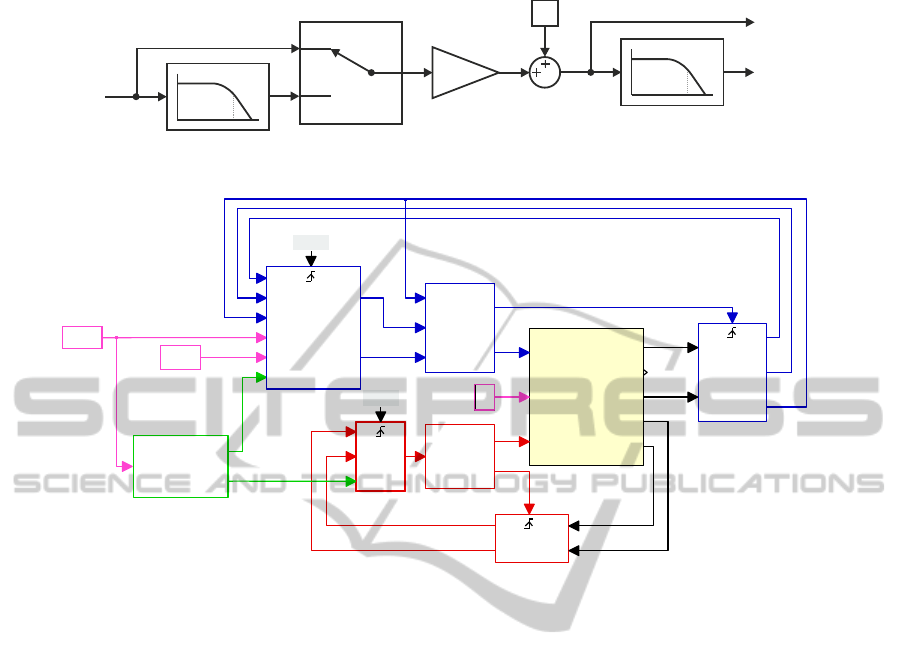
Figure 1: Topology of a buck converter.
PMSM
U
in
2-lev. inverter
u
C
i
s
ω
m
L
R
C
p
inv
i
sd ref
ω
m ref
neural
network
state
feedback
controller
i
L
p
conv
state
feedback
controller
adaptation
algorithm
K
p pmsm
K
p vmc
buck converter
Figure 2: Block diagram of the considered control system.
2.1 Model of the Buck Converter
State-space model of the proposed buck converter
with an output LC filter takes the following form:
dx
b
dt
= A
b
x
b
+ B
b
u
b
+ E
b
d
b
(1)
where:
x
b
=
"
i
L
u
C
#
, A
b
=
"
−
R
L
−
1
L
−
1
C
0
#
, B
b
=
"
Kpp
L
0
#
,
E
b
=
"
0
−
1
C
#
, u
b
= u
cc
, d
b
= i
o
i
L
- coil current, u
C
- capacitor voltage, R - coil resis-
tance, L - coil inductance, C - capacitor capacitance,
K
pp
- buck converter gain, u
cc
- input voltage, i
o
- load
current.
The buck converter was modeled by using propor-
tional element. Proposed approximation is valid for
sufficiency high switching frequency, omitted dead
time of power transistors and linear operation area of
the buck converter.
2.2 Model of the PMSM Fed by VSI
State-space model of the PMSM with VSI was written
in an orthogonal d, q coordinates system (Grzesiak
and Tarczewski, 2011):
dx
p
dt
= A
p
x
p
+ B
p
u
p
+ E
p
d
p
(2)
where:
A
p
=
−
R
s
L
s
pω
m
0
−pω
m
−
R
s
L
s
−
pΨ
f
L
s
0
3pΨ
f
2J
m
−
B
m
J
m
, B
p
=
K
p
L
s
0
0
K
p
L
s
0 0
,
E
p
=
0
0
−
1
J
m
, x
p
=
i
sd
i
sq
ω
m
, u
p
=
"
u
dc
u
qc
#
, d
p
= T
l
R
s
, L
s
- stator resistance and inductance, p - number
of pole pairs, ω
m
- rotor angular speed, Ψ
f
- PMSM
flux linkage, J
m
- moment of inertia, B
m
- viscous
friction, K
p
- variable VSI gain, i
sd
, i
sq
- space vec-
tor components of PMSM current, u
dc
, u
qc
- space
vector components of input voltage, T
l
- load torque.
It should be noted that in (2) a PMSM with surface
mounted magnets is taken into account. In such a
case inductances in d and q axis are in practical equal:
L
s
= L
d
= L
q
. Model of PMSM presented above is
non-linear and non-stationary due to the cross cou-
pling between space vector componentsof the PMSM
current as well as presence of the angular velocity in
a state matrix A
p
and variable VSI gain in an input
matrix B
p
.
3 CONTROL STRUCTURES
3.1 VMC Control Structure
A discrete state-feedback controller has been used in
order to precise control of the buck converter output
voltage. Gain values of the controller were deter-
mined with the help of the linear-quadratic optimiza-
tion method (Tewari, 2002). In order to control DC
voltage without steady-state error (in a case of step
variation of the reference voltage and the load cur-
rent) an internal model of the reference input was in-
troduced (Grzesiak and Tarczewski, 2013). After in-
troduction of an internal input model and assumption
that the load current is omitted an augmented state-
space model is:
dx
bi
dt
= A
bi
x
bi
+ B
bi
u
bi
+ F
bi
r
bi
(3)
where:
x
bi
=
i
L
u
C
e
u
, A
bi
=
−
R
L
−
1
L
0
−
1
C
0 0
0 1 0
, B
bi
=
Kpp
L
0
0
,
F
bi
=
0
0
−1
, u
bi
= u
b
, r
bi
= u
cref
ICINCO2014-11thInternationalConferenceonInformaticsinControl,AutomationandRobotics
364

u
cref
- reference value of the buck converter output
voltage. An additional state variable in (3) corre-
sponds to the integral of the buck converter output
voltage error:
e
u
(t) =
t
Z
0
[u
c
(τ) − u
cref
(τ)]dτ (4)
The following penalty matrices were used to deter-
mine gain values of the VMC controller:
Q
bi
= diag
1× 10
−3
4× 10
−3
3× 10
3
,
R
bi
= 1
(5)
Values (5) were selected empirically in order to:
provide zero steady-state buck converter output volt-
age error for a step change of the u
cref
as well as
for load current step variations; achieve maximum
permissible dynamics of VMC in the linear range of
modulation (at least 5 times faster than dynamics of
the PMSM).
Table 1: Basic parameters of VMC.
Parameter Value Unit
R 0.1 Ω
L 3 mH
C 30 µF
K
pp
600
Gain coefficients of the VMC controller calcu-
lated for system (3) with basic parameters given in
table 1 and for penalty matrices (5) are:
K
bi
=
0.129 0.049 40.595
(6)
3.2 PMSM Control Structure
Similar to VMC, control of the PMSM was realized
with the help of a discrete state-feedback controller.
Described type of control was chosen because of its
ability to control non-stationary systems (Tarczewski
et al., 2014). Note, that mathematical model of the
plant (i.e.PMSM fed by VSI) would be non-stationary
if VMC circuit is used. Because of presence of vari-
able parameters in a state matrix A
p
and input ma-
trix B
p
, the dimension of non-stationarity for PMSM
model (2) is 2.
As in a case of VMC control structure, an inter-
nal input models of the d axis reference current and
the reference angular velocity were added. An aug-
mented state-space model of the PMSM with VSI
takes the following form:
dx
pi
dt
= A
pi
x
pi
+ B
pi
u
pi
+ F
pi
r
pi
(7)
where:
A
pi
=
−
R
s
L
s
0 pω
m
0 0
0 1 0 0 0
−pω
m
0 −
R
s
L
s
−
pΨ
f
L
s
0
0 0
3pΨ
f
2J
m
−
B
m
J
m
0
0 0 0 1 0
, B
pi
=
K
p
L
s
0
0 0
0
K
p
L
s
0 0
0 0
,
x
pi
=
i
sd
e
i
i
sq
ω
m
e
ω
, F
pi
=
0 0
−1 0
0 0
0 0
0 −1
,
u
pi
= u
p
,
r
pi
=
"
i
sd ref
ω
mref
#
New state variables in a state vector x
pi
(i.e. e
i
and e
ω
)
correspond to the integral of the d axis current and the
angular velocity errors respectively:
e
i
(t) =
t
Z
0
i
sd
(τ) − i
sd ref
(τ)
dτ (8)
e
ω
(t) =
t
Z
0
[ω
m
(τ) − ω
mref
(τ)]dτ (9)
where: i
sd ref
- reference value of the d axis current,
ω
mref
- reference value of the angular velocity. An in-
ternal input models presented above were introduced
in order to provide zero steady-state error of the angu-
lar velocity and commonly used control strategy with
zero d axis current (Krishnan, 2010).
Because of non-stationarity of the model (7) gain
coefficients of the state feedback controller were ob-
tained at the operating points defined by the actual
value of:
• voltage source inverter’s gain K
p
∈ [10;300],
• PMSM’s angular velocity ω
m
∈ [−314;314] rad/s.
Steps of the VSI gain and PMSM angular veloc-
ity changes were chosen empirically: ∆ K
p
= 5,
∆ ω
m
= 2 rad/s. Linear-quadratic optimization
method was used to determine gain values of the con-
troller (Tewari, 2002). The following penalty matrices
has been chosen to determine variable gain values of
the controller:
Q
pi
= diag
q
pi1
q
pi2
q
pi3
q
pi4
q
pi5
q
pi6
,
R
pi
= diag([r
pi1
r
pi2
])
(10)
where: q
pi1
= 5.7× 10
1
, q
pi2
= 1× 10
7
, q
pi3
= 7.6×
10
−1
, q
pi4
= 1×10
−2
, q
pi6
= 1.68×10
2
, r
pi1
= r
pi2
=
3 × 10
−1
. Values (10) were selected empirically in
order to:
ApplicationofArtificialNeuralNetworkStateFeedbackControllertoTorqueRippleMinimizationofPMSM
365

50
100
150
200
250
-500
0
500
1000
2000
3000
K
p
k
d 1
pω
m
50
100
150
200
250
-500
0
500
-0.2
0
0.2
k
q 1
K
p
pω
m
50
100
150
200
250
-500
0
500
-1
0
1
k
d 5
K
p
pω
m
50
100
150
200
250
-500
0
500
0.5
1
1.5
pω
m
k
q 3
K
p
Figure 3: Examples of control gain surfaces.
• provide zero steady-state angular velocity error
for step change of angular velocity reference and
load torque step variations,
• achieve twice the rated current of PMSM
(i
sn
= 5.8A) during the step change of the ref-
erence angular velocity from 0 rad/s to 70π rad/s
with the rated load torque (T
ln
= 8.8Nm).
Assumptions presented above determine the maxi-
mum dynamics of the control system.
Table 2: Basic parameters of PMSM.
Parameter Value Unit
P
N
2.76 kW
R
s
1.05 Ω
I
N
5.8 A
L
s
9.5 mH
T
eN
8.8 Nm
K
t
1.64 Nm/A
Ω
mN
314 rad/s
K
e
98.84 V/1000
B
m
1.4× 10
−3
Nms/rad
p 3
J
m
6.2× 10
−4
kgm
2
For non-stationary system (7) with parameters
given in table 2 and penalty matrices (10) ten non-
linear control gain surfaces (CGS) have been con-
structed. Examples of CGS are presented in figure 3.
.
3.3 Artificial Neural Network
Controller
Since it is difficult to find the analytical formu-
las that accurately approximate non-linear CGS de-
scribed above, artificial neural network is employed in
the proposed intelligent controller. Due to the learn-
ing and approximating capabilities of the ANNs (Fer-
rari and Stengel, 2005), (Huang and Tan, 2012), the
designed neural network controller determines proper
gain values (i.e. 10 coefficients) depend on operating
point of the system.
It was found that CGS can be successfully approx-
imated with the help of the feedforward back prop-
agation neural network with 40 neurons in the first
layer and 10 neurons in the output layer. Satisfactory
level of the approximation (mean square error less
than 1× 10
−7
) was achieved after 383 iterations. Sig-
moidal functions were used as the activation functions
in the first layer, while linear functions were used in
the output layer.
3.4 Adaptation Algorithm
A simple adaptation algorithm presented in (Tar-
czewski et al., 2014) was used to determine an ap-
propriate gain values of the buck converter and of
the VSI. The reference value of the angular velocity
ω
mref
has been used as an input variable.
It was found that proper values of K
pvmc
and
K
p pmsm
can be obtained when two low-pass filters
with selector are used. The first one (2
nd
order low-
pass with a cutoff frequency f
c1
= 20.8Hz) is used to
ICINCO2014-11thInternationalConferenceonInformaticsinControl,AutomationandRobotics
366
1 low-pass filter
st
Selector
Gain
Bias
Δ ω| | 0
m ref
≥
Δ ω| | < 0
m ref
2K
e
50
ω
m ref
2 low-pass filter
nd
K
p vmc
K
p pmsm
f
c1
f
c2
Figure 4: Block diagram of the adaptation algorithm.
Tl
isdref
wmref
VMC MEASURE
iL
Uc
iL
Uc
50kHz
VMC LQR
Uc
iL
Kp
Ucc
PWM
Ucc
Pulses
Sync
PMSM MEASURE
iS
wm
isd
isq
wm
10kHz
PMSM NN LQR
isd
isq
wm
wmref
isdref
Kp
udc
uqc
CB-PWM
wm
udc
uqc
sync
pulses
ADAPTATION
wmref
Kp pmsm
Kp vmc
2-lev.inverter + VMC, PMSM
INV
Tl
VMC
isabc
Te
wm
Uc
iL
PLECS
Circuit
Figure 5: Schematic diagram of the proposed control structure.
calculate a reference value for VMC (figure 4). Intro-
duced filter is used when absolute value of the refer-
ence velocity increases. Otherwise a reference value
for VMC is calculated directly. An output gain of the
filter was calculated from K
e
constant of the PMSM.
A constant bias added to the output signal provides a
sufficient gain of the inverter necessary to compensate
rated load torque T
ln
. The second filter (2
nd
order low
pass with a cutoff frequency f
c2
= 128Hz) is intro-
duced to calculate an appropriate inverter’s gain value
K
p pmsm
for PMSM neural network controller.
The parameters of adaptation algorithm (i.e. f
c1
,
f
c2
, Gain, Bias) presented abovewere determined em-
pirically in order to provide torque ripple minimiza-
tion and dynamic properties of the proposed control
system similar to the typical one (i.e. PMSM fed by
VSI).
4 SIMULATION RESULTS
Designed control system with neural network state
feedback controller was implemented in a Mat-
lab/Simulnik/Plecs environment (figure 5). In or-
der to ensure proper generation of the control sig-
nals, designed state feedback controllers were imple-
mented in a triggered subsystems. The switching fre-
quency of the VSI was set to f
s1
= 10kHz, while
the switching frequency of the buck converter was
set to f
s2
= 50kHz. Described in a previous section
adaptation algorithm was implemented in an adapta-
tion block. An additional triggered measure blocks
were used to realize measurements in a midpoint of
the PWM length. As a modulation technique typical
carrier-based PWM has been used.
4.1 Dynamic Performances
Some selected results of dynamic tests are presented
in figure 6. The angular velocity tracking perfor-
mances of PMSM fed by VSI and by VMC + VSI for
angular velocity reference changes: 10 rad/s, 90 rad/s,
-40 rad/s are presented in figure 6.a and in figure 6.f
respectively.
As it can be seen VMC doesn’t deteriorate dynam-
ics of the system. Designed neural network state feed-
back controller provides zero steady-state velocity er-
ror of PMSM and control strategy with zero d axis
current (figure 6.i). Waveforms of the electromagnetic
torque produced by PMSM are shown in figure 6.b
and in figure 6.g. From figure 6.h it can be seen, that
proposed VMC properly maintain the level of the DC
ApplicationofArtificialNeuralNetworkStateFeedbackControllertoTorqueRippleMinimizationofPMSM
367
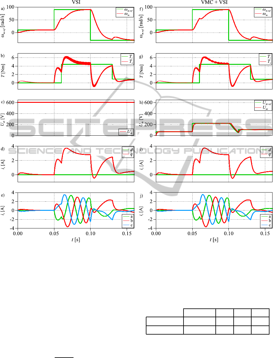
Figure 6: Simulation test results obtained for PMSM fed by: VSI - 1
st
column, VMC + VSI - 2
nd
column.
voltage demanded for PMSM operation under vari-
ous conditions (i.e. angular velocity and load torque).
Sinusoidal waveforms of PMSM phase currents are
presented in figure 6.e and 6.j respectively.
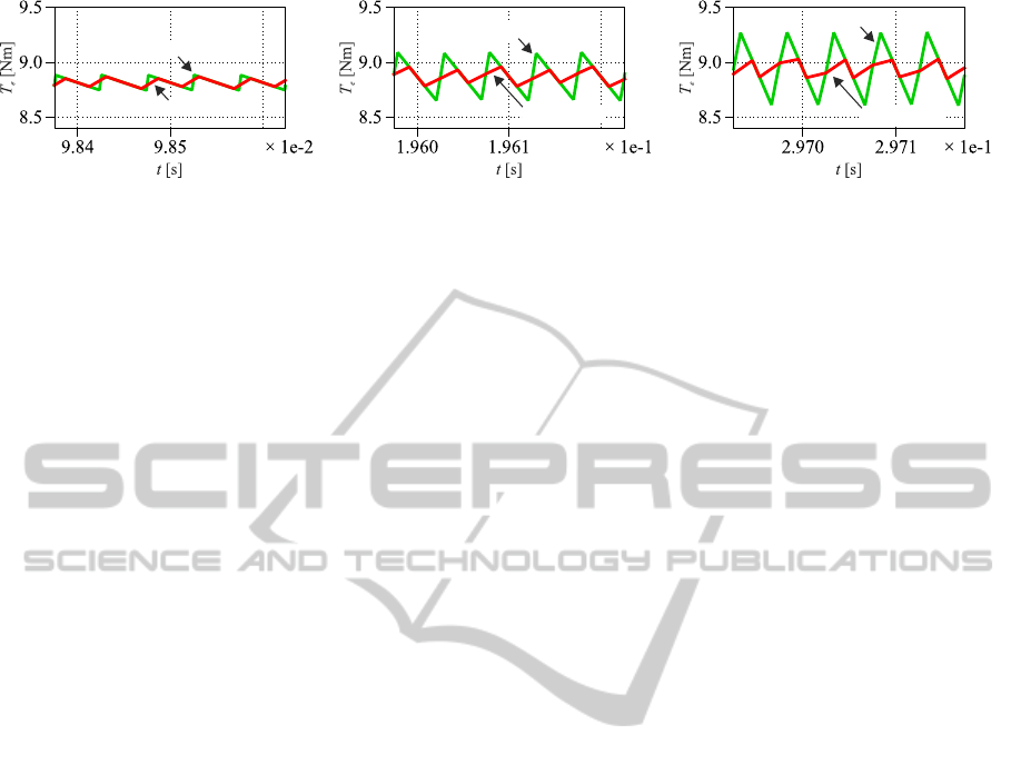
4.2 Torque Ripple Analysis
Proposed control system with VMC and NN state
feedback controller was examined in terms of PMSM
torque ripple minimization. In order to evaluate
the effectiveness of the proposed control system for
torque ripple minimization, the torque ripple factor
(TRF) was introduced (Qian et al., 2004):
TRF =
T
e pk−pk
T
eN
× 100% (11)
where: T
e pk−pk
- peak-to-peak torque ripple, T
eN
-
rated torque of the PMSM.
Enlarged parts of the PMSM’s electromagnetic
torque waveforms observed for control systems (i.e.
PMSM fed by VSI, PMSM fed by VMC + VSI) in
a steady-state are shown in figure 7. Corresponding
values of TRF are listed in table 3.
Table 3: Torque ripple factor.
ω
m
[rad/s] 10 50 100
VSI TRF [%] 1.57 4.95 7.57
VMC + VSI TRF [%] 1.21 2.06 2.04
From table 3 and figure 7 it can be seen that signifi-
cant torque ripple minimization is achieved when pro-
posed control system (i.e.VMC + VSI) is used.
ICINCO2014-11thInternationalConferenceonInformaticsinControl,AutomationandRobotics
368
VSI
VMC + VSI
VSI
VMC + VSI
VSI
VMC + VSI
a) b) c)
Figure 7: Electromagnetic torque waveforms of PMSM fed by VSI and VMC + VSI in a steady-state for the related load
torque: a) ω
m
= 10rad/s, b) ω
m
= 50rad/s, c) ω
m
= 100rad/s.
5 CONCLUSIONS
It was found that neural network state feedback
controller can be successfully used to control non-
stationary and non-linear plant (i.e. PMSM fed by
VSI with VMC) in terms of torque ripple minimiza-
tion. Use of the proposed controller causes, that lin-
earization and decoupling process of the plant are not
needed. It was also found that DC voltage of the VSI
can be precisely controlled with the help of an addi-
tional VMC control system.
Based on 2 low-order low-pass filters adaptive for-
mula used to obtain an appropriate inverter gain with
respect to actual value of the reference velocity was
introduced.
Simulation test results confirm similar dynamic
performance and significant torque ripple minimiza-
tion of designed control system in comparison to
PMSM fed by VSI with stationary state feedback con-
troller - torque ripple factor is at least 30% smaller.
Experimental verification of the described con-
trol system with neural network based adaptive state
feedback controller and voltage matching circuit is
planned in the future.
REFERENCES
Ferrari, S. and Stengel, R. F. (2005). Smooth function ap-
proximation using neural networks. IEEE Transac-
tions on Neural Networks, 16(1):24–38.
Grzesiak, L. M. and Tarczewski, T. (2011). Permanent mag-
net synchronous motor discrete linear quadratic speed
controller. In IEEE International Symposium on In-
dustrial Electronics, ISIE 2011, pp. 667–672. IEEE.
Grzesiak, L. M. and Tarczewski, T. (2013). PMSM servo-
drive control system with a state feedback and a
load torque feedforward compensation. COMPEL:
The International Journal for Computation and Math-
ematics in Electrical and Electronic Engineering,
32(1):364–382.
Gulez, K., Adam, A. A., and Pastaci, H. (2008). Torque
ripple and EMI noise minimization in PMSM using
active filter topology and field-oriented control. IEEE
Transactions on Industrial Electronics, 55(1):251–
257.
Hasanien, H. M. (2010). Torque ripple minimization of per-
manent magnet synchronous motor using digital ob-
server controller. Energy Conversion and Manage-
ment, 51(1):98–104.
Huang, S. and Tan, K. K. (2012). Intelligent friction model-
ing and compensation using neural network approxi-
mations. IEEE Transactions on Industrial Electronics,
59(8):3342–3349.
Hung, J. Y. and Ding, Z. (1993). Design of currents to re-
duce torque ripple in brushless permanent magnet mo-
tors. IEE Proceedings B Electric Power Applications,
140(4):260–266.
Jahns, T. M. and Soong, W. L. (1996). Pulsating torque min-
imization techniques for permanent magnet AC motor
drives - a review. IEEE Transactions on Industrial
Electronics, 43(2):321–330.
Kojima, M., Hirabayashi, K., Kawabata, Y., Ejiogu, E. C.,
and Kawabata, T. (2004). Novel vector control system
using deadbeat-controlled PWM inverter with output
LC filter. IEEE Transactions on Industry Applica-
tions, 40(1):162–169.
Krishnan, R. (2010). Permanent Magnet Synchronous and
Brushless DC Motor Drives. CRC Press, New York.
Petrovic, V., Ortega, R., Stankovic, A. M., and Tadmor, G.
(2000). Design and implementation of an adaptive
controller for torque ripple minimization in PM syn-
chronous motors. IEEE Transactions on Power Elec-
tronics, 15(5):871–880.
Qian, W., Panda, S. K., and Xu, J.-X. (2004). Torque ripple
minimization in PM synchronous motors using iter-
ative learning control. IEEE Transactions on Power
Electronics, 19(2):272–279.
Steinke, J. K. (1999). Use of an LC filter to achieve a motor-
friendly performance of the PWM voltage source in-
verter. IEEE Transactions on Energy Conversion,
14(3):649–654.
Tarczewski, T. and Grzesiak, L. M. (2013). PMSM fed
by 3-level NPC sinusoidal inverter with discrete state
feedback controller. In 15th European Conference on
Power Electronics and Applications, EPE 2013, pp.
1–9. IEEE.
Tarczewski, T., Niewiara, L., and Grzesiak, L. M. (2014).
Torque ripple minimization for PMSM using voltage
matching circuit and neural network based adaptive
state feedback control. In 16th European Conference
on Power Electronics and Applications, EPE 2014.
IEEE.
Tewari, A. (2002). Modern Control Design: with MATLAB
and SIMULINK. Wiley, Chichester.
ApplicationofArtificialNeuralNetworkStateFeedbackControllertoTorqueRippleMinimizationofPMSM
369
