
Design of a Multi-robot Bin Packing System in an Automatic
Warehouse
S. J. You and S. H. Ji
Korea Institute of Industrial Technology, Sa-3-dong, Sangrok-gu, Ansan-si, KyungKi-do, South Korea
Keywords: Automatic Warehouse, Bin Packing System, Multi-robots, Mobile-robot Motion Planning, Collision Model.
Abstract: It is possible to reconfigure supply chains with less cost and time if we use the mobile-robot bin packing
system. So, many companies attempt at adopting mobile robots as their new carrier in their own warehouse.
However, it is difficult to utilize indoor service robots as a carrier due to the localization problem, the safety
problem, and the narrow bin packing environment. So we propose a practically applicable solution
technique for a multi-robot bin packing system in an automatic warehouse, which assures a reasonable
safety, computation time and a real world application for more than 3 multi-robots. First, design criteria for
out bin packing system are introduced. Second, we suggest some sketch of robot mechanical parts. Finally,
the method of managing multi-robots in an automatic warehouse robot design with a collision motion
planner is proposed.
1 INTRODUCTION
Multi-agent motion planning is one of the interesting
and essential research fields in robotics. The demand
for various specialized robots has been increasing
rapidly with the advancement of robot technology.
For example, it is possible to reconfigure supply
chains with less cost and time if we use the mobile-
robot bin packing system. So, many companies
attempt at adopting mobile robots as their new
carrier in their own warehouse. However, it is
difficult to utilize indoor service robots as a carrier
due to the localization problem, the safety problem,
and the narrow bin packing environment. So we
propose a practically applicable solution technique
for a multi-robot bin packing system in an automatic
warehouse, which assures a reasonable safety,
computation time and a real world application for
more than 3 multi-robots. First, design criteria for
out bin packing system are introduced. Second, we
suggest some sketch of robot mechanical parts.
Finally, the method of managing multi-robots in an
automatic warehouse robot design with a collision
motion planner is proposed
Multi-agent motion planning is still a challenging
field of research, having some technical difficulties
in resolving conflict among agents. The centralized
approaches have been faced with problems such as
the curse of dimensionality, complexity,
computational difficulty, and NP-hard problem
(Canny, 1988); (Akella, 2002).
To overcome these problems in the approach, we
proposed the extended collision map method (Ji,
2007). We modified the collision map such that the
method enables N agents to proceed with the
collision-free operation according to the priority by
going on the collision avoidance process one after
another from the highest priority agent. Yet, in this
method, the mutual relation regarding the collision
region among agents was not analyzed.
In this regard, in this paper the mutual relation
regarding the collision region is analyzed, and based
upon the studied collision features, (M,D) network
model which can express the traveling features of
multi agent is shown. (M,D) network model can
express not only the collision features between two
agents but also the complicated mutual interference
among more than three agents. Likewise, the
collision-free operation of multi agent can be
designed and the operating finish time of agents can
be figured by using (M,D) network model.
The remainder of the paper is organized as
follows: Section 2 defines design criteria for our bin
packing system and some sketch of robot
mechanical parts. Section 3 presents the concept of
the key technique of this paper – Collision model.
Section 4 provides the way how to plan collision-
533
J. You S. and H. Ji S..
Design of a Multi-robot Bin Packing System in an Automatic Warehouse.
DOI: 10.5220/0005098505330538
In Proceedings of the 11th International Conference on Informatics in Control, Automation and Robotics (ICINCO-2014), pages 533-538
ISBN: 978-989-758-040-6
Copyright
c
2014 SCITEPRESS (Science and Technology Publications, Lda.)
free motion of multi-agents based on the (M,D)
network model. Finally, this paper is concluded in
Section 5.
2 BIN PACKING SYSTEM AND
MECHNICAL PARTS
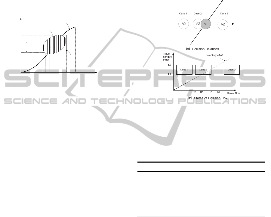
2.1 Warehouse
Our warehouse is shown as in Fig. 1. There are
multiple chutes, storing sites, and a charging station.
Multiple robots pick some items in the chutes
and move to storing sites and place the items on the
box with predefined address tag in the storing sites.
And when they have low batteries or have no job,
they move to the charging station.
We assume that the communication works at any
place and has sufficient network channels. And the
intelligent space can provide a central planner with
essential and necessary information for motion
planning and motion monitoring. This information
includes all the agents’ motion status and all the
static and moving obstacles’ positions (Lee, 2000);
(Norihiro, 2003).
Global off-line path planner (Central planner)
can give the safe paths to all agents. In this paper,
‘safe path’ is the meaning that no agent will not
crossover any other agent’s starting point or
destination if it keeping on its own safe path.
Therefore there can be intersection points among
agents’ paths.
Figure 1: Warehouse.
2.2 Bin Packing System
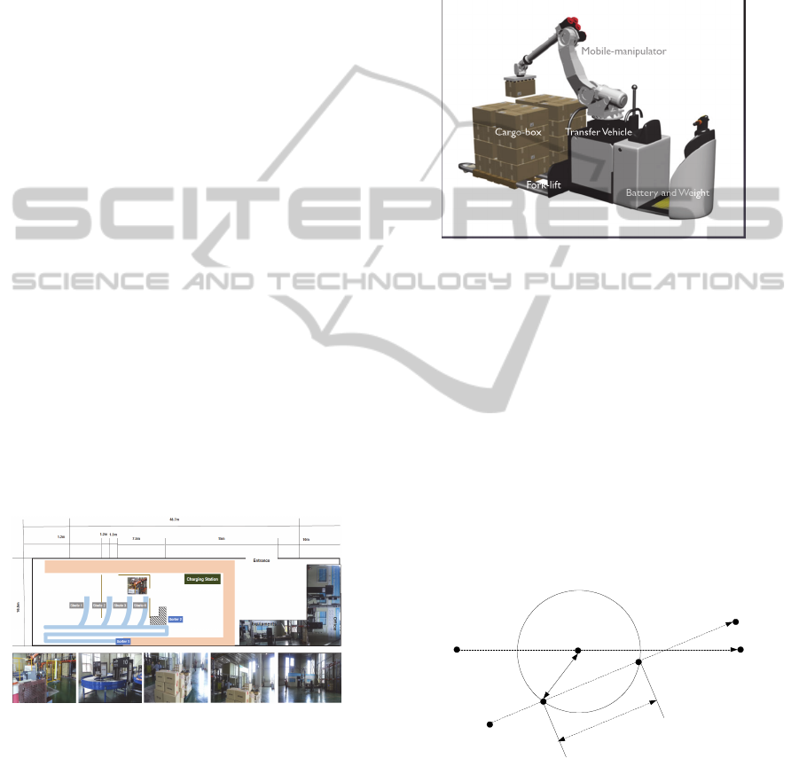
Our final prototype of bin packing robot is as shown
in the Fig. 2. The system is composed of a transfer
vehicle, a fork-lift, a manipulator, and battery and
weight balancer.
We design the system which can be reconfigured
easily. For example, the system has only a for-lift
and a transfer vehicle without a manipulator when
all the items are in the cargo box. Finally, we will
design four types of robots such as followed;
- First, the robot is a moving cargo.
- Second, the robot is a mobile-manipulator.
- Third, the robot is a moving cargo with a fork-lift.
- Fourth, the robot is a mobile manipulator with a
fork-lift.
Figure 2: Our expected final prototype.
2.3 Collision Map
The concept of the original collision map was
presented in the previous study (Lee, 1987). The
original concept is as follows: An agent with a
higher priority is called 'agent 1', and an agent with a
lower priority is called 'agent 2'. The radii of the two
agents are r
1
and r
2
respectively. Using the obstacle
space scheme, agent 1 can be represented as the
agent with a radius of r
1
+r
2
, and agent 2 can be
considered as a point agent. The original trajectory
of agent 1 is assumed not to be changed. On the
contrary, agent 2 must modify its trajectory if a
collision is anticipated.
Path of agent 2
Path of agent 1
C
o
l
l
i
s
i
o
n
l
e
n
g
t
h
(k)
1
)(k
f2
P
)(k
01
P
(k)
1
P
)(k
f1
P
(k)
2
21
r r
)(k
02
P
Figure 3: Paths of two agents and collision.
If the path of agent 2 meets agent 1 with radius
of r
1
+r
2
, the two agents will collide with each other.
At this instant, the part of agent 2's path that
overlaps with agent 1's path, is called the 'collision
length', which is denoted by the portion between
λ
1
(k) and λ
2
(k) in Fig. 3. These overlapped parts are
ICINCO2014-11thInternationalConferenceonInformaticsinControl,AutomationandRobotics
534
examined at every instant of the sampling time k to
construct a 'collision region.' If the TLVSTC
(traveled length versus servo time curve, simply
trajectory) of agent 2 arrives at the region, the two
agents will collide with each other under the original
trajectories. This colliding case is shown in Fig. 4. In
this figure, the vertical axis represents the traveled
length of agent 2 and the horizontal axis represents
the elapsed time.
Length
Time
Collision
region
Collision
length at
time k
TLVSTC
Collision
box
s
k
f
k
e
k
1
k
k
e
l
s
l
f
l
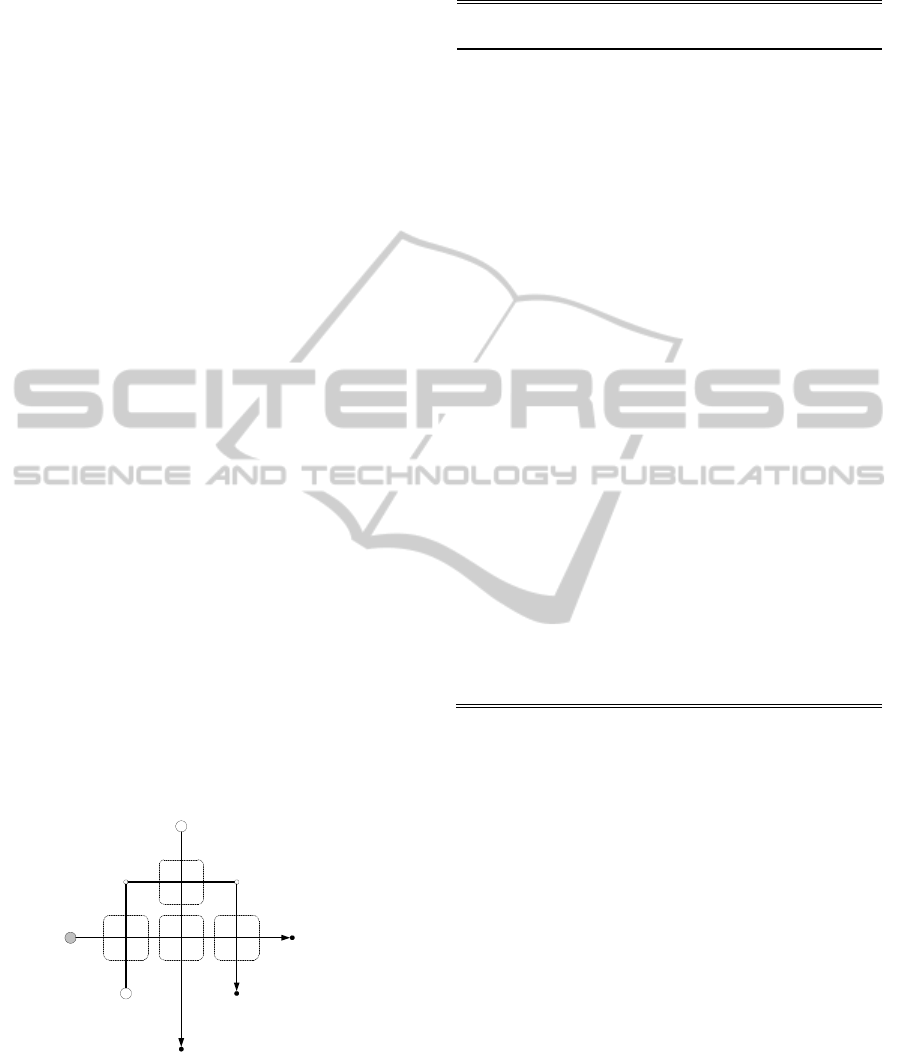
Figure 4: TLVSTC and collision region.
Because it is difficult to mathematically
represent the boundary line of the collision region,
the concept of ‘collision box’ was introduced. This
concept can be explained in Fig. 4. In this figure, k
s
is the time when agent 1 starts overlapping agent 2’s
path. Also k
e
is the time when agent 1 leaves agent
2’s path. l
s
and l
e
are the minimum and maximum
values of the collision length in the collision region,
respectively.
The extended collision map method considers
more than two agents which have many intersections
in workspace. Thus, the intersection and its
corresponding collision region should be described.
An intersection is denoted by the symbol
jiI
k
ij
;
(1)
,where i and j represent the identifying number of
the agent, and k is the ordering number denoting
intersections along the path of the agent i from the
starting point. The corresponding collision region of
the intersection is expressed as R
k
ij
.
3 COLLISION MODEL
3.1 Collision Characteristics
We assume A1 has an intersection point with A2
which is less important than A1 in Fig.5(a). The
possible position relations between two agents
around the intersection point are as followed; First,
A1 passes through the intersection region before A2
enters the region(Case1). Second, the agents collide
with each other(Case2). Third, A1 reach the region
only after A2 exits the region. The states of collision
box related the agents in Fig.3(a) as shown in
Fig.5(b), where L1 and L2 are the minimum
traveled length and maximum length from start
position to the intersection region along A2’s path
Figure 5: Collision-States of two agents.
Time characteristics related to collision region
including T
k
(k=1,2,3,4) in Fig. 3(b) are shown on
Table I, and we define two variables, ‘M’ and ‘D’, in
order to describe the collision states among agents.
Table 1: Characteristics related to collision region.
Variables Meaning
T
1
Time when A1 reaches the collision region
T
2
Time when A2 reaches the collision region
T
3
Time when A2 exits the collision region
T
4
Time when A1 exits the collision region
T
1d
A2’s delayed start time
T
2d
A2’s delayed start time
M T
3
-T
1
D T
4
-T
2
,
We can predict whether the agents collide with
each other by the variables, M and D, related to the
collision region and define the collision-free
navigation condition of an agent as followed:
[Collision-free Navigation Condition]. When an
agent has more than one intersection with other
agents which have higher priorities than the agent, it
should not have any collision region of which
collision characteristics are positive.
3.2 Impact of Time Delay on
Characteristics
When A2, the agent with lower priority, is delayed
DesignofaMulti-robotBinPackingSysteminanAutomaticWarehouse
535
in departure by T
2d
without change in path shape nor
velocity profile in order to avoid a collision with A1,
the time variables are changed as followed:
Because the agents keep up their own path shape
and A1 keeps up its velocity profile, neither T
1
nor
T
4
is affected by A2’s delayed departure. T
2
and T
4
which are related to the agents’ path shape and A2’s
TLVSTC are exchanged with T
2
+ T
2d
and T
3
+T
2d
,
because A2’s TLVSTC is shifted to the right by T
2d
in Fig. 3(b). Thus, impact of time delay on collision
characteristics is define as shown in Eq.(2).
M’ = M + T
2
d
(2)
D’ = D – T
2d
,where K
0
is a constant which is determined initially
by the agents’ paths shapes and velocity profiles.
According to Eq.(2) M increases and D decreases
when A2 is delayed in departure.
3.3 Collision Model
We present the collision model which express
collision relations and predict possibility of
collisions among the agents. And all of the agent’s
minimum delayed departure time for collision-free
navigation can be extracted from the model. The
elements of collision model are defined in Table 2.
Now, we express the collision model from the
case in Fig. 4 as the network model shown in Fig. 5.
There are three agents(agent 1, agent 2, and agent 3)
with path shapes as shown in Fig.4. We assume that
all of agent’s radii are 5m and there velocities are
1m/sec, 2m/sec, and 1m/sec. We assume also that it
takes no time for them to accelerate, decelerate, or
turn around. And we assume their priority order is
1-2-3.
agent 1
path of agent 1 : P1 - P4
path of agent 2 : P2 - P5
path of agent 3 : P3 - P6 - P7 - P8
I
31
1
A
1
A
3
A
2
agent 2
agent 3
P
1
(0,50)
P
3
(25,25)
P
4
(100,50)
P
2
(50,100)
P
5
(50,0)
P
7
(75,75)P
6
(25,75)
P
8
(75,25)
I
21
1
I
31
2
I
32
1
scale : ( m, m )
Figure 6: Three agents with intersection points.
The collision network model is as followed: V =
{1,2,3}, P=(1,2,3), E={(2,1,1), (3,1,1), (3,1,2),
(3,2,1)}. L and T are shown in Fig. 5.
Table 2: Elements of collision model.
Symbols Meaning
V
Node space(V) = { 1, …, N}.
This is a set of agent identified numbers.
E
Link space(E) = { (i, j, k) ∈ V
2
x N | i ∈
P
+
j
, k=1,…, k(i,j) }.
This is a set of collision regions among agents.
P
+
j
is explained in priority order space, and the
links go from the agent with higher priority to the
other agent.
k(i,j) is the number of collision regions between
agent j and agent i . So some agent can have more
than two links with other agent if they have several
collision regions
C
Link relation space(C) = { (M
ij
k
, D
ij
k
) ∈ R
2
|
(i,j,k) ∈ E }.
This is a set of collision characteristics, M and D in
the Table I.
T
Node navigation characteristic space(T) =
{ (T
i
delayed
, T
i
traveled
) ∈ R
2
}.
This is a set of agents’ delayed departure times and
pure traveled time from the start point to the
destination.
P
Priority order space(P) = {(N
1
, …, N
N
) ∈ V
N
| N
i
is the identified number of the agent with the i
th
highest priory}
This is a set of agent orders in which each agents
are placed from an agent with the highest priority
to an agent with the lowest priority.
P
+
j
is the set of agents which have higher priorities
than agent j in P and P
-
j
is the set of agents which
have lower priorities than agent j in P, the space of
priority order space
When an agent(A
i
) is delayed by T
i
d
, the collision
model is changed related the agent node. For inlet
links from the higher priority agents, M’s increase
and D’s decrease by delayed departure time(T
i
d
). In
the other, for outlet links to lower priority agents,
M’s decrease and D’s increase by the same amount.
4 COLLISION MODEL BASED
MULTI-AGENT MOTION
PLANNER
As a result of the time delay, the safe inlet link may
be dangerous. So in this paper we propose an
iterative approach to find the minimum delayed
departure time for collision avoidance as followed:
ICINCO2014-11thInternationalConferenceonInformaticsinControl,AutomationandRobotics
536
A1
A2 A3
M
21
1
, D
21
1
M
31
1
, D
31
1
M
31
2
, D
31
2
M
32
1
, D
32
1
{T
1
delayed
, T
1
travelded
}
{T
2
delayed
, T
2
travelded
}{T
3
delayed
, T
3
travelded
}
Figure 7: Collision model for three agents in Figure 4.
[Collision-Free Motion Planner for an Agent on
Collision Model]
Step1: we extract the links on which the agent is
expected to collide with higher priority agents (Inlet
Links) by use of collision characteristics.
Step2: we define an instantaneous delayed departure
time (T
i
d
) as the maximum of the Ds’ in the selected
links.
T
i
d
= max ( {D
ij
k
| j ∈ P+(i), (i, j, k)∈E
(3)
s.t. M
i
j
k
> 0 and D
i
j
k
> 0})
Step3: we modify node variables, link parameters
by T
i
d
.
Step4: if there is no inlet links to the agent which is
dangerous, the agent can go to its destination safely.
Otherwise, we execute above actions from the first
stage.
[Collision-free Motion Planner for Multi-agents
on Collision Model]
First, we select an agent from the priority order
space (P) by use of priority index.
Second, if the agent has the highest priority, go
to first stage. Otherwise, we apply the collision-free
motion planner on collision model to the agents so
that the agent can navigate safely.
Third, if the selected agent has the lowest
priority, the all of the agents can navigate safely, and
finish up this algorithm. Otherwise, increase priority
index by 1 and go to first stage.
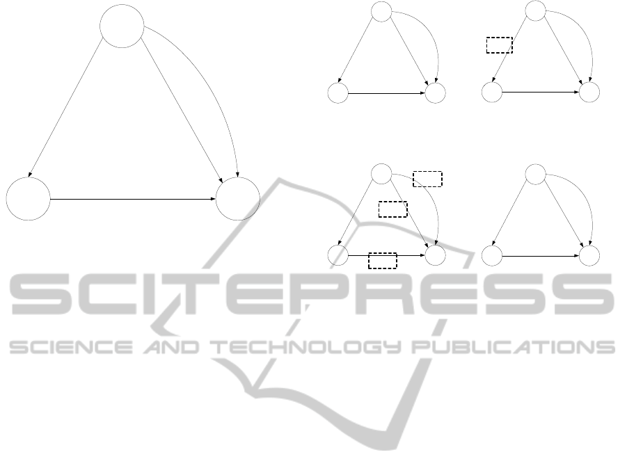
Te procedure of this algorithm for the three
agents in Fig. 6 is shown in Fig. 8. Because the all
agents’ links is in a safe state in Fig. 8(d), we can
predict that the agents can navigate without collision
among them.
A1
A2 A3
{40,0}
{30, 0}
{30, 0}
{35, -5}
{0, 100}
{20,100} {27.5, 75}
A1
A2 A3
{40,0}
{2.5, 27.5}
{2.5, 27.5}
{7.5, 22.5}
{0, 100}
{20,100} {0, 75}
A1
A2 A3
{20 , 20}
{2.5, 27.5}
{2.5, 27.5}
{27.5, 2.5}
{0, 100}
{0, 100} {0, 75}
A1
A2 A3
{20 , 20}
{2.5, 27.5}
{2.5, 27.5}
{27.5, 2.5}
{0, 100}
{0, 100} {0, 75}
(a)
(b)
(c)
(d)
Figure 8: Procedure of collision-free motion planner on
collision model for the agents in Figure 6.
5 CONCLUSION
In this paper, we proposed a practically applicable
solution technique for a multi-robot bin packing
system in an automatic warehouse, which assures a
reasonable safety, computation time and a real world
application for more than 3 multi-robots. For the
purpose, we suggested design criteria for out bin
packing system and some sketch of robot
mechanical parts. Finally, the method of managing
multi-robots in an automatic warehouse robot design
with a collision motion planner was proposed.
Because our method is fast and scalable,
complete, so our method can be used practically to
multi-AGVs in factories, airports, and big buildings
where there are sensor networks obtaining global
position information.
Because our method is fast and scalable,
complete, so our method can be used practically to
multi-AGVs in factories, airports, and big buildings
where there are sensor networks obtaining global
position information. And we have a plan which
consists of three steps as follows:
- First, Manual Picking & Palletizing +
Autonomous Navigation
- Second, Robotic Picking & Palletizing +
Multiple Autonomous Navigation
- Third, Robotic Picking & Palletizing + Multiple
Autonomous Navigation + Remote Operated
Controller
DesignofaMulti-robotBinPackingSysteminanAutomaticWarehouse
537

ACKNOWLEDGEMENTS
This work was supported by the Next-Generation
New Technology Development Programs
(Development of network-based collective
intelligence robot technologies coping with
unstructured environments) from the Ministry of
Science, ICT and Future Planning.
REFERENCES
Latombe, J. C. 1991. Robot Motion Planning, Kluwer
academic publishers.
Quottrup, M. M., Bak, T.; R. Izadi-Zamanabadi, 2004.
Multi-Robot Planning : A Timed Automata Approach,
Proc. of IEEE Int. Conf. on Robotics and Automation.
Canny, J. F. 1988. The Complexity of Robot Motion
Planning, MIT Press.
Azarm, K. and G.Schmit, 1997. Conflict-free Motion of
Multiple Mobile Robots Based on Decentralized
Motion Planning and Negotiation, Proc. of IEEE Int.
Conf. on Robotics and Automation.
Lee, B. H.; C. S. G. Lee, 1987. Collision-Free Motion
Planning of Two Robots, IEEE Transactions on
Systems, Main, and Cybernetics, vol.17, no1, pp. 21-31.
Barber, K. S.; T. H. Liu, and S.Ramaswamy, 2001.
Conflict Detection During Plan Integration for Multi-
Agent Systems, IEEE Transactions on Systems, Man,
and Cybernetics, vol. 31, no. 4, pp. 616-627.
Lee, J. H. and H. Hashimoto, 2000. Intelligent space,
Proc. of IEEE/RSJ Int. Conf. on Intelligent Robots and
Systems, vol. 2, pp. 1358-1363.
Ji, S. H., J .S. Choi, and B. H. Lee, 2007. A Computational
Interactive Approach to Multi-agent Motion Planning,
International Journal of Control, Automation, and
Systems, vol. 5, no. 3, pp. 295-306.
Akella S., and S. Hutchinson, 2002. Coordinating the
Motions of Multiple Robots with Specified
Trajectories, Proc. Of IEEE Int. Conf. on Robotics and
Automation.
Norihiro, H.; K. Kiyoshi, M.Kehji and S.Yasuyuki, 2003.
Collaborative Capturing of Experiences with
Ubiquitous Sensors and Communication Robots, Proc.
of IEEE Int. Conf. on Robotics & Automation, pp.
4166-4171.
ICINCO2014-11thInternationalConferenceonInformaticsinControl,AutomationandRobotics
538
