
Novel Hybrid Receiver for Interference Cancellation and Suppression
in Sidehaul System
Sangmi Moon, Hun Choe and Intae Hwang
Dept. of Electronics and Computer Engineering, Chonnam National University
300 Yongbongdong Bukgu Gwangju, 500-757, Republic of Korea
Keywords: Full Successive Cancellation (FSC), Hybrid Receiver, Irc, Sic, Sidehaul System, Suppression.
Abstract: Recently, the 3rd Generation Partnership Project (3GPP) has developed a sidehaul system to cope with the
explosively increasing mobile data traffic. Nevertheless, numerous challenging technical problems that need
to be overcome remain. One of the major problems is interference management between small cells. In this
paper, we propose a novel hybrid receiver for full successive cancellation (FSC) to reduce the interference
from neighboring cells in the sidehaul system. The proposed receiver can cancel and suppress interference
by integrating the interference rejection combining (IRC) technique with successive interference
cancellation (SIC). We perform a simulation based on the 20-MHz bandwidth of the 3GPP LTE-Advanced
technology. Simulation results show that the proposed receiver can achieve a lower error rate and a higher
throughput compared to conventional receivers.
1 INTRODUCTION
Explosive demands for mobile data communication
are driving changes in the way mobile operators
respond to the challenging requirements of higher
capacity and improved quality of user experience
(QoE). Currently, the 3rd Generation Partnership
Project (3GPP) has developed small cells by
increasing the node deployment density in
macrocells to handle increased capacity
requirements (http://www. qualcomm.com/media/
documents/files/1000x- more- smallcells- web-.pdf;
Hamalainen, 2012; Nakamura , 2012).
This approach, nevertheless, has a fundamental
problem in that the cost of operation and installation
increases with the number of small cells deployed.
Especially, the fixed small cell is inefficient in
environments where the maximum local traffic
changes by the hour owing to the increase in the
floating population.
To solve this problem, we need to develop a
moving small cell that can be connected to the
macro base station through a wireless backhaul
system, and is movable by the user. Nevertheless,
there is a limit to the network capacity that can be
increased only by wireless backhaul technologies.
As the network capacity is limited by the wireless
backhaul system that connects the macro base
station, a sidehaul system between moving small
cells is required to enable a moving small cell to
communicate.
In moving small-cell environments, inter-cell
interference increases. Studies have been carried out
to solve the interference problem by adopting a
transmission method to reduce the interference at the
base station, a cooperation technique between cells
(Samsung, 94-99; Sawahashi et al., 2010. ), and a
high-performance reception algorithm that handles
the interference at the receiver. In the former case,
each user equipment (UE) has to feed back the
channel information for the interference information
to be processed. In view of the possible inaccuracy
of the feedback information as well as the feedback
overhead due to the increase of the number of
antennas, there are restrictions on this interference
processing method that requires feedback.
Meanwhile, another interference processing method
at the receiver has recently attracted the attention in
3GPP as the method does not require feedback.
Network-assisted interference cancellation and
suppression (NAICS) is the technology used to
reduce the adverse effect of interference by using
interference cancellation receivers and interference
suppression receivers. In terms of improvement of
the capacity and interference cancellation, several
185
Moon S., Choe H. and Hwang I..
Novel Hybrid Receiver for Interference Cancellation and Suppression in Sidehaul System.
DOI: 10.5220/0005231801850191
In Proceedings of the 5th International Conference on Pervasive and Embedded Computing and Communication Systems (PECCS-2015), pages
185-191
ISBN: 978-989-758-084-0
Copyright
c
2015 SCITEPRESS (Science and Technology Publications, Lda.)
receiver algorithms based on the minimum mean-
square error (MMSE) have been proposed for multi-
cell environments. 3GPP Release 12 selects NAICS
as the study item (SI) and discusses the
improvement in performance, the type of support
information, and the overhead with network support
(3GPP TR 36.866 , 2014).
In this paper, we first describe the conventional
receiver used to reduce the inter-cell interference
and propose a hybrid receiver that integrates the
interference rejection combining (IRC) technique
with successive interference cancellation (SIC). The
paper is organized as follows. We present the
overview of the sidehaul system in Section 2.
Section 3 describes the conventional receivers. In
section 4, we propose the novel hybrid receiver for
achieving full successive cancellation (FSC).
Section 5 presents the performance analysis of the
proposed scheme through simulations. Finally, the
conclusion drawn is given in section 6.
2 OVERVIEW OF A SIDEHAUL
SYSTEM
2.1 Structure of Transmitter and
Receiver in a Sidehaul System
We design the structure of the transmitter and the
receiver used in the sidehaul system based on the
uplink of LTE-Advanced (3GPP, TS 36.211 , 2013).
Single carrier-frequency division multiple access
(SC-FDMA) has drawn great attention as an
attractive alternative to OFDMA, especially in the
uplink communications where a lower peak-to-
average power ratio (PAPR) greatly benefits the
mobile terminal in terms of transmit power
efficiency and reduced cost of the power amplifier.
Therefore, SC-FDMA has been adopted as the
access scheme in the sidehaul system.
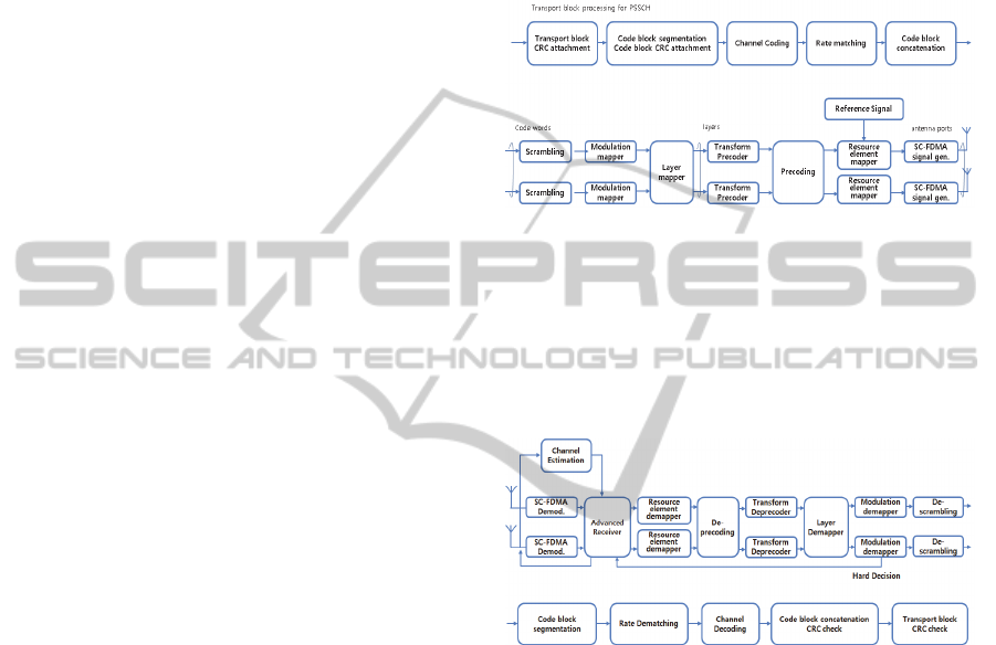
As depicted in Figure 1, the baseband signal
representing the physical sidehaul shared channel
(PSSCH) is defined in terms of the following steps:
- Channel Coding
- Scrambling
- Modulation of scrambled bits to generate
complex-valued symbols
- Mapping of complex-valued modulation
symbols onto one or several transmission
layers
- Transform precoding to generate complex-
valued symbols
- Precoding of complex-valued symbols
- Mapping of precoded complex-valued
symbols to resource elements
- Generation of complex-valued time-domain
SC-FDMA signal for each antenna port
After generating the PSSCH, the transmitter
sends SC-FDMA signal out through the wireless
channel.
Figure 1: Block diagram of transmitter in sidehaul system.
In the receiver, the received signal is usually
distorted by the channel characteristics. In order to
recover the transmitted signal, the channel is
estimated using a reference signal and compensated
in the receiver. Figure 2 shows the structure of the
receiver in the sidehaul system.
Figure 2: Block diagram of receiver in sidehaul system.
2.2 Structure of Resource Allocation in
a Sidehaul System
A physical resource block (PRB) is the minimal unit
used for resource allocation in a sidehaul system. A
PRB is defined as
consecutive SC-FDMA
symbols in the time domain and
consecutive
subcarriers in the frequency domain; the values of
the block parameters
and
are listed in
Table 1.
A PRB consists of
resource
elements (REs), corresponding to one slot in the
time domain and 180 kHz in the frequency domain.
Each radio frame is 10 ms long and consists of
20 slots of length 0.5 ms. A subframe is defined as
two consecutive slots; subframe i consists of slots 2i
and 2i+1.
In the sidehaul system, PSSCH is the channel
PECCS2015-5thInternationalConferenceonPervasiveandEmbeddedComputingandCommunicationSystems
186
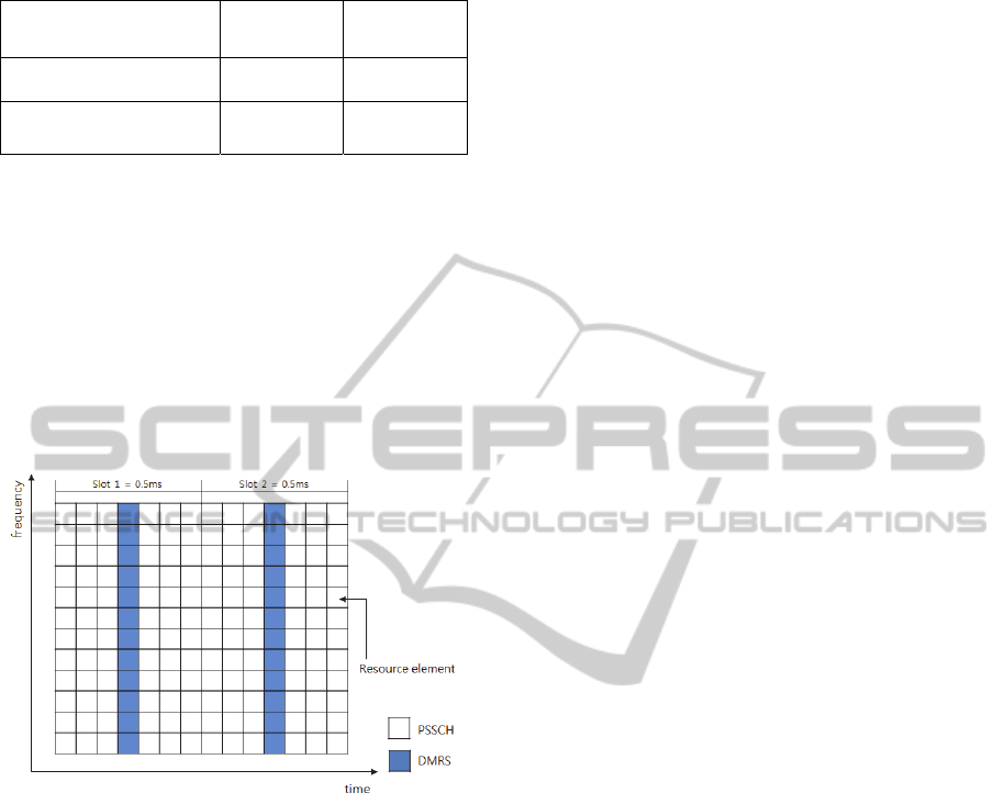
Table 1: Resource block parameters.
Configuration
Normal cyclic prefix 12 7
Extended cyclic
prefix
12 6
used for sidehaul data transmission, and the
demodulation reference signal (DMRS) is the
reference signal. DMRS for PSSCH in the frequency
domain will be mapped to the same set of PRB used
for the corresponding PSSCH transmission with the
same length expressed by the number of subcarriers,
whereas in the time domain, DMRS will occupy the
fourth SC-FDMA symbol in each slot with a normal
cyclic prefix (CP), as shown in Figure 3. In the case
of extended CP, DMRS will occupy the third SC-
FDMA symbol in each slot.
Figure 3: Mapping of demodulation reference signal
(DMRS).
3 CONVENTIONAL RECEIVER
In this section, we describe conventional receivers
based on techniques such as MMSE, IRC, SIC, and
maximum likelihood (ML). For a sidehaul system,
the received signal at an RE can be expressed as:
∑
, (1)
where and are the desired signal targeted to the
UE and its corresponding propagation channel
respectively, and
and
( 1,2,…, are
interfering signals and their corresponding channels;
is an additive white noise vector. It can be
assumed that the signals transmitted from different
sources and different MIMO layers are mutually
independent of each other and have unit power. Thus
we have
,
, and
, ,1…, . Note
that the actual transmission power and the precoding
matrix are factored in the channel matrix.
3.1 MMSE Receiver
The MMSE receiver treats interference as white
noise. Along with the channel matrix for the desired
signal, only interference-plus-noise power
needs to be estimated by the MMSE receiver. The
MMSE receiver can be expressed as
. (2)
3.2 IRC Receiver
The MMSE-IRC receiver is expected to outperform
the MMSE receiver in strong interference scenarios.
The MMSE-IRC receiver can be expressed as
. (3)
where
is the interference and noise covariance
matrix. As the DMRS sequence of the serving cell is
known at the receiver, the interference and noise
covariance matrix can be estimated as
,
,
, (4)
where , is expressed as
,
,
,
,
. (5)
Here, , is the DMRS sequence of the serving
cell.
3.3 SIC Receiver
There are two types of SIC receivers. In the first
type, only symbol demodulation is involved in the
SIC process; in the other, forward error correction
FEC decoding is involved. It can be expected that if
FEC decoding is involved in the SIC process, the
performance will be better compared to the receiver
that uses only symbol demodulation. It has to be
noted that FEC decoding requires detailed coding
information and resource allocation information of
the interference signal to be available to the UE
receiver. This requires considerable system
coordination and signaling overheads. In this study,
the SIC receiver that uses only symbol demodulation
is employed.
The flow chart of the SIC receiver is depicted in
Figure 4.
The SIC receiver can be expressed as
∑
, (6)
NovelHybridReceiverforInterferenceCancellationandSuppressioninSidehaulSystem
187
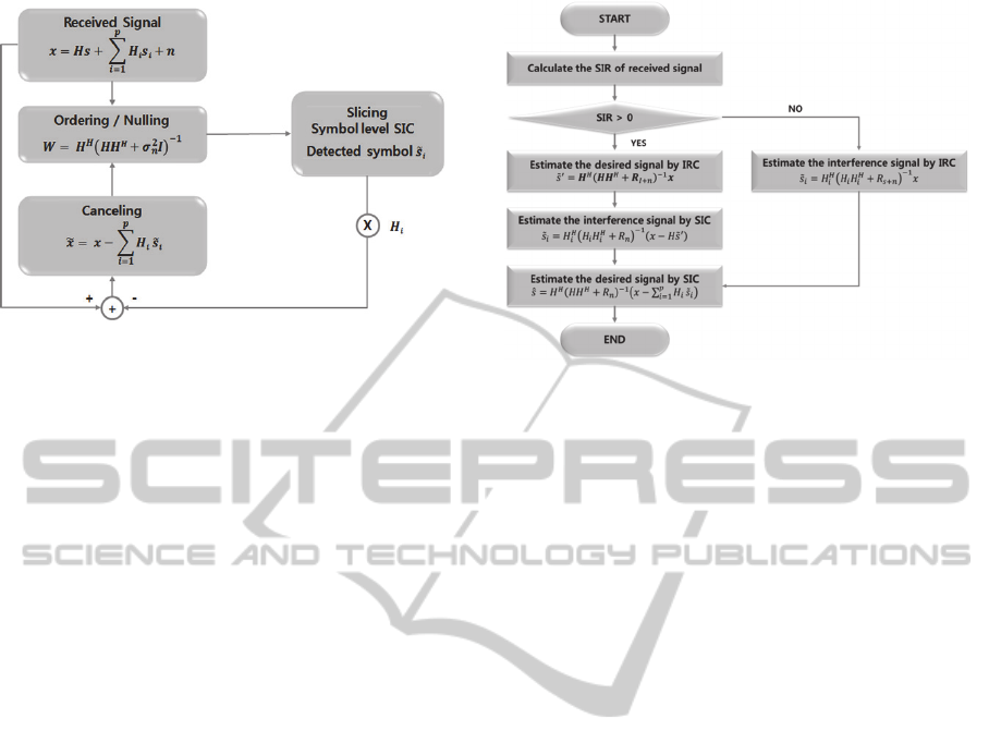
Figure 4: Flow chart of SIC receiver.
where
is the quantized estimation of the
interference signal
.
The receiver needs to know the modulation order
of the interference signal and the channel matrix of
the interferers as well. The SIC receiver requires
system assistance to receive the interference
modulation order information and means to estimate
the interference channel metrics.
3.4 ML Receiver
ML receivers provide an optimal performance
compared to other receiver structures. SIC receivers
can be viewed as sub-optimal realizations of ML
receivers. SIC receivers have less computational
complexity with some performance degradation
compared to ML receivers. The ML receiver, similar
to the SIC receiver, requires information of the
modulation order and channel metrics of
interference signals. The ML receiver can be
expressed as
,
,
,…,
arg
,
,
,…,
∈
∑
(7)
where is the set of constellation points of the
modulations used for the desired signal and the
interference signal. In the actual implementation of
an ML receiver, the estimate of the interference
signal
,
,…,
can be discarded.
4 PROPOSED RECEIVER
In this section, we propose the novel hybrid FSC
receiver that combines IRC with SIC. The flow chart
of the proposed FSC receiver is depicted in Figure 5.
According to the steps shown in Figure 5, the
signal-to-interference ratio (SIR) of the received
Figure 5: Flow chart of FSC receiver.
signal is calculated. If the interference signal is
greater than the desired signal, SIR < 0, and the
interference signal is estimated by IRC and the
estimated interference signal ̃
is expressed as
,
(8)
where
is the desired signal and noise
covariance matrix. Finally, the desired signal is
estimated by SIC and this estimated desired signal ̂
is expressed as
∑
,
(9)
where
is the noise covariance matrix.
If the desired signal is greater than the
interference signal, SIR > 0; in this case, the desired
signal can be estimated by the following steps.
First, the desired signal is estimated by IRC and
̃
is expressed as
̃
. (10)
The interference signal is then estimated by SIC,
and ̃
is expressed as
. (11)
In order to cancel the estimated interference in the
received signal, the desired signal is estimated by
SIC and the estimated desired signal ̂ is expressed
as (9).
5 SIMULATION RESULTS AND
PERFORMANCE ANALYSIS
In this section, we present the link level simulation
results to compare the performance of the receivers
mentioned in the previous sections. We consider one
PECCS2015-5thInternationalConferenceonPervasiveandEmbeddedComputingandCommunicationSystems
188
neighbor cell causing the inter-cell interference in
the serving cell. Table 2 shows the general
simulation parameters and defines the simulated
environment. Table 3 shows the power-delay profile
(PDP) of an extended typical urban (ETU) channel.
The simulation parameters are based on the 20-MHz
bandwidth of 3GPP LTE-Advanced technology. The
time-variant frequency-selective channel is modeled
as an ETU channel with a maximum Doppler
frequency (
of 300 Hz (R4-131291, 2013). In the
case of the desired signal, we use the MCS
index, and the channel coding parameters are
listed in Table 3.
Otherwise, the channel coding is
not considered in the interference signal because of
system complexity. The signal-to-noise ratio (SNR)
range is 16 dB–40 dB and SIR is 24 dB.
Table 2: Resource block parameters.
Parameter Value
Carrier frequency 2 GHz
Bandwidth 20 MHz
Sample frequency 30.72 MHz
Subframe duration 1 ms
Subcarrier spacing 15 kHz
FFT size 2048
Occupied subcarriers 1200
No. of
subcarriers/PRB
12
Cyclic Prefix (CP) Normal CP
No. of OFDM
symbols/subframe
14 (Normal CP)
Channel Model ETU, fd = 300Hz
MIMO Configuration 4 × 4
Channel Estimation Ideal
Receiver
Conventional Receivers:
MMSE, IRC, SIC,
and ML
Proposed Receiver: FSC
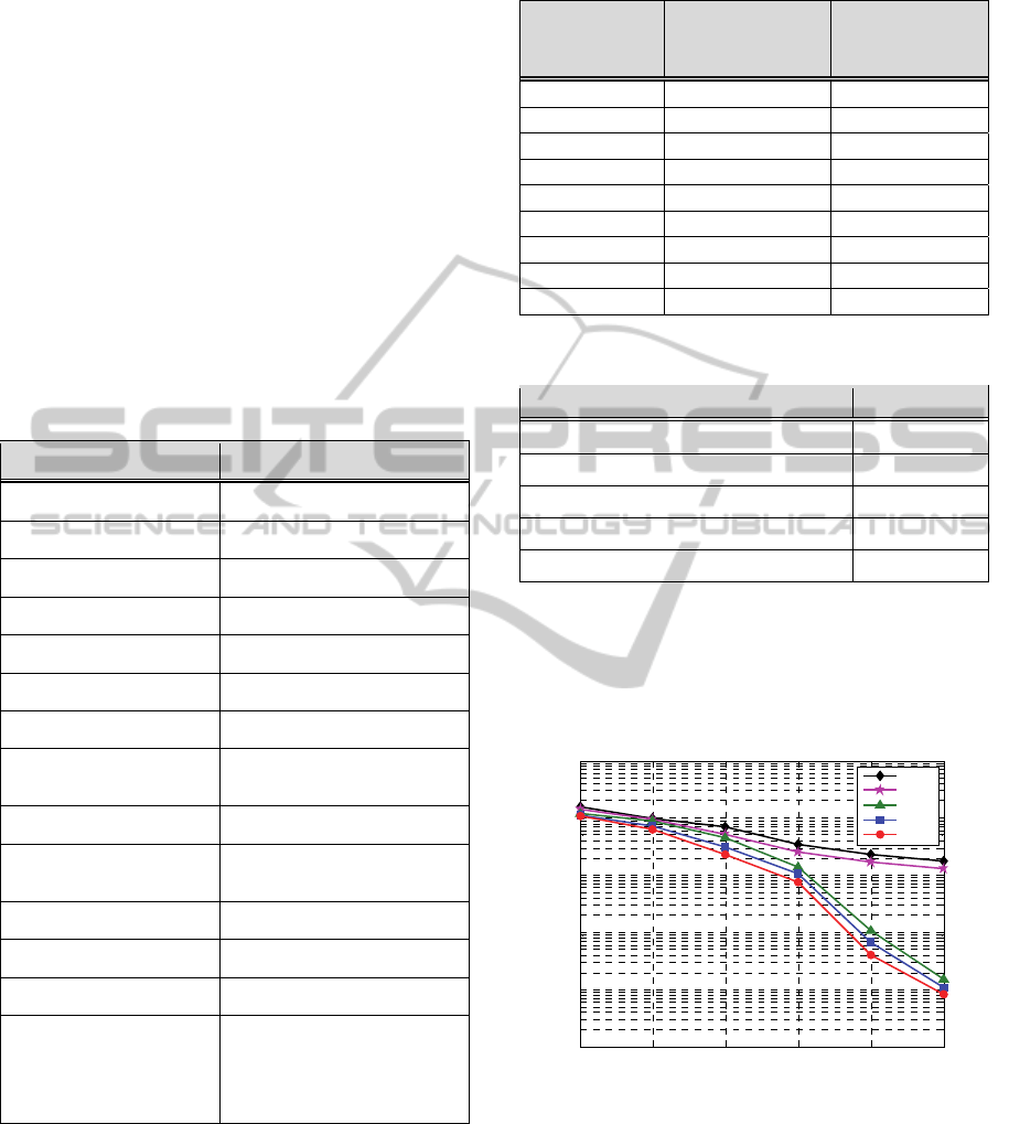
Figure 6 shows the coded bit-error rate (BER) for
the different types of receivers. As referenced to a
coded BER of 10
, the minimum required SNR for
each type of receiver is given in Table 5. We
observe degradation in the MMSE and IRC receivers
because of strong interference. On the other hand,
the SIC, FSC and ML receivers outperform the
MMSE receiver by cancelling the interference
Table 3: ETU Channel Model.
Excess tap
delay [ns]
Excess tap
delay [sample]
Relative
power
[dB]
0 0 -1.0
50 2 -1.0
120 4 -1.0
200 6 0.0
230 7 0.0
500 15 0.0
1600 49 -3.0
2300 71 -5.0
5000 154 -7.0
Table 4: Channel Coding Parameter: MCS Index 27.
MCS Index 27
CQI Index 14
Modulation 64QAM
Target code rate 0.8525 (5/6)
Information bit payload 637776
Binary channel bits per subframe 75600
signal, and the BER of receivers improves in the
following order: SIC, FSC, and ML. The SNR of the
proposed FSC receiver required to achieve the coded
BER of 10
differs by about 1 dB compared with
that of the ML receiver having ideal performance.
Figure 6: BER performance of different receiver types.
Figure 7 shows the block error rate (BLER) for the
different types of receivers compared. As referenced
to a BLER of 10
, the minimum required SNR for
each type of receiver is given in Table 6. Compared
with the coded BER, the overall error rate is higher.
It can be seen that the BLER performance of the
receivers is similar to the coded BER performance.
15 20 25 30 35 40
10
-5
10
-4
10
-3
10
-2
10
-1
10
0
SNR [dB]
Coded BER
MMSE
IRC
SIC
FSC
ML
NovelHybridReceiverforInterferenceCancellationandSuppressioninSidehaulSystem
189
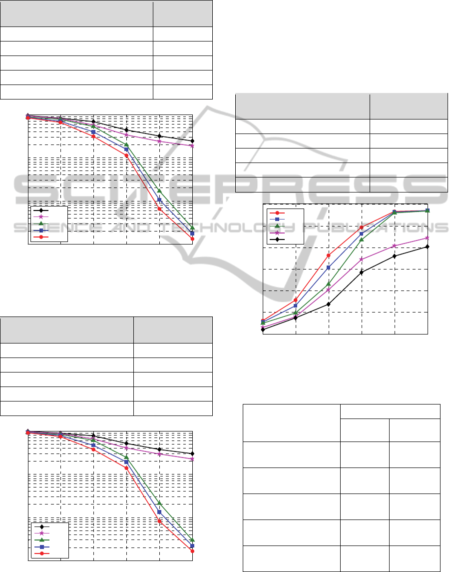
Table 5: SNR requirement according to receiver type
(Coded BER).
Performance Evaluation
(Coded BER < 1%)
SNR
MMSE 42 dB
IRC 41 dB
SIC 31 dB
FSC 30 dB
ML 29 dB
Figure 7: BLER performance of different receiver types.
Table 6: SNR requirement according to receiver type
(BLER).
Performance Evaluation
(BLER < 10%)
SNR
MMSE More than 40 dB
IRC More than 40 dB
SIC 31.5 dB
FSC 30.8 dB
ML 30 dB
Figure 8: FER performance of different receiver types.
Figure 8 shows the frame error rate (FER) for the
different types of receivers. As referenced to an FER
of 10
, the minimum required SNR for the
different receivers studied is given in Table 7. It can
be seen that achieving the required FER
performance requires an SNR that is 1–2 dB higher
than that for achieving the BLER performance.
Table 7: SNR requirement according to receiver type
(FER).
Performance Evaluation
(FER < 10%)
SNR
MMSE More than 40 dB
IRC More than 40 dB
SIC 32 dB
FSC 31.2 dB
ML 30.5 dB
Figure 9: Throughput performance of different receiver
types.
Table 8: Throughput according to receiver type.
Max. Data Rate
Throughput [Mbps] =
285 Mpbs (theory)
SNR
30 dB 40 dB
MMSE
141.37
Mbps
201.34
Mbps
IRC
171.07
Mbps
211.17
Mbps
SIC
216.86
Mbps
284.15
Mbps
FSC
230.78
Mbps
284.38
Mbps
ML
245.71
Mbps
284.53
Mbps
Figure 9 shows the throughput of the different
receivers, and the throughput at SNRs of 30 and 40
15 20 25 30 35 40
10
-3
10
-2
10
-1
10
0
SNR [dB]
BLER
MMSE
IRC
SIC
FSC
ML
15 20 25 30 35 40
10
-3
10
-2
10
-1
10
0
SNR [dB]
FER
MMSE
IRC
SIC
FSC
ML
15 20 25 30 35 40
0
50
100
150
200
250
300
SNR [dB]
Throughput [Mbps]
ML
FSC
SIC
IRC
MMSE
PECCS2015-5thInternationalConferenceonPervasiveandEmbeddedComputingandCommunicationSystems
190

dB is given in Table 8. When applying the MCS
index 27, the theoretical maximum data rate, 285
Mbps, is calculated by considering the reference
signal and the control channel. The average
throughput of receivers improves in the following
order: MMSE, IRC, SIC, FSC, and ML.
6 CONCLUSION
In this paper, we propose the novel hybrid receiver
FSC to reduce the interference from neighbor cells
in a sidehaul system between moving small cells that
is used to improve data rate and capacity. The FSC
receiver combining the IRC with SIC satisfactorily
suppresses and cancels the interference. Simulation
results show that the proposed receiver has a lower
error rate and a higher throughput compared to
conventional receivers. In our future work, the
design of the frame structure would be considered to
improve the maximum data rate of the sidehaul
system.
ACKNOWLEDGEMENTS
This research was supported by Basic Science
Research Program through the National Research
Foundation of Korea(NRF) funded by the Ministry
of Education(NRF-2013R1A1A2007779).
REFERENCES
Qualcomm, “1000x: More Small Cells – Taking HetNets
to the Next Level,” (http://www.
qualcomm.com/media/documents/files/1000x-more-
smallcells-web-.pdf).
J. Hamalainen (Ericsson), 2012.2. “Towards
Heterogeneous Networks” (http://bnrg.cs.berkeley.edu
/~randy/Courses/CS294.S13/13.3.pdf).
T. Nakamura (NTT Docomo), 2012. “Further LTE
Enhancements toward Future Radio Access”.
Samsung, "Standard trends and performance analysis of
cooperative communication on a point-to-point
transmission based on LTE-A," TTA Journal, 139, 94–
99.
Sawahashi, M., et al. 2010. Coordinated multipoint
transmission/reception techniques for LTEadvanced,
IEEE Communications Magazine, 48(6), 26–34.
3GPP TR 36.866, March 2014. “Study on Network-
Assisted Interference Cancellation and Suppression
(NAICS) for LTE,” V12.0.1.
3GPP, TS 36.211, , Sept. 2013. “Evolved Universal
Terrestrial Radio Access (E-UTRA); Physical
channels and modulation,” V11.4.0.
R4-131291, Apr., 2013. “Discussion on Reference IC/IS
Receivers for NAICS”, Chicago, IL, US, 15-19.
3GPP TS 36.101, , March 2013 .“Evolved Universal
Terrestrial Radio Access (E-UTRA); User Equipment
(UE) radio transmission and reception,” V11.4.0.
NovelHybridReceiverforInterferenceCancellationandSuppressioninSidehaulSystem
191
