
Specific Electrodynamic Features of a Plasma Channel Created in
Gas by Powerful Femtosecond UV Laser Pulse
Application to the Problem of Guiding and Amplification of Microwave Radiation
A. V. Bogatskaya
1,2,3
, A. M. Popov
1,2,3
and E. A. Volkova
2
1
Department of Physics, Moscow State University, Moscow, 119991, Russia
2
D. V. Skobeltsyn Institute of Nuclear Physics, Moscow State University, Moscow, 119991, Russia
3
P. N. Lebedev Physical Institute, RAS, Moscow, 119991, Russia
Keywords: Laser and Microwave Radiation, Plasma Waveguide, Amplification of the Electromagnetic Radiation,
Electron Energy Distribution Function, Boltzmann Equation, Wave Equation in Paraxial Approximation.
Abstract: The evolution of strongly non-equilibrium plasma in a channel created in xenon by powerful KrF -
femtosecond laser pulse is studied. It is demonstrated that such a plasma channel can be used as a
waveguide for both transportation and amplification of the microwave radiation. The specific features of
such a plasma waveguide are studied on the basis of the self-consistent solution of the kinetic Boltzmann
equation for the electron energy distribution function in different spatial points of the gas media and the
wave equation in paraxial approximation for the microwave radiation guided and amplified in the channel.
The amplification factor in dependence on plasma channel radius, intensity and frequency of the input RF
radiation is analyzed.
1 INTRODUCTION
Recent technological progress in photonics and
materials science make it possible to obtain different
type of sources of radiation in terahertz (THz) or
subterahertz frequency range. Such sources of
radiation are of significant interest in a number of
research fields, such as chemistry (Skinner, 2010),
molecular biology (Meister, et al, 2013), medicine
(Titova, et al., 2013) and materials science (Grady,
et al., 2013). The continuously increasing interest for
terahertz and subterahertz radiation and its possible
applications is caused by its ability to penetrate
through a lot of materials (Jepsen, et al., 2011),
which are usually opaque in the infrared and visible.
Also, a number of physical and chemical processes
(vibrational dynamics of macromolecules and
crystalline lattices, reconstruction of hydrogen
bounds, etc.) can be controlled and governed by this
low frequency radiation.
The goal of our paper is to study the process of
transportation of focused microwave pulses in
subterahertz frequency band with low divergence
and possibility of their amplification in a plasma
channel at distances of order of 100 cm.
It is known, that if the electron energy distribution
function (EEDF) in a plasma is characterized by the
energy intervals with the inverse population, such
situation can be used for amplification of the
electromagnetic radiation (Bekefi, et al, 1961;
Bunkin, et al, 1973). Such EEDF can be easily
obtained in the process of multiphoton ionization of
a gas by a high-intensity laser pulse under the
conditions when the pulse duration is comparable or
even less than the average time interval between the
electron - atomic collisions. To realize the regime of
amplification one needs the gas of atoms or
molecules characterized by the transport cross
section increment with the energy where the peak of
photoelectrons is found to exist. Bogatskaya and
Popov (2013) had demonstrated that such a regime
of amplification of electromagnetic radiation can be
obtained in a xenon plasma created by powerful
(10
10
- 10
12
W/cm
2
) excimer KrF laser pulse
(
5=
Ω
eV) of femtosecond duration in
subterahertz frequency band (
tr
νω
< ,
tr
ν
is the
transport frequency) at time duration up to 100 ns. In
(Bogatskaya, et al, 2013) the possibility to amplify
the subtrerahertz radiation in different gases was
analyzed. The amplification regime in the air plasma
was studied in (Bogatskaya, et al, 2014a). It was
found that amplification in air plasma created by the
149
Bogatskaya A., Popov A. and Volkova E..
Specific Electrodynamical Features of a Plasma Channel Created in Gas by Powerful Femtosecond UV Laser Pulse - Application to the Problem of
Guiding and Amplification of Microwave Radiation.
DOI: 10.5220/0005252801490156
In Proceedings of the 3rd International Conference on Photonics, Optics and Laser Technology (PHOTOPTICS-2015), pages 149-156
ISBN: 978-989-758-093-2
Copyright
c
2015 SCITEPRESS (Science and Technology Publications, Lda.)

third harmonic of the Ti:Sa laser is also possible, but
positive value of a gain factor is found to exist only
for rather short durations ~ 20 ps. Hence there is a
possibility to amplify only extremely short radio-
frequency pulses of 2-3 cycles duration.
Bogatskaya, et al (2014b) demonstrated also
anomalous refractive properties of the strongly-
nonequilibrium plasma produced by the short UV
laser pulse. Such a plasma channel in the case of
low-frequency radiation (
tr
νω
< ) will be optically
more dense in comparison with unionized gas, in
contrast to the typical situation when plasma is an
optically less dense medium. Just such a situation is
of interest in respect to creation of a sliding-mode
plasma waveguide (Zvorykin, et al., 2010). In the
present paper we develop the self-consistent
approach to the problem of transportation of the
radio-frequency (RF) pulse in the non-equilibrium
plasma channel. This approach is based on joint
solution of the Boltzmann equation for the EEDF
evolution in the strongly non-equilibrium plasma
and the wave equation in the paraxial approximation
for the transported through the channel RF pulse.
The process of guiding and simultaneous
amplification of the RF radiation in the plasma
channel formed by a powerful KrF laser
femtosecond pulse in xenon is studied in dependence
of plasma channel radius and different parameters of
the input RF pulse.
2 ELECTRODYNAMIC FEATU-
RES OF A NONEQUILIBRIUM
PLASMA CHANNEL
For the radiation with frequency
ω
electrodynamic
features of a plasma channel are determined by
complex permittivity
'''
ωωω
ξξξ
i+= or complex
conductivity
'''
ωωω
σσσ
i+= which are related with
each other by the expression
.
4
1
ω
πσ
ξ
ω
ω
i+=
(1)
The general expression for the complex conductivity
in a relatively weak electromagnetic field when the
two-term expansion for the EEDF
),( tn
ε
is valid
can be written in a form (Ginzburg and Gurevich,
1960; Raizer, 1977):
.
),(
)(
))((
6
0
22
23
2
∞
∂
∂
−
+
+
=
ε
ε
ε
ενω
ωενε
π
ω
σ
ω
d
tn
i
tr
tr
p
(2)
Here
mne
ep
22
4
πω
= is the plasma frequency
squared,
e
n is the electron density and
mN
trtr
εεσεν
2)()( = is the transport frequency
of electron-atomic collisions,
)(
εσ
tr
is the transport
cross section and
N
is the gas density. We should
also mention that the evolution of the EEDF is rather
slow in time and external electromagnetic field of
frequency
ω
can be considered as the
quasimonochromatic one. The EEDF in eq. (2) is
normalized according to the condition
1),( =
εεε
dtn
.
If the transport frequency does not depend on energy
the complex refractive index is the same for an any
EEDF and for the case of weakly ionized plasma
(
ω
ν
ω
,
trp
<<
) can be written in the well-known
form
.
)(2)(2
1
'''
22
2
22
2
ωνω
νω
νω
ω
ωωω
tr
trp
tr
p
i
ninn
+
+
+
−
=+=
(3)
In particular, one derives from (3) that plasma is
optically less dense medium in comparison with the
unionized gas. Imaginary part of (3) determines the
absorption coefficient of the electromagnetic
radiation with frequency
ω
in plasma (Raizer,
1977):
)(
''''2
22
2
tr
trp
c
c
n
c
νω
νω
ξ
ωω
μ
ωωω
+
=×=×=
(4)
For an arbitrary dependence
)(
εν
tr
the definite
expression for the EEDF is of importance. In this
case more general expressions for refractive index
should be used:
∞
∞
∂
∂
−
+
==
∂
∂
−
+
−=−=
0
22
23
2
0
22
23
2
.
3
'2
''
,
3
1
''2
1'
ε
ε
νω
νε
ω
ω
ω
πσ
ε
ε
νω
ε
ω
ω
πσ
ω
ω
ω
ω
d
n
n
d
n
n
tr
tr
p
tr
p
(5)
Typically the EEDF decreases with the increase of
energy, i.e.
ε
∂∂n is negative and both of integrals
in (5) are positive. Hence, for such a more general
case plasma channel also appears to be optically less
dense in comparison with unionized media and the
absorption coefficient is positive,
0>
ω
μ
.
However, as the energy intervals with positive
derivative
ε
∂∂n contribute negatively to the
PHOTOPTICS2015-InternationalConferenceonPhotonics,OpticsandLaserTechnology
150
integrals (5), both of them may become negative.
Hence, plasma turns out to be an amplifying
medium. Also it can be optically more dense than
the neutral gas. The conditions, when integrals in (5)
can become negative are discussed in detail by
Bogatskaya, et al., (2014b). In particular, in the
energy range of inverse population in continuum for
low frequencies (
tr
νω
<< ) the condition
0)( <
εσε
ε
tr
d
d
(6)
should be satisfied to obtain the positive gain factor
in a plasma, i.e. transport cross section should grow
up rapidly than the linear dependence. If the
condition
0
41
<
tr
d
d
σε
ε
(7)
is fulfilled plasma will be optically more dense
medium as compared with the neutral gas. The latter
condition is much softer than the previous one and is
fulfilled for a lot of atoms and molecules. If both of
inequalities (6) and (7) are satisfied a plasma
channel can be used as the waveguide for both
transportation and amplification of the microwave
radiation. For the xenon plasma at an atmospheric
pressure such a guiding regime with amplification
can be realized up to subterahertz frequency band.
To study temporal evolution of real and
imaginary parts of plasma conductivity or
permittivity in plasma channel the Boltzmann
kinetic equation for the EEDF in two-term
expansion was solved numerically taking influence
of the transported RF field and electron – electron
collisions into account. The details of the numerical
procedure as well as the information on the set of
cross sections used can be found in (Bogatskaya, et
al., 2013).
For the case of multiphoton ionization of xenon
by KrF laser radiation inelastic processes do not
contribute to the evolution of the EEDF as the
excitation potentials exceed the value of 8.31 eV
while the position of the lowest photoionization peak
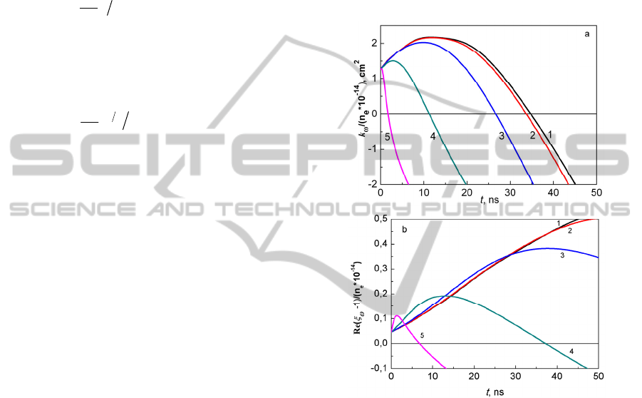
is approximately 2.87 eV. At Fig.1 we present the
calculations of temporal evolution of the gain factor
per one electron and the real part of plasma
permittivity for the RF frequency
11
105 ×=
ω
s
-1
and for different electronic densities. First, we note
that for rather low electronic densities both values
are found to increase in time while photoelectron
peak gradually shifts in time due to elastic collisions
towards lower energies but still locates in the range
where inequalities (6) and (7) are satisfied. Also it
can be seen that for rather small time intervals the
gain factor is proportional to the electronic density.
As about the real part of plasma permittivity
1Re −
ω
ξ
, for small time intervals this value
increases even faster than electronic density (see
Fig.1b). On the other hand, the increment of the
electron density leads to faster maxwellization of the
EEDF which results in the rapid decrement of the
time interval during which the gain factor is still
positive and the real part of plasma permittivity is
greater than unity.
Figure 1: The gain factor (a) and the real part of plasma
permittivity (b) per one electron in xenon plasma for
different electronic concentrations (cm-3): 1 - 1010, 2 -
1011, 3 - 1012, 4 - 1013, 5 - 1014. Negative values
correspond to absorption of a RF radiation in plasma.
Results of calculations of the gain factor for
different values of radiation intensity with a
frequency
11
105 ×=
ω
s
-1
are presented at Fig. 2 and
demonstrate that the time interval during which the
gain factor is positive reduces from 20 to 2 ns with
increase of RF intensity from zero to 10
3
W/cm
2
. For
the RF field intensity of 10 kW/cm
2
amplification in
a plasma channel is possible for very short times
about ~ 0.1 ns. From practical point of view it means
that microwave pulses of 2 ns duration can be
amplified up to the intensity of ~ 1 kW/cm
2
. We also
note that the amplification of RF pulse in the plasma
channel results in a decrement of electron energy,
i.e. an external electric field of a RF pulse leads to
the cooling of the plasma electron component.
SpecificElectrodynamicalFeaturesofaPlasmaChannelCreatedinGasbyPowerfulFemtosecondUVLaserPulse-
ApplicationtotheProblemofGuidingandAmplificationofMicrowaveRadiation
151
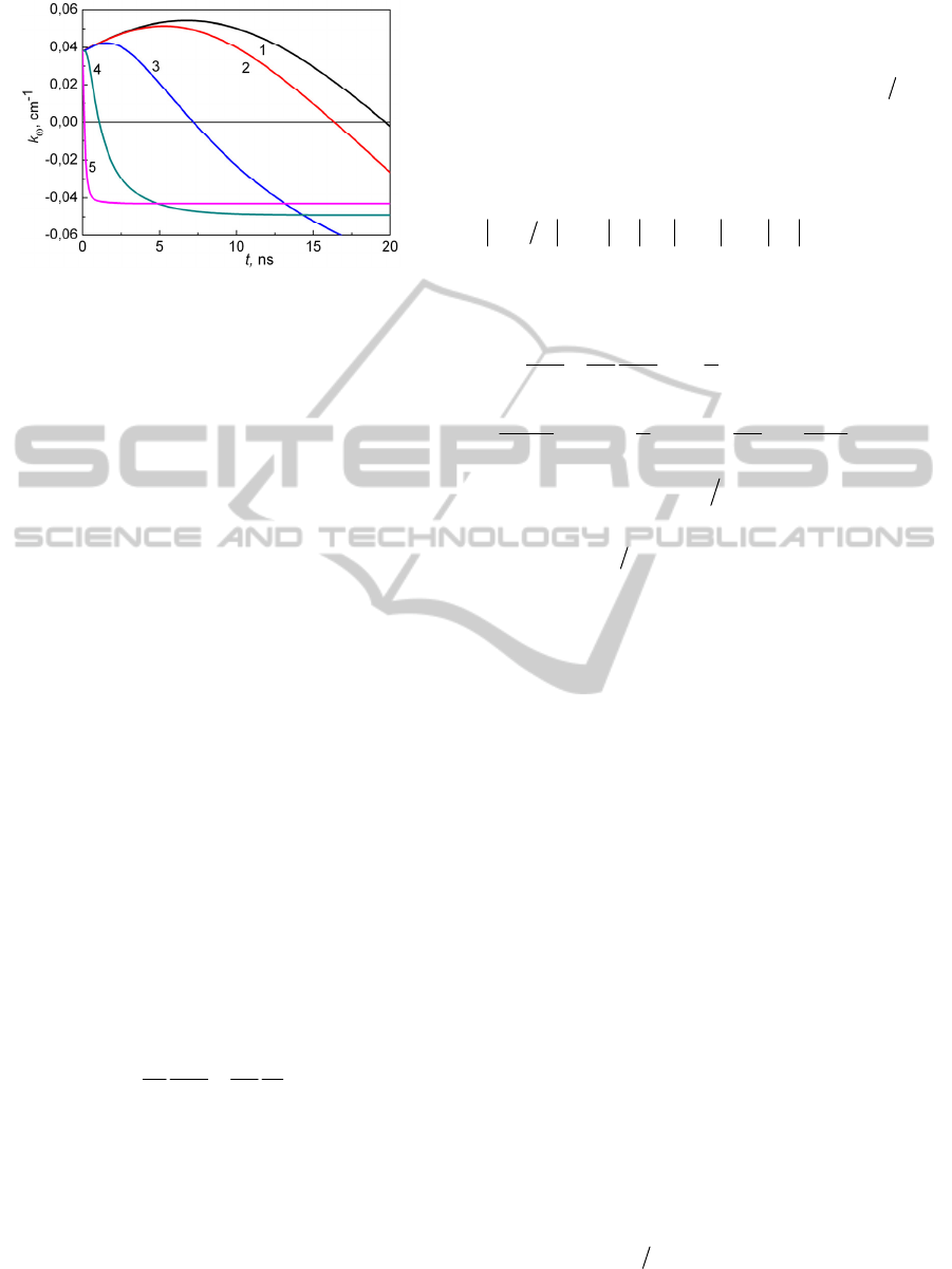
Figure 2: Time dependence of the gain factor of
electromagnetic radiation for different intensities of the
RF radiation (W/cm
2
): I=0 (1), 10 (2), 10
2
(3), 10
3
(4), 10
4
(5). The data obtained for electronic density
12
103 ×=
e
n
cm
-3
and
11
105 ×=
ω
s
-1
.
3 PROPAGATION AND AMPLI-
FICATION OF THE RF PULSES
IN A PLASMA WAVEGUIDE
In this chapter we will discuss propagation of a short
RF pulse in a plasma channel created in xenon by a
femtosecond KrF laser pulse. Our analysis is based
on the self-consistent solution of the wave equation
for the RF pulse and the Boltzmann equation for the
EEDF in a plasma channel in different spatial points.
If the RF field is weak enough and do not influence
on plasma parameters the set of Boltzmann
equations can be solved independently from the
wave equation. In this case the RF pulse propagates
in a channel with given plasma properties slow
varying in time. Much more complicated is the
situation when the RF pulse is strong enough and
produces significant effect on evolution of the
EEDF. In this case the self-consistent analysis of the
equations is mandatory.
As it is known, propagation of the electromagnetic
radiation in the medium is described by the wave
equation:
.
41
22
2
2
2
t
j
c
t
E
c
E
∂
∂
=
∂
∂
−∇
π
(8)
Here
E
is an electric field strength and
j
is a
density of electric current in a plasma. Further we
will suppose the field to be linearly polarized. To
analyze the process of microwave pulse propagation
qualitatively we use paraxial approximation for the
solution of eq. (8) (for details see the monograph of
Akhmanov and Nikitin (1997)). According to this
approximation for the pulse propagation along
z-
direction electric field
E should be represented as,
()()
.exp),,(),(
0
tkzitzEtrE
ωρ
−⋅=
(9)
Here
0
E is the envelope of the RF pulse, ck
ω
= is
the wave number and
ρ
is the perpendicular spatial
coordinate. If we neglect temporal dispersion, the
expression for the current density can be written in a
simple form
),(),( trEtrj
ω
σ
= . Assuming that
ωω
σωσ
<<∂∂ t
,
ωω
σσ
k<<∇
, i.e. plasma
conductivity is a slow-varying function in time and
space, one derives from (8) the following equation
for RF pulse envelope in the paraxial approximation
∂
∂
++
+∇−=
∂
∂
+
∂
∂
⊥
t
E
c
EkkiEk
E
t
E
c
n
z
E
ik
ω
ω
ω
ω
σ
π
ω
πσ
0
2
00
2
''
0
2
00
2
2
1
2
2
1
(10)
where
ck
'
4
ωωω
πσμ
=−=
is the plasma gain
factor (if
0<
ω
k plasma absorbs the radiation), and
ωπσ
ωω
21 in += is the complex refractive index.
The first term in the right part in Eq. (10) stands for
the diffraction divergence of the electromagnetic
field, the second one describes plasma focusing
(defocusing) features and the third term represents
the absorption (amplification) process. The last term
in the right part of (10) is small in comparison with
previous ones and gives some corrections to the
focusing/defocusing and amplification/absorption of
the wave field.
The case of our study is the situation when
0>
ω
k and
0
''
<
ω
σ
. Such a situation is of interest
with respect to creation of the plasma waveguide
being capable to amplify the transported radiation.
Actually, the amplification duration
ampl
τ
corresponds to the amplification distance of about
ampl
с
τ
×
(
ampl
τ
is the time interval of the positive
gain factor existence) which equals to tens of
centimetres. The same is for focusing properties of
the plasma, but the guiding length is typically
several times longer. So, a laser pulse creates the
plasma channel characterized by an amplifying and a
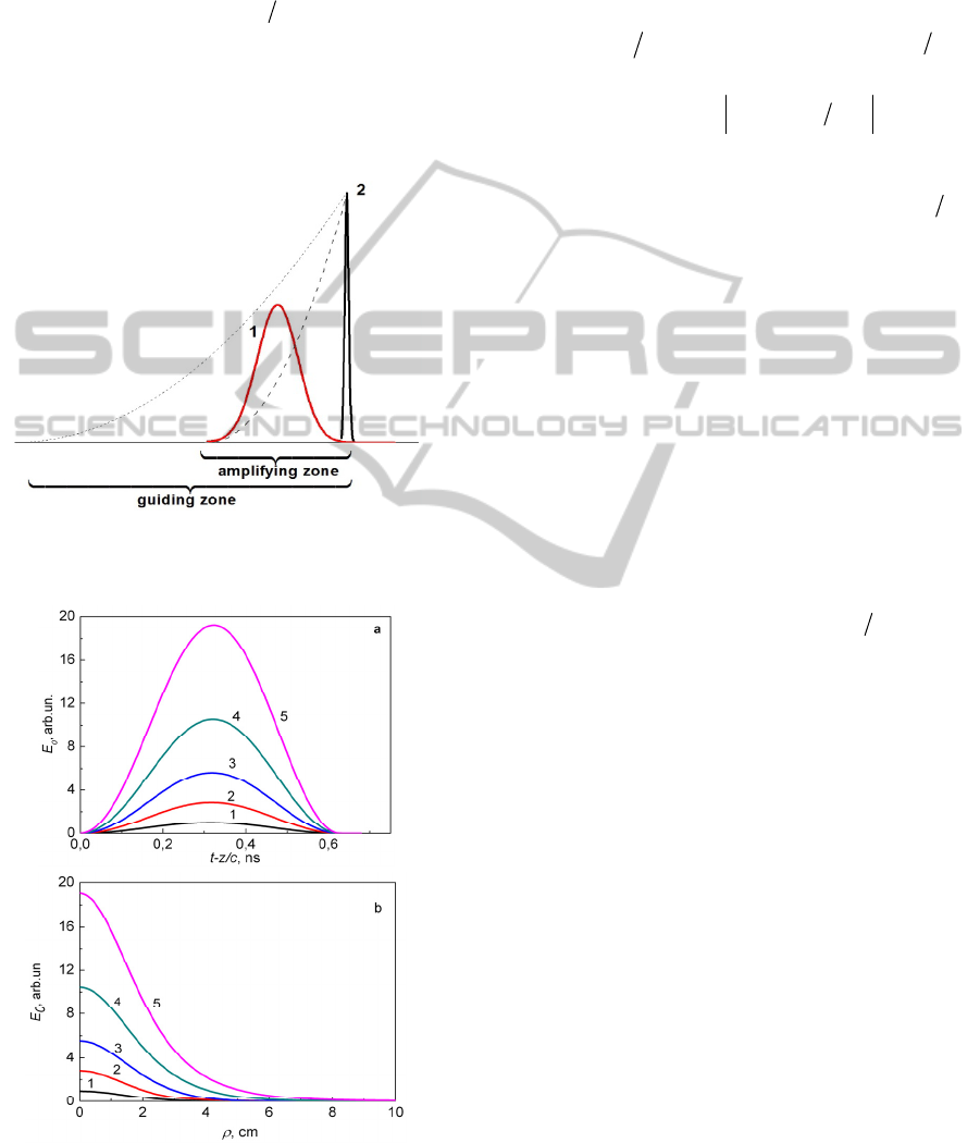
guiding «trails» (see Fig. 3). If we launch a laser
pulse and a RF pulse just one after another
simultaneously, the last one will continually locate
in the amplifying and guiding zones of a laser pulse.
It can be seen from Eq. (10) that in the case
1''21Re >−=
ωπσ
ωω
n the plasma channel can
partly suppress the diffraction divergence of the RF
radiation. If the condition
PHOTOPTICS2015-InternationalConferenceonPhotonics,OpticsandLaserTechnology
152
1)1(Re
22
>− Rkn
ω
(11)
(here
R
is the plasma channel radius) is satisfied
the channel will look like the waveguide and can
transport the radiation without divergence. For
11
105⋅=
ω
s
-1
and 7.16≈= ck
ω
cm
-1
and
001.0~1Re −=
ωω
Δ
nn (see Fig. 1b) the guiding
regime of propagation will be realized for
2>R
cm. It means a laser pulse in order to create such a
plasma channel with electron density
12
10~
e
n
cm
-3
should have the power at least in sub-Terawatt level.
Figure 3: Spatial structure of radio (1) and laser (2) pulses
for a given instant of time. Dash curves are spatial profiles
of the gain factor and the refractive index.
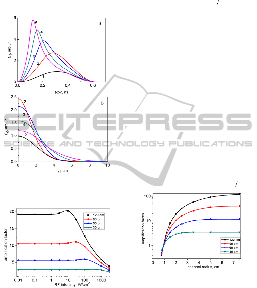
Figure 4: Temporal (1) and radial (2) profiles of the
electric field envelope of the amplifying pulse at different
propagation distances z: 1 – 0 cm, 2 – 30 cm, 3 – 60 cm, 4
– 90 cm, 5 – 120 cm. Initial peak intensity is 0.1 W/cm
2
.
First, we discuss the results of numerical integration
of the wave equation (10) for the case of weak field
when the contribution of the amplified RF pulse to
the EEDF evolution in the plasma channel can be
neglected. We assume that the RF pulse is
characterized by the sine-squared temporal envelope
)(sin~)(
2
0 p
ttE
τπ
, where
T
p
50=
τ
)2(
ωπ
=T
is the pulse duration. Typical distributions of the
electric field envelope
),,(
0
τρ
cztE −
for the
initial RF field and electron density distribution in
plasma channel Gaussian profiles, characterized by
the radius
2
0
=
ρ
cm versus the variable czt −=
τ
(for
0=
ρ
) and the radial variable
ρ
(for
2/
p
τ
τ
=
that corresponds to the maximum of the envelope of
the initial pulse) are presented at Fig. 4. The first of
these distributions can be considered as the temporal
envelope of the pulse at different fixed values of z or
as a distribution over z - coordinate at a fixed instant
of time. For the RF pulse duration
T
p
50=
τ
the
spatial length of the pulse is equal to
9.1≈
p
c
τ
cm.
For such a pulse
04.0≈
ω
k см
-1
and can be
considered to be nearly constant during the all
propagation time (see Fig. 2). The electric field
0
E
increases with propagation length approximately
exponentially
)exp(~
0
hzE with 024.0≈h cm
-1
.
This value is even little larger than
019.02 ≈
ω
k
cm
-1
, this difference arises from the partial focusing
effect during the propagation of the RF pulse in the
plasma waveguide. As about the radial distribution
(see Fig. 4b) it is nearly Gaussian one for all instants
of time.
The case of the initial RF pulse with relatively
high intensity when the guiding RF field contributes
significantly to the evolution of the EEDF in the
plasma channel is more interesting. The results of
such calculations for the initial RF intensity
3
0
10=I
W/cm
2
are presented at Fig. 5. It can be
seen for the same propagation length 120 cm there is
an increase in the peak intensity of the RF pulse just
only approximately six times. The pulse shape is
found to be distorted significantly, mainly because
of the dominant enhancement at the leading edge of
the pulse. As about the trailing edge of the pulse it
can be seen at fig.6a that for the propagation
distances of 60 cm and more the significant
absorption of the RF intensity is observed due to
dramatic reconstruction of the EEDF by the RF
pulse. As a result, the shorter RF pulse with leading
SpecificElectrodynamicalFeaturesofaPlasmaChannelCreatedinGasbyPowerfulFemtosecondUVLaserPulse-
ApplicationtotheProblemofGuidingandAmplificationofMicrowaveRadiation
153
peak and broader spectrum is formed in such a
propagation regime.
Figure 5. Temporal (1) and radial (2) profiles of the
electric field envelope of the amplifying pulse at different
propagation distances z: 1 – 0 cm, 2 – 30 cm, 3 – 60 cm, 4
– 90 cm, 5 – 120 cm. Initial peak intensity is 10
3
W/cm
2
.
Figure 6: Field amplification factor in dependence of the
input RF intensity for different propagation lengths (30,
60, 90 and 120 cm). Electronic density is
12
103×=
e
n
cm
-
3
and
5.0=
ω
THz, channel radius is 2 cm.
Let us now discuss the results of simulation
obtained for different initial parameters of an input
RF pulse (its peak intensity and frequency) and the
radius of the plasma channel. The dependence of the
field amplification factor
)0()(
00
== zEzEg for
different propagation lengths in dependence on peak
input RF intensity is presented at Fig. 6. In low
intensity limit the amplification factor do not depend
on the input intensity and reaches the value
20≈g
for the propagation length
120=L
cm. It means that
output intensity increases ~400 times in comparison
with the input one. In the range of input intensities
above 100 W/cm
2
the g-factor drops dramatically.
This results due to the rapid relaxation of the EEDF
in the presence of RF field and decrement of the
gain factor in the plasma channel. We also note the
local maximum which is well pronounced at the
input intensity 10 W/cm
2
for the L=120 cm. This
maximum appears to exist due to the additional
focusing effect of a plasma arising in the process of
EEDF relaxation at moderate intensities.
The dependence of the field amplification factor
on radius of a plasma channel is presented at Fig. 7.
The most important is the fact that in agreement with
(11) effective amplification of the RF pulse takes
place only for plasma channels of radius
2≥R
cm.
For
1<R
cm both effects of amplification and
plasma focusing cannot compensate the diffraction
divergence of the pulse and its intensity decreases
along the propagation length. The increment of the
channel radius above 2-4 cm leads to the saturation
of amplification factor at a level
)2exp( Lkg
ω
= .
Figure 7: Field amplification factor in dependence of the
plasma channel radius for different propagation lengths
(30, 60, 90 and 120 cm). Electronic density is
12
103 ×=
e
n
cm
-3
,
5.0=
ω
THz and input RF intensity is
0.01 W/cm
2
.
It should be mentioned that there is an existence
of the optimal value of frequency for effective RF
pulse amplification for a given channel radius (see
data at Fig. 8). For R=2 cm this frequency is rather
close to
11
105 ×=
ω
s
-1
. The decrement of the
frequency and, hence, increment of the microwave
PHOTOPTICS2015-InternationalConferenceonPhotonics,OpticsandLaserTechnology
154
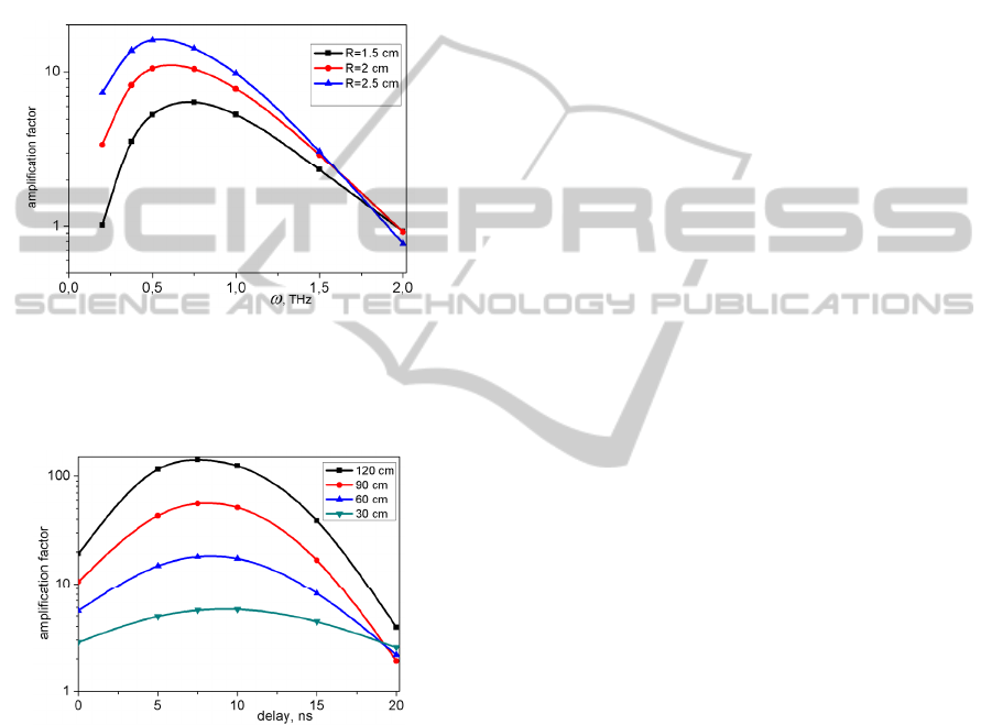
radiation wavelength leads to the violation of the
inequality (11) determining realization of the
guiding regime. On the other hand, the amplification
factor also falls down for high frequencies. When
the condition
tr
νω
≥ is fulfilled the gain factor
becomes negative and amplification regime is
impossible for any radius of the plasma channel. In
the situation under study the regime of amplification
can be realized for microwave frequencies
8.1≤
ω
THz.
Figure 8: Field amplification factor in dependence of RF
pulse frequency for different channel radius R. Electronic
density is
12
103 ×=
e
n
cm
-3
, input RF intensity is 0.01
W/cm
2
and propagation length is L=90 cm.
Figure 9: Field amplification factor in dependence of the
time delay between laser and RF pulses for different
propagation lengths (30, 60, 90 and 120 cm). Electronic
density is
12
103 ×=
e
n
cm
-3
, input RF intensity is 0.01
W/cm
2
and R=2 cm.
All discussed above data were obtained for the
zero delay between optical and RF pulses. On the
other hand, the data presented at Fig. 1 lead to the
conclusion that in order to increase the amplification
factor we should introduce the time delay between
laser and microwave pulses. The value of this delay
depends on the electronic density in the channel and
for
12
103 ×=
e
n
cm
-3
this delay should be of order of
10 ns. The data presented at Fig. 9 confirm the
above conclusion. The optimal delay in our situation
is ~7.5 ns. Due to increment of the gain factor and
refractive index during the initial period of the
EEDF evolution (see Fig. 1) such a delay value
allows to increase the amplification factor
approximately five times.
4 CONCLUSIONS
Thus, in this paper it is shown that the
nonequilibrium plasma channel created in xenon by
powerful femtosecond KrF laser can be used to
guide and amplify the RF pulses till subterahertz
frequency band. There is an opportunity to reach
significant amplification by the launching of the
laser and RF pulses, so that the RF pulse is
continually located in the guiding and amplification
zones of the laser pulse. Optimal parameters of
radio-frequency pulse for guiding and amplification
are discussed.
ACKNOWLEDGEMENTS
This work was supported by the Russian Foundation
for Basic Research (projects no. 14-02-31114, 15-
02-00373), by the noncommercial “Dynasty”
Foundation (program for support of students) and
the Educational Complex of the P.N.Lebedev
Physical Institute within the framework of the
Program of the Presidium of the Russian Academy
of Sciences for Young Researchers. Numerical
modeling was performed on the SKIF-MSU
Chebyshev supercomputer.
REFERENCES
Akhmanov, S. A. and Nikitin, S. Yu., 1997. Physical
Optics, Oxford.
Bekefi G., Hirshfield Y.L. and Brown S.C., 1961. Phys.
Fluids, 4, 173.
Bogatskaya, A. V. and Popov, A. M., 2013. JETP Lett.,
97, 388.
Bogatskaya, A. V., Volkova, E. A. and Popov, A. M.,
2013. Quantum Electronics, 43, 1110.
Bogatskaya, A. V., Volkova, E. A. and Popov, A. M., (a)
2014. In Proceedings of 2nd International Conference
on Photonics, Optics and Laser Technology, Lisbon,
Portugal, p. 199-204.
Bogatskaya, A. V., Smetanin, I. V., Popov, A. M., (b)
2014. J. Russian Laser Res., 35, 205.
Bunkin, F. V., Kazakov, A. A. and Fedorov, M. V., 1973.
Sov. Phys. Usp., 15, 416.
SpecificElectrodynamicalFeaturesofaPlasmaChannelCreatedinGasbyPowerfulFemtosecondUVLaserPulse-
ApplicationtotheProblemofGuidingandAmplificationofMicrowaveRadiation
155

Ginzburg, V. L. and Gurevich, A. V., 1960. Sov. Phys.
Usp. 3, 115.
Grady, N. K., et al., 2013. Science, 340, 1304.
Jepsen, P. U., Cooke, D. G. and Koch, M., 2011. Laser
Photonics Rev., 5, 124.
Meister, R., et al., 2013. PNAS, 110, 1617.
Raizer, Yu. P., 1977. Laser - Induced Discharge
Phenomena, Consultants Bureau, New York.
Skinner, J. L., 2010. Science, 328, 985.
Titova, V. T., et al., 2013. Scientific Reports, 3.
Zvorykin, V. D., Levchenko, A. O., Smetanin, I. V., and
Ustinovski, N. N., 2010. JETP Lett., 91, 226.
PHOTOPTICS2015-InternationalConferenceonPhotonics,OpticsandLaserTechnology
156
