
Inertial Measurement Units in Gait Analysis Applications
Questions, Suggestions and Answers
Harald Loose
1
, Katja Orlowski
1
and Robert Amann
2
1
Fachhochschule Brandenburg, Magdeburger Str. 50, 14770 Brandenburg, Germany
2
Fachhochschule Vorarlberg, Hochschulstr.1, Dornbirn, Austria
Keywords: IMU, Sensors, Systems, Gait Analysis, Gait Events, Gait Feature, Positions, Angles.
Abstract: The paper deals with inertial measurement units (IMU) and their application in gait analysis in the wide
range from movement monitoring through rehabilitation feedback to sports improvement. An IMU sensor
incorporates three microelectromechanical sensors - triple-axis gyroscope, accelerometer, magnetometer –
and, optionally, a barometer. The outputs of all sensors are processed by an on-board microprocessor and
sent over a serial interface using wired or wireless communication channels. The on-board processing may
include sensor conditioning, compensations, strap-down integration as well as determination of orientation.
The sensor output is sent to applications working on standard PC, tablets or smart phones using different
sampling rates. The output data of one IMU sensor allow motion analysis of the sensor unit itself as well as
the motion of the limb where the sensor is mounted to. Using a combination of two or more sensors the
movement of limbs/legs can be compared; their relative motion can be investigated; angles can be
calculated.
In general, in motion and gait analysis, we like to get primary information about the position of all
interesting points, the orientation of the limbs and the joint angles at each moment of time as well as derived
averaged and summarized characteristics about the motion and the gait. Based on our own investigations the
paper discusses how much information is really necessary to determine gait events and gait features for
different purposes.
1 INTRODUCTION
Inertial measurement units (IMU) are freely
available at the market: from low cost boards or
sticks to relatively expensive sensors assembled in
small and light weight packages. An IMU sensor
incorporates three microelectromechanical sensors -
triple-axis gyroscope, accelerometer, magnetometer
– and, optionally, a barometer. The outputs of all
sensors are processed by an on-board
microprocessor and sent over a serial interface using
wired or wireless communication channels. The on-
board processing includes sensor conditioning,
compensations, strap down integration (SDI) as well
as determination of orientation. Otherwise post-
processing tools are provided to perform these
calculations, e.g. to calculate orientation. 9 DOF-
IMU sensors including data acquisition software and
software development kits (SDK) are provided, e.g.,
by Shimmer (www.shimmersensing.com), Xsens
Technologies (www.xsens.de), stt engineering and
systems (www.sst-systems.com), life performance
research (www.lp-research.com), Kionix (www.
kionix.com), Noraxon (www.noraxon.com), Analog
Devices (www.analog.com). IMU sensors are
applied for motion capture, measurement,
processing, navigation and control. In this paper we
consider only applications related to the gait analysis
and healthcare. Many companies providing IMU
sensors developed software products for research,
clinical needs, rehabilitation and sports (Xsens MVN
Biomech, sst clima, noraxon clinical). Small
companies develope purpose oriented, low cost tools
like RehaWatch (www.hasomed.de). Based on the
data of a number of IMU sensors (17 in MVN
Biomech) and the kinematic model of the human
body various derived values and features are
determined:
position of characteristic points, orientation of
limbs, angles of joints at each moment,
cadence, distance and velocity of motion, index
of symmetry,
characteristics of each or averaged stride like
initial and terminal point, length, height,
300
Loose H., Orlowski K. and Amann R..
Inertial Measurement Units in Gait Analysis Applications - Questions, Suggestions and Answers.
DOI: 10.5220/0005278703000305
In Proceedings of the International Conference on Bio-inspired Systems and Signal Processing (BIOSIGNALS-2015), pages 300-305
ISBN: 978-989-758-069-7
Copyright
c
2015 SCITEPRESS (Science and Technology Publications, Lda.)

circumduction, relationship between stance and
swing.
IMU based motion capture systems are usually
compared to the accuracy standard of conventional
optical motion capture systems such as Vicon
(www.vicon.com). Sometimes they are considered
to have the same accuracy. Alternatively the output
of IMU based calculations can be proofed using high
accurate position measurement systems like API
Radian (www.apisensor.com) or comparing with
well-known results from gait observations and
analysis (Perry, 2010, Murray, 1964).
Since we have been working for a long period on
this topic, mostly in student projects, the aim of this
position paper is to ask questions and to try to give
answers.
2 SYSTEMS AND EXPERIMENTS
Since about five years we have been using sensor
systems for the acquisition of various bio-signals
like ECG, EEG, EMG or motion data. Sensors
applied directly to limbs/body were tested as well as
position measurement systems which in-motion data
acquisition and are used for comparison. A-priori
knowledge about gait patterns and kinematic models
of the human skeleton are involved in algorithms as
well as in plausibility tests.
In the field of motion analysis we have been focused
on human gait with respect to health applications
e.g. in orthopaedics, physiotherapies and rehabili-
tation. The motion of the patient is relatively slow
(~1-2 m/s) with moderate changes of the linear and
angular velocity.
In clinical practice experts observe the movement of
patients going straight forward about five to ten
strides. Assistant measurement systems and
applications will be able to quantify those
observations, to make them comparable and
traceable over time. In this paper we discuss the last
experimental setup where 9DOF Xsens sensors were
placed on the pelvis and all lower limbs, forming
together the kinematic gait chain.
2.1 Systems
2.1.1 IMU Sensors
In the current experiments we use up to seven 9DOF
Xsens MTw sensor units connected via Bluetooth to
one Awinda station and data acquisition software
“MT Manager”. On-board the data of the primary
sensors are sampled with 1800 Hz, strapped down
by integration (SDI) incorporating the estimate of
orientation to the transfer rate of 100 Hz for two or
60 Hz for seven MTw. Finally the “MT Manager”
provides synchronized data from all involved MTw
(< 10 s accuracy), i.e., linear acceleration a,
angular velocity ω, magnetic field m and quaternion
q (orientation estimated on-board < 1° of static and
2° RMS of dynamic accuracy (www.xsens.de ).
Before starting measurements sensors need calm or
slow motion to “warm up the filters”, to calculate
the initial orientation of the sensor with respect to
the world coordinate system. The implemented
Xsens-Kalman-Filter is based on the assumptions
that on the average the acceleration due to the
movement is zero and that the magnetic field is
homogenous or steady state.
2.1.2 Gait Pattern
In the middle of the last century Perry (Perry, 2010)
and Murray (Murray, 1964) observed, measured and
analysed the normal human gait. The gait pattern
covers one stride, the full period of movement of
one leg, one stance and one swing phase. The given
pattern includes average trajectories of joint angles
(hip, knee and ankle), the angle between thigh and
vertical (in sagittal plane) as well as average
trajectories of the center of hip (pelvis). They
discovered several gait events, e.g. initial and
terminal foot contact to the floor, heel strike, flat
foot, heel off, toe off. Events disjoin the stride into
stance and swing phase as well as into eight more
detailed sub-phases.
2.1.3 Kinematic Model
On the base of a planar model of the kinematic chain
of lower limbs average trajectories of hip, knee,
ankle, middle foot and toes are derived from a given
gait pattern (position, linear and angular velocity and
acceleration). These patterns allow the identification
of correspondences between gait events and
characteristic points of acquired or derived data
(minima, maxima, zero crossings).
2.1.4 Position Measurement
The API Radian laser tracker was used to measure
the movement of the foot and the ankle with 1 kHz
sampling rate and accuracy of 50 m. To process the
measurement a relatively heavy controller ball is to
be mounted to foot or ankle. The ball dynamics may
not be neglected (impact of heel strike in vertical
direction).
InertialMeasurementUnitsinGaitAnalysisApplications-Questions,SuggestionsandAnswers
301
2.1.5 Motion Capture
Canon EOS 5D was used to record the movement
with 60 fps - the sampling rate of each Xsens Mtw
sensors (for seven IMU). Two strides were captured
with a resolution of 1280 x 720 px, so that it is
possible to reference gait events to single frames.
2.1.6 Evaluation Software
To answer various questions and to evaluate several
approaches we have developed an open MATLAB
script which is organized to process experimental
data automatically step by step. After each step the
intermediate results are saved. Optionally, figures
can be created and written to hard disc. In
dependence of the task steps can be skipped or
repeated. The following steps are included:
reading and reorganizing sensor by sensor the
acquired data, given in the sensor related
coordinate system (SCS),
estimation of orientation (quaternion), if
necessary, using the Madgwick algorithm
(Madgwick, 2011),
transformation of sensor data into world
coordinate system (WCS),
calculation of orientation relative to the initial
one,
calculation of angles between z-axes of a sensor
and the vertical or the horizontal plane,
calculation of various features as candidates for
gait events,
detection of inner strides,
determination of direction of movement,
transformation of the sensor data into motion
coordinate system (MCS),
integration of acceleration to calculate velocity
and position data stride by stride,
calculation of stride related and average
features,
determination of average stride,
calculation of joint angles, if relationship
between the sensors is given,
calculation of symmetry ratios, if couples of
sensors (left and right) are given,
extraction of gait characteristics.
2.2 Experiments
The described experiments were designed this
summer, first, to acquire input data for the
evaluation software and, second, to prepare a
“standard” experiment addressed to a large number
of healthy subjects for statistical analysis. To have
the chance to attract later on experts the movement
was partly recorded (> 2 strides per leg).
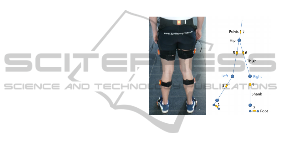
2.2.1 Experimental Setup
Xsens MTw sensors are attached laterally pairwise
on left and right lower limbs at shoes below knees,
at thighs, and one on back (pelvis) as shown in
figure 1. The camera was placed about 15 cm above
the floor, 5 m from and orthogonal to sagittal plane
of the subject.
Figure 1: Alignment of the sensors.
2.2.2 Evaluation
The movement of two healthy subjects, one female
and one male, mid-twenties, was observed. They
were asked to choose the speed for normal, slow and
fast walking themselves passing a distance of about
10 m twice from left to right and back. After some
time the same experiment was repeated. The
experiments were executed indoors where magnetic
field was neither homogenous nor steady state as
learned during the post-processing of data.
3 DISCUSSION AND RESULTS
This contribution is a position paper allowing to
outline questions followed by our suggestions and
current answers. Both can be treated as a source of
discussions.
Most of the results stated in the discussion
belong to sensors mounted on left or right shoe
(foot) acquired with 60 Hz; otherwise it will be
mentioned.
BIOSIGNALS2015-InternationalConferenceonBio-inspiredSystemsandSignalProcessing
302
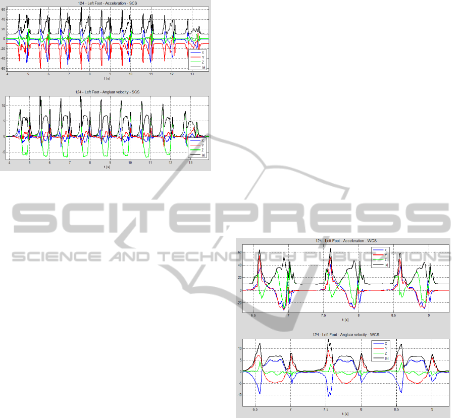
Figure 2: Acquired acceleration and angular velocity with
respect to SCS (black – length of the vector).
Do the acquired data figure out the periodicity of
movement stride by stride?
Repeating patterns obviously appear periodically,
varying little from stride to stride (see figure 1).
During stance phase acceleration is close to zero,
during swing phase large changes are typical.
Can the number of strides simply be counted?
Repeating patterns are clearly separated. Each
pattern can be assigned to one stride, so that the
number of patterns is equal to the number of strides.
The first and last step is incomplete (see last pattern
in figure 2). Both feet are side by side before and
after movement.
Is acceleration due to movement dominant in
relation to g? Is its average zero?
Yes, peaks of acceleration are up to 6 g. Walking is
characterized by change of stance and swing phases,
so that average of acceleration is zero periodically
after every second.
Is there any predominance of components of
acceleration or angular velocity?
Forward component of acceleration (direction of
movement) dominates vertical one. Lateral
component of angular velocity is dominant.
Does it seem to be possible to determine, e.g.,
length of stride or passed distance, from sensor
data without transformation into WCS?
There are several software systems like RehaWatch
and papers (e.g., Orlowski, 2013) showing that it
seems to be possible. Sensors need to be mounted
with high accuracy such that SCS coincides with
WCS at calm (stance phase). Small and short
rotations of sensors are neglected.
What can the quaternion of orientation be used
for?
The orientation is not measured, but estimated from
angular velocity, acceleration and magnetic field. If
orientation is related to WCS components of all
vectors are transformed into that inertial coordinate
system. Gravitation vector g can be eliminated.
Various angles, e.g., between sensors, vertical and
floor as well as changes of angles between sensors,
can be easily calculated.
Are the algorithms of Xsens and Madgwick
comparable?
The Xsens-Kalman-Filter (Roetenberg, 2009) is
implemented on-board the Xsens MTw sensors.
The
algorithm of Madgwick is implemented in post-
processing of acquired sensor data. Because of
heterogeneity of magnetic field orientation was
estimated only from angular velocity and
acceleration. Gait features were calculated using the
same algorithm. Differences of about 5% are
noticeable, e.g., average length of stride is mostly
larger for the Madgwick algorithm.
Figure 3: Acceleration and angular velocity with respect to
WCS (black – length of the vector).
Which definition of gait cycles is goal-oriented
with respect to the integration of the
acceleration?
There are various possibilities to determine the gait
cycle (GC). Movement starts and finishes at calm.
Any significant moment of the stance phase, where
the velocity of foot is zero, can be used as transition
point from one stride to the next one. In principle
any other significant moment, e.g., maximum of
angular velocity vector can be considered as the
transition point too. Perry (Perry, 2010) proposed the
initial contact point (IC) as the beginning of GC.
Stride-by-stride integration should start at a moment
of calm (velocity equal zero) or at least at minimum
of motion.
InertialMeasurementUnitsinGaitAnalysisApplications-Questions,SuggestionsandAnswers
303
Are there any features of data indicating
transition from stride to stride?
To find indicators of the transition point all
measured and derived data can be considered.
Manifold ideas are given in literature (e.g. Green,
2010) focussing on points nearby IC, maximum of
lateral component of angular velocity, forward
component of acceleration or angle between foot and
ground. In our algorithm the minimum of weighted
sum of acceleration and angular velocity (maximal
calm) is used. This indicator is significant for whole
stance phase, so that additional plausibility checks
should be added.
How can the direction of movement be
determined in WCS?
While z-axis of WCS coincides with vertical the
other axis are in horizontal plane. Integrating
horizontal components of acceleration velocity
vector is calculated. It defines the current direction
of movement. WCS is rotated about vertical so that
x-axis of resulting MCS coincides with direction of
movement.
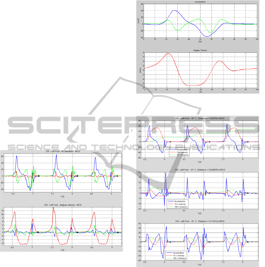
Figure 4: Acceleration and angular velocity with respect to
MCS (black–begin of integration).
Does measured stride coincide with normalized
gait pattern?
Comparing figures 4 and 5 the similarity between
gait pattern given by Perry (Perry, 2010) and our
data is obvious.
Is the integration stride-by-stride preferable in
relation to integration over the whole movement?
Choosing integration intervals, so that acceleration
average as well as initial and end velocity are equal
to zero, algorithms work very well (foot sensors). In
our algorithms we considered only inner strides,
excluding first and last half-strides (figures 6 and 7).
Figure 5: Pattern of acceleration and angular velocity
(Perry, 2010).
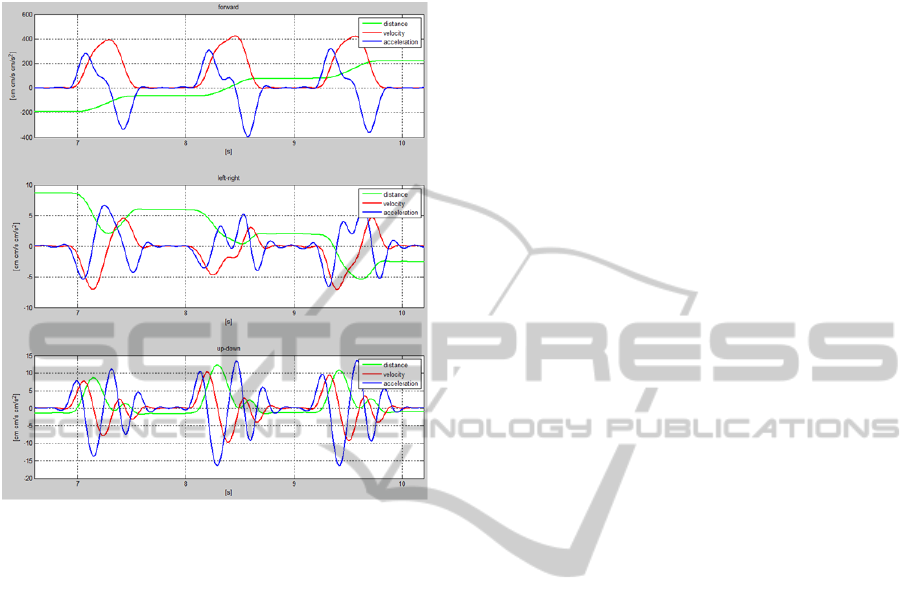
Figure 6: Measured acceleration, calculated velocity and
displacements – forward, lateral and vertical.
Are the algorithms applicable considering the
movement to other sensors?
The assumption, that initial and end velocity equals
to zero, is not fulfilled for sensors mounted above
the ankle. Their unknown minimum velocity (during
inner strides) increases with the distance from ankle.
The detection of transition points should be
improved because of absence of calm.
Is there any chance to estimate the minimum
velocity for other sensor locations?
Unknown minimum velocity can be estimated, first,
BIOSIGNALS2015-InternationalConferenceonBio-inspiredSystemsandSignalProcessing
304
based on of a model or, second, through including
first and last stride into the integration interval.
During those strides acceleration average is not zero.
Figure 7: Measured displacement, calculated acceleration,
and velocity– forward, lateral and vertical – using API
Radian.
Which and how many GC have to be involved in
the calculation of average and standard
deviation?
First and last strides are used to accelerate
(decelerate) before establishing steady movement.
To determine average only inner strides, not less
than 5, should be considered. The exact selection of
all GC and scaling to 100 % seems to be very
important.
Is there any advantage to include two or more
sensors into algorithms?
Including two or more sensors into algorithms offers
a lot of chances: to calculate angles between two
sensors (joint angles), to compare their behaviour
(symmetry) or to include improvements based on
kinematic relationships.
Does model-based calculation promise large
improvement of accuracy?
The Xsens MVN Biomech studio is based on 17
sensors and biomechanical skeleton model. It is used
in motion capture as a substitute of optical systems.
Following model-based algorithms promise
improvement of accuracy even in small systems.
4 CONCLUSIONS
The evaluation algorithms work well regarding the
data of foot sensor. Sometimes there are problems
with the accuracy of transition points between swing
and stance, i.e. starting points of the stride-by-stride
integration. Improvement of their accuracy can be
achieved including more features as well as more
sensors. At the same time calculation of average
stride will be improved and, following, the
symmetry analysis based on average GC.
Algorithms incorporating only one sensor and
processing integration stride by stride maybe applied
to other sensor location. If the absolute velocity
should be determined, the question of the steady part
of velocity has to be solved. Steady part increases
with the distance of sensors from floor. Model-based
calculation may be goal-oriented in this context, as
well as for the determination of joint angles and
symmetry indexes.
REFERENCES
Perry, J. (2010). Gait Analysis - Normal and Pathological
Function. Slack Inc.
Murray, M. (1964). Walking patterns of normal men. J
Bone Joint Surg Am, 46A:335 – 360.
Roetenberg, D., Luinge, H., and Slycke, P. (04/2009).
Xsens mvn: Full 6 dof human motion tracking using
miniature inertial sensors. XSENS TECHNOLOGY,
White Paper.
Madgwick, S., Harrison, A. J. L., and Vaidyanathan, R.
(2011). Estimation of IMU and MARG orientation
using a gradient descent algorithm. In Rehabilitation
Robotics (ICORR), 2011 IEEE International
Conference on, pages 1–7.
Orlowski, K. and Loose, H. (2014). Simple Algorithms for
the Determination of the Walking Distance based on
the Acceleration Sensor. Proceedings of
BIOSIGNALS 2014, Int. Conference on Bio-Inspired
Systems and Signal Processing, Angers, France, 03-06
March 2014, pp. 264–269.
Greene, B. (2010). An adaptive gyroscope-based
algorithm for temporal gait analysis. Med Biol Eng
Comput, 48:1251–1260.
InertialMeasurementUnitsinGaitAnalysisApplications-Questions,SuggestionsandAnswers
305
