
Discrete Sliding Mode Control for a VCM Positioning System
Kuo-Ming Chang
1
, Huang-Sheng Kung
1
and Yung-Tien Liu
2
1
Dept. of Mechanical Engineering, National Kaohsiung University of Applied Sciences, Chien-Kunng Rd.,
Kaohsiung, Taiwan
2
Dept. of Mechanical and Automation Engineering, National Kaohsiung First University of Science and Technology,
Kaohsiung, Taiwan
Keywords: Discrete Sliding Mode Control, Voice-Coil Motor (VCM), Proportional-Integral Observer, Precision
Positioning.
Abstract: In this paper, a discrete control system is implemented for a positioning device using a voice-coil motor
(VCM). The VCM positioning system is configured with a proportional-Integrator observer (PIO) and
discrete sliding mode controller (DSMC). Since the PIO could estimate system unmeasurable parameters for
compensation, the implemented control system subject to uncertainty might feature high robustness.
Through experimental examinations of step response for a sliding stage under dry friction and with a mass
of 728 g, the position error of 7.3 m was obtained for a step command of 3 mm. The percentage of position
error is 0.25%. Compared with that obtained by using the PID controller is 0.57%, the superiority of the
implemented control system is demonstrated.
1 INTRODUCTION
Positioning system is one of the fundamental
technologies that supports the development of
precision machinery such as machine tool. Recently,
due to significant progress in precision industry, the
needs for miniaturized devices are increasingly
presented. In positioning system, the direct drive that
can transmit power without gear reducer might
feature compact size. This is very attractive in
miniaturization. Therefore, the direct drives using
linear actuators such as piezoelectric actuator, piezo-
magneto actuator, ultrasonic motor, linear motor,
voice-coil motor (VCM), and static electric actuator,
etc., are well found in industry.
In this paper, the control performance of the
positioning system using the VCM is studied. The
actuation of VCM is based on the principle of
electromagnetic effect. Due to its simple structure,
compact size, and high precision, popular
applcations can be well found in hard disc drive and
automatic image foucusing device. However, these
applications are with constraint conditions of small
laod and almost friction-free motion. It is well
known that the friction force behaves remarkable
nonlinearity in microscopic motion. Therefore, the
positioning device under dry friction is very diffcult
to obtian high precision positioning. To cope with
the nonlinear system, controller desgin with
excellent robustness is very essential. In this study,
the control scheme of the discrete sliding mode
controller (DSMC) coupled with proportional-
integrator observer (PIO) is proposed for the VCM
positioning system under dry friction. The proposed
DSMC coupled with PIO is aimed at improving
robustness of the positioning system and providing
compensating function for external disturbances.
Relating to the controller design, a PIO was
verified as effective in estimating system state and
disturbance (Hsu, 2007). Regarding the DSMC, two
approximation laws of exponential and variable rate
were examined. Due to the drawbacks of current
approximation laws, two new approximation laws
being capable of reducing control chattering
phenomenon of switching surface were proposed.
Based on numerical simulations, a more stable
system locating at the origin was verified (Yan,
2006). Moreover, an adaptive DSMC coupled with
new exponential approximation law was proposed.
This system was shown as stable at the origin and
successfully applied to a DC motor driving system
capable of tracing a reference signal (Lizhong, 2007).
Different to the control algorithm, the switching
control of delay time was focused for examining the
465
Chang K., Kung H. and Liu Y..
Discrete Sliding Mode Control for a VCM Positioning System.
DOI: 10.5220/0005511204650472
In Proceedings of the 12th International Conference on Informatics in Control, Automation and Robotics (ICINCO-2015), pages 465-472
ISBN: 978-989-758-122-9
Copyright
c
2015 SCITEPRESS (Science and Technology Publications, Lda.)
DSMC. Based on the Lyapunov function, a
sufficient condition was given for designing a
controller, which could drive the system moving to
the sliding surface and guarantee the existence of the
sliding surface. Through numerical examination, the
effectiveness of the system having controllability
was demonstrated (Yu, 2013). In addition, the
DSMC being applied to a higher-order system plus
delay time was proposed. Based on the Lyapunov
function, a stable existing condition of sliding mode
was obtained. This method without the need of
reducing system order could obtain better control
and tracing performance compared to that using the
PID controller (Khandekar, 2013). Recently, the
DSMC was proposed for precision position control
of the piezoelectric actuating system. A model was
derived for compensating the hysteresis effect.
Through experimental examination, the proposed
DSMC was verified with more excellent
performance by comparing with that using the PID
controller (Xu, 2013).
Relating to the positioning device using the
VCM, a method of simultaneous perturbation
stochastic approximation (SPSA) was used to
suitably tune the PID gains for the VCM positioning
system. Through experimental examination, a more
stable and faster positioning performance could be
obtained (Ming, 2005). To determine the optimal
actuating condtion, the nonlinear double dynamic
Taguchi Method was applied to the combined piezo-
VCM actuating system (Liu, 2007). A new type of
VCM having shorted turn was developed. This type
of VCM featured faster rising time in establishing
magnetic field, thus with higher acceleration (Liu,
2010). A neural network based on radial basis
function and coupled with the PID was proposed for
the VCM positioning system. Through numerical
simuations, excellent robustness of the system was
shown (Gao, 2011). Through the above-mentioned
literature survey, the sliding mode control (SMC)
having excellent roubstness can be widely fouond in
various applications. The proposed control sheme in
this paper will be verified as effective for the system
subject to high nonlinearity and external disturbance
through the following approaches.
2 PHYSICAL MODEL
In this section, main components of the VCM
positioning system are described, and then the
physical model is established, which will be used for
controller design.
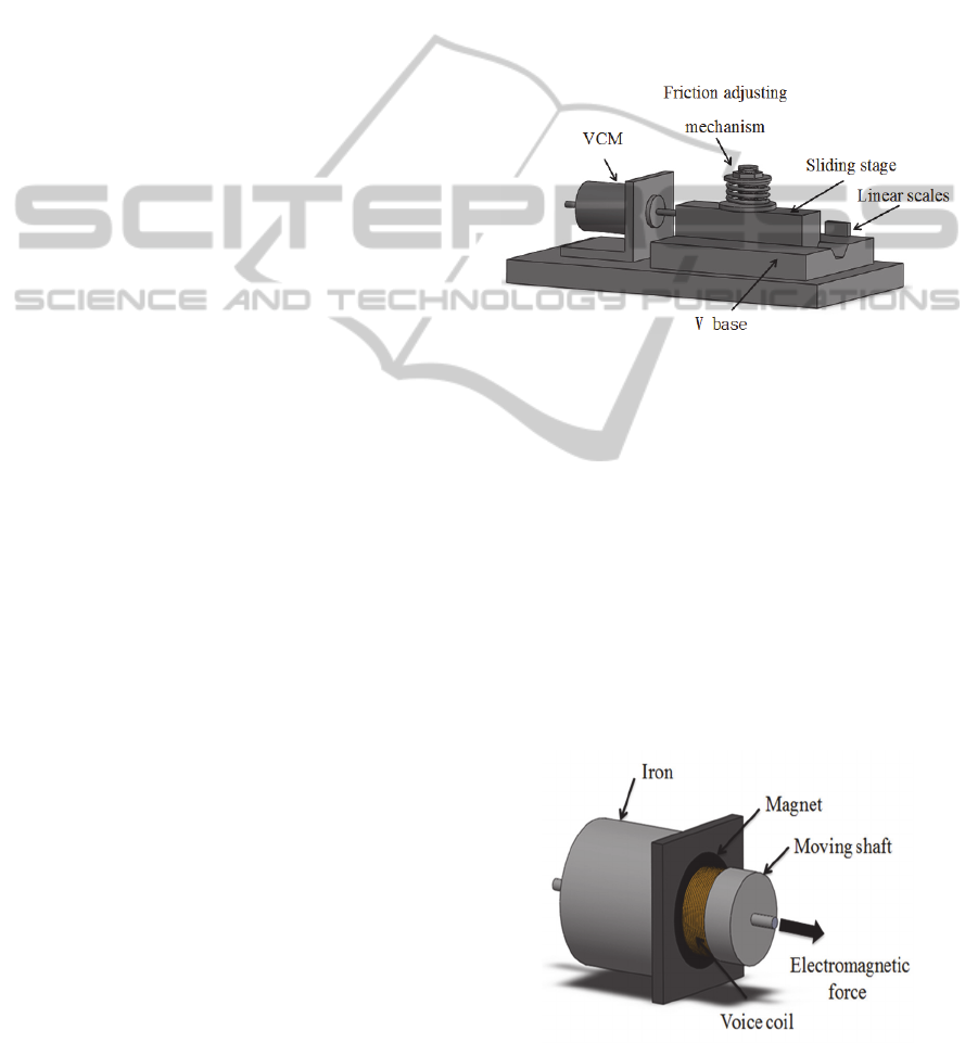
2.1 Positioning Device
Figure 1 shows the experimental setup for
examining the positioning device using the VCM.
The main components of the positioning system
include a VCM, a sliding stage, and a frictional
adjusting mechanism. The sliding stage having a
mass of 728 g and with a dimension of 35×25×130
mm
3
is set on a V-grooved base for the motion with
one degree-of-freedom. A linear encoder with a
resolution of 5 nm is mounted beside the sliding
stage
.
Figure 1: Main components of the VCM positioning
system.
2.2 VCM Model
The VCM used is a linear actuator featuring
compact size, high precision, and high response
actuating ability. Figure 2 shows the schematic
drawing of the VCM structure. The equivalent
circuit based on the motor structure can be depicted
as shown in Figure 3, where
vcm
V
is the applied
voltage for the VCM,
i
is coil current, R is coil
resistance,
L is coil inductance,
m
e
is back
electromotive force(emf), and
x
is the displacement
of the moving shaft.
Figure 2: Schematic drawing of VCM.
ICINCO2015-12thInternationalConferenceonInformaticsinControl,AutomationandRobotics
466
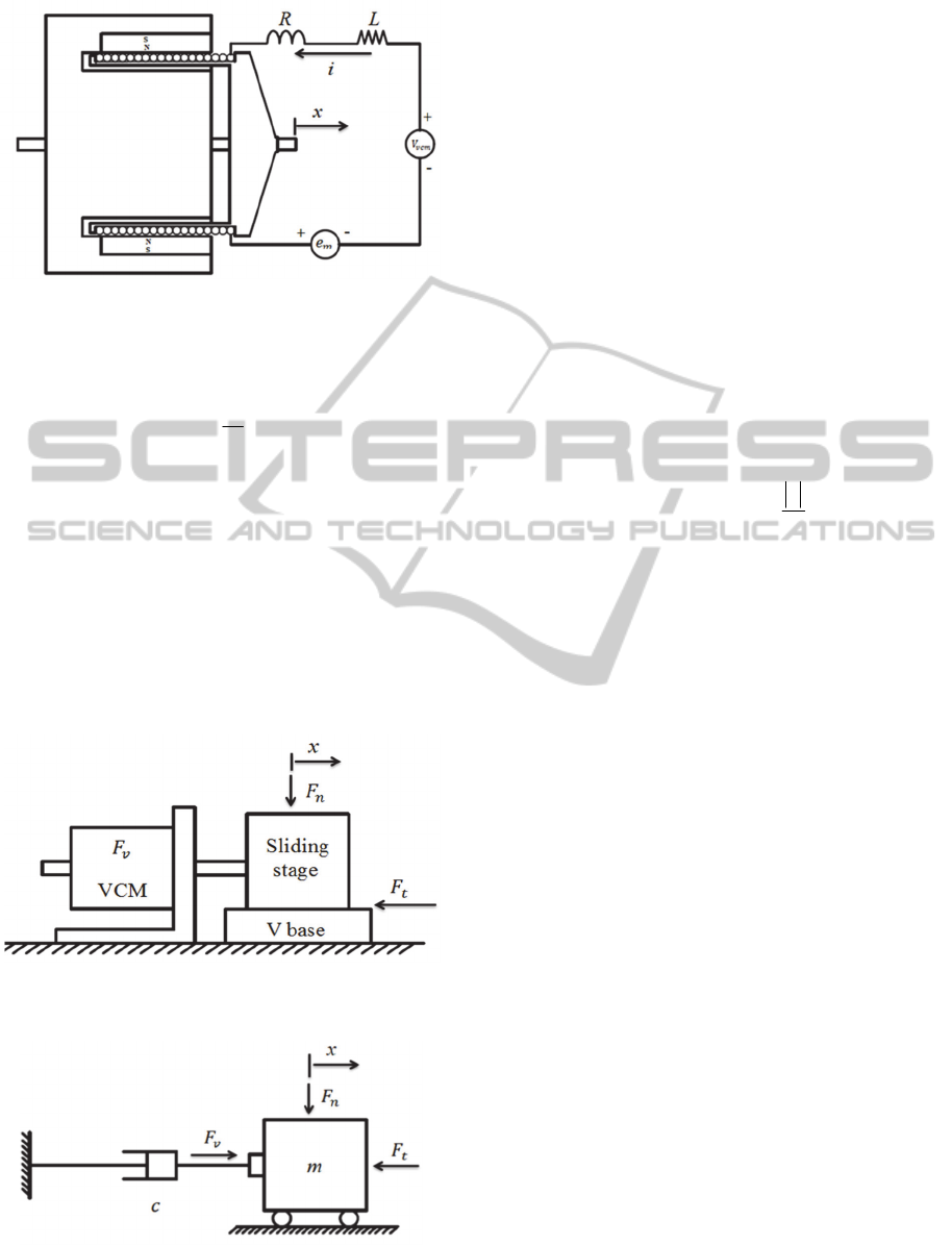
Figure 3: Equivalent electric circuit of VCM.
According to the Kirchhoff’s voltage law, the
equivalent circuit can be expressed as follows,
xKe
e
dt
di
LRiV
mm
mvcm
(1)
where
m
K
is a back emf constant, and
x
is a time
derivative of displacement, i.e., the speed of the
moving shaft.
2.3 Positioning System Model
Referring to the schematic drawing shown in Figure
1, a brief drawing expressing the main components
is shown in Figure 4.
Figure 4: Main components of the VCM positioning
system.
Figure 5: Free diagram of the VCM positioning system.
Focusing on the physical parameters, the model of
the positioning device can be depicted as shown in
Figure 5, where
m
is the mass of the sliding stage,
c
is the damping coefficient representing the nature
of the VCM,
n
F
is the normal force subjected to the
frictional adjusting device, and
t
F
is the dry
frictional force existing between the sliding surfaces.
According to the Newton’s second law, a dynamic
equation can be derived as follows,
iKF
FFxcxm
vv
tv
(2)
where
v
F
is the electromotive force generated by
the VCM, and
v
K
is a force constant;
t
F
can be
represented by a nonlinear continuous equation as
follows,
])(exp[)()(
)sgn()(
2
s
ksk
nt
x
x
x
xxFxF
(3)
where
n
F
is the total normal force,
is the viscous
damping coefficient,
s
x
represents a reference
velocity and shows the sensitivity level of the sliding
velocity affecting on the frictional coefficient, and
k
and
s
are kinematic and static friction
coefficients, respectively.
2.4 State Variables
In this study, the objective is to precisely control the
displacement of sliding stage via the controlled
voltage, V
vcm
for the VCM. The state variables
relating the positioning system are given as,
xx
1
, the displacement of sliding stage
xx
2
, the speed of sliding stage
ix
3
, the coil current of VCM
vcm
Vu
, the applied voltage for VCM
Using the state variables, Eqs. (1) and (2) can be
represented by the following forms,
233
322
xKxLRxu
FxKcxxm
m
tv
(4)
Eq. (4) is rearranged into the state equation as
follows,
DiscreteSlidingModeControlforaVCMPositioningSystem
467

t
m
v
F
m
u
L
x
x
x
L
R
L
K
m
K
m
c
x
x
x
0
1
0
1
0
0
0
0
010
3
2
1
3
2
1
(5)
Table 1: Parameters of the VCM positioning system.
Symbol Unit Value
m kg 0.63
c Ns/m 1.778
L H 94×10
-3
R Ω 3.657
K
V
N/A 4.029
K
m
V/(m/s) 4.029
k
0.25
s
0.3
F
n
N 6.18
s
x
m/s 0.001
0.4
With the parameters listed in Table 1 (Liu, 2005),
the continuous state equation is transformed into the
discrete state equation by using MATLAB package
with the zero-order hold (ZOH) input and sampling
period of 0.01 s.
du
kx
kx
kx
kx
kx
kx
08773.0
002965.0
1084610.7
08773.0
002965.0
10023.1
)(
)(
)(
0.6672 0.3482- 0
0.05195 0.9603 0
0.002787 0.009819 1
)1(
)1(
)1(
55
3
2
1
3
2
1
(6)
where u and d are the controlled input and external
disturbance, respectively.
3 CONTROLLER DESIGN
3.1 Proportional-Integral Observer
Considering Eq. (6), the state equation can be
expressed in the form as,
)()(
)()()()1(
kHxky
kEdkBukAxkx
(7)
where x(k) = [x
1
(k) x
2
(k) x
3
(k)]
T
represents state
vector,
nn
A
is the system matrix,
1
n
B
is
an input vector,
1
n
E
is an error vector, u(k) is
the controlled input, d(k) is an external disturbance,
n
H
1
is an output vector, and y(k) is the system
output. In this study, a proportional-integral observer
(PIO) is proposed to estimate unknown system states
and external disturbance of the VCM positioning
system. The structure of the PIO is given as,
)](
ˆ
)([)(
ˆ
)1(
ˆ
)(
ˆ
)(
)(
ˆ
)](
ˆ
)([)()1(
ˆ
)1(
ˆ
2
1
kykyLkdkd
kxHky
kdEkykyLkBukxAkx
+
(8)
where
1
1
n
L
and
2
L
are the designed gains
of the PIO,
)(
ˆ
kx
and
)(
ˆ
kd
are the observed values
of the system states and external disturbance. The
observed error vector of system state and the
observed error of system output are defined as
)(
ˆ
)()( kxkxke
and
)(
ˆ
)()(
~
kykyky
,
respectively. From Eqs. (7) and (8), the error term
can be derived as,
(9)
Similarly, let
)(
ˆ
)()( kdkdk
, then
)(k
can be
expressed as,
(10)
Rearrange Eqs. (9) and (10) into state equations as,
)(
)(
)(
)(
0
~
)(
)(
)(
)()1(
0
)(
)(
)1(
)1(
12
1
k
ke
G
k
ke
Hy
k
ke
LGM
kdkdk
ke
IHL
EHLA
k
ke
(11)
where
1
0
I
EA
M
,
TTT
LLL ] [
21
, and
]0 [HG
.
)(
ˆ
)()()(
)(
ˆ
))(
ˆ
)(( )(
ˆ
)()(
)(
ˆ
))(
ˆ
)(()(
)(
ˆ
)()()(
)1(
ˆ
)1()1(
1
1
1
kdEkEdkeHLA
kdEky
kyLkxAkEdkAx
kdEkykyLkBu
kxAkEdkBukAx
kxkxke
))()1(()()(
))(
ˆ
)1(
ˆ
(
))()1(()(
)1(
ˆ
)1()1(
2
kdkdkHeLk
kdkd
kdkdk
kdkdk
ICINCO2015-12thInternationalConferenceonInformaticsinControl,AutomationandRobotics
468
From Eq. (11), if
),(
GM
is observable, the gain of
observer L could be designed by the pole-placement
method such that the eigenvalues of the matrix
LGM
might lie in the unit circle, resulting in
asymptotically stable control of the positioning
system.
3.2 Design of Sliding Mode Controller
The controller is implemented by the DSMC
coupled with PIO. In designing the controller, at first,
the sliding surface is constructed based on the error
term between the reference values and the estimated
state variables from the PIO; then, the control input
u is derived based on the estimated state variables
coupled with the approaching law provided in the
work (Li, 2011). The approaching law is expressed
as
)(sgn)1)(ln()()1()1( ksTksksTks
(12)
where
10 T
and
10 T
.
If the reference target is given as
d
x
, and the
error between the reference target and the system
state is expressed as
d
xkxke )(
ˆ
)(
ˆ
, then the
sliding surface can be designed as:
123
ˆˆ
() () (() ())
( )
d
sk cek cxk x k
cc c ck
(13)
Using Eqs. (8), (12), and (13), the control input
)(ku
is to be determined. Eq. (12) can be rewritten
as:
)()(
ˆ
)](
ˆ
)([)()(
ˆ
))1()1(
ˆ
(
)1(
ˆ
)1(
1
kcxkdcE
kykycLkcBukxcA
kxkxc
kecks
d
d
(14)
Based on Eq. (14), the control law is derived as
)]1(
)(
ˆ
))(
ˆ
)(()(
ˆ
)(sgn1))(ln()(
ˆ
)1[()()(
1
1
kcx
kdcEkykycLkxcA
ksTksksTcBku
d
(15)
4 EXPERIMENTAL RESULTS
To experimentally examine the control performance
of the VCM positioning system, control experiments
based on a step command of 3 mm were performed
for both the traditional PID controller and the
proposed control scheme. Performance comparison
is carried out in the following sections.
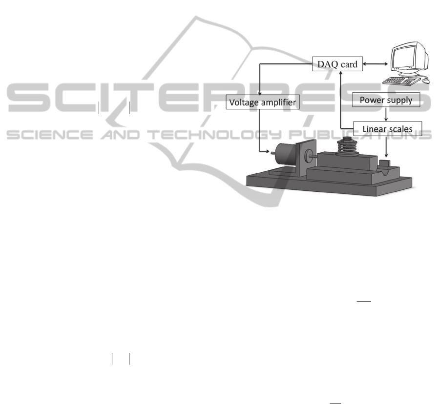
4.1 Configuration of Positioning
System
The control system for performing positioning
practice is shown in Figure 6. A 16-bit DAQ card is
used to send the control signal via amplifier to the
VCM and decode the position information from the
linear encoder (scale). The control program is
implemented with the LabVIEW package which is
commercially available software.
Figure 6: Experimental configuration of the VCM
positioning system.
4.2 PID Controls
The control input of the PID controller can be
expressed as:
dt
de
KdteKeKu
d
t
ip
1
0
11
(16)
where
)(
1 d
xxQe
with a constant vector
]001[Q
, is the system output tracking error;
P
K
,
i
K
, and
d
K
are the proportional, integral, and
derivative gains, respectively. For cotrol practice,
Eq. (16) is transferred to the discrete form as
)]1()([)()()(
11
0
11
keke
T
K
ieTKkeKku
s
d
k
i
sip
(16)
The initial conditions of the PID control system
were given as
0)0(
1
x
,
0)0(
2
x
, and
0)0(
3
x
.
The PID gains were suitably tuned as
1380
p
K
,
720
i
K
,
8.3
d
K
. To prevent the VCM from
damage, the control input was limited in the range of
3 V.
DiscreteSlidingModeControlforaVCMPositioningSystem
469
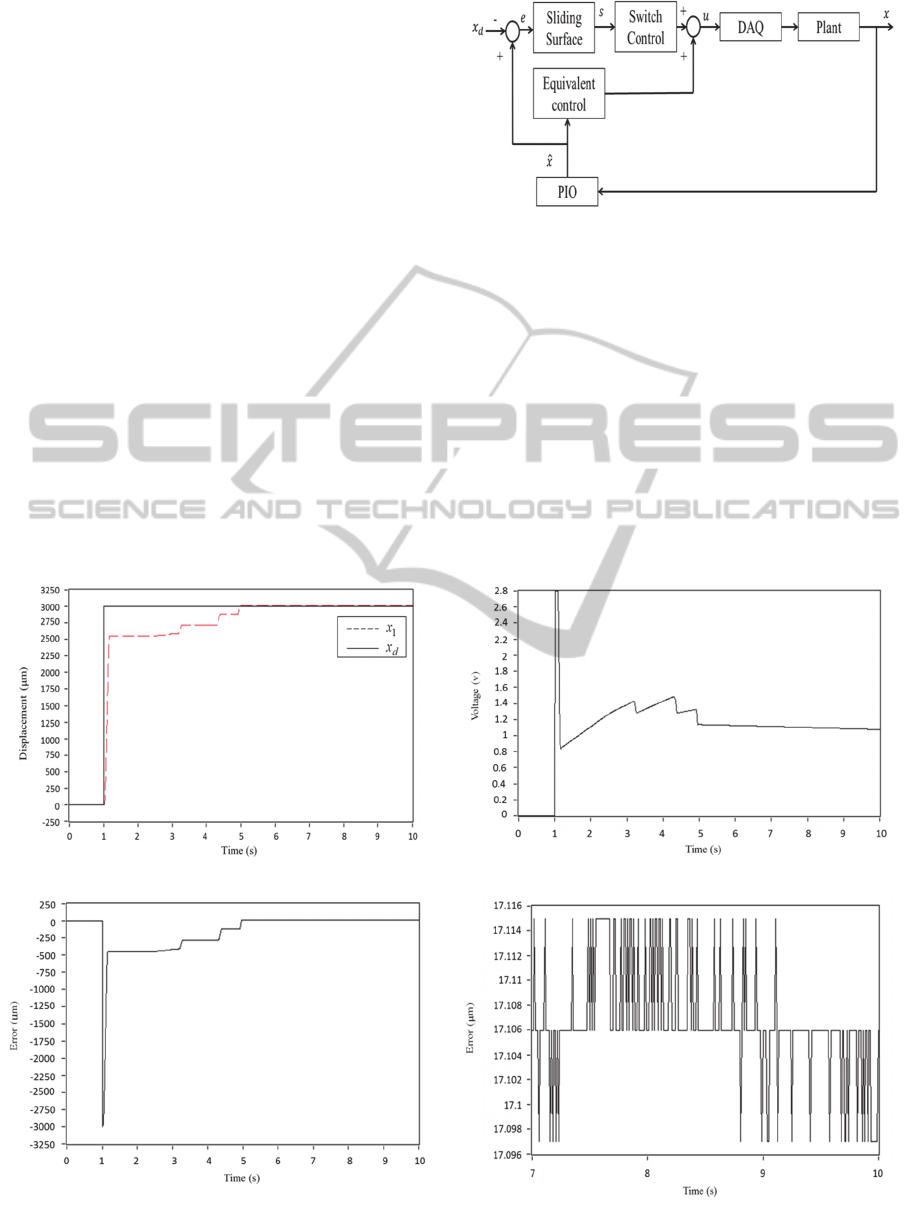
Figure 7 shows the experimental results of the
PID control under a step command of 3 mm. From
the displacement shown in Figure 7(a), the VCM
could reach the target position at time 5.2 s.
However, the sliding stage behaved significantly
unsmooth motion. For example, the sliding stage
sticked to the slidng surface even though the control
command shown in Figure 7(c) was increasingly
given during the time interval of 1.2 s to 2.8 s. This
also could be seen from Figure 7(b) showing the
time history of position error. From the enlarged
position error in the time interval of 7 s to 10 s, the
maximum error was recoded as 17.1 μm with an
error percentage of 0.57%.
4.3 DSMC Coupled with PIO
Figure 8 shows the experimental configuration of the
VCM positioning system based on the DSMC
coupled with PIO. The program was implemented
with the LabVIEW package.
The initial conditions were the same as that of
the PID control system, i.e.,
0)0(
1
x
,
0)0(
2
x
,
and
0)0(
3
x
. The designed parameters were
Figure 7: Configuration of the DSMC coupled with PIO.
determined as
]4.3 2.3 920[
c
,
0.001T
,
and
0.85T
.
Figure 9 shows the experimental results of the
DSMC coupled with PIO. From the displacement
shown in Figure 9(a), the VCM could reach the
target position at time 3 s, which was faster than that
using the PID controller. Although the control input
was varying a large range of positve and negative
voltages as shown in Figure 9(b), a smooth motion
could be found from the displacement and the
position error shown in Figure 9(c ). Also, from the
enlarged position error between the time interval of
(a) Dispacement of the sliding stage
(b) Control input
(c) Pisition error
(d) Enlarged pisition error in time interval of 7 s to 10 s
Figure 8: Experimental results of the PID controller.
ICINCO2015-12thInternationalConferenceonInformaticsinControl,AutomationandRobotics
470
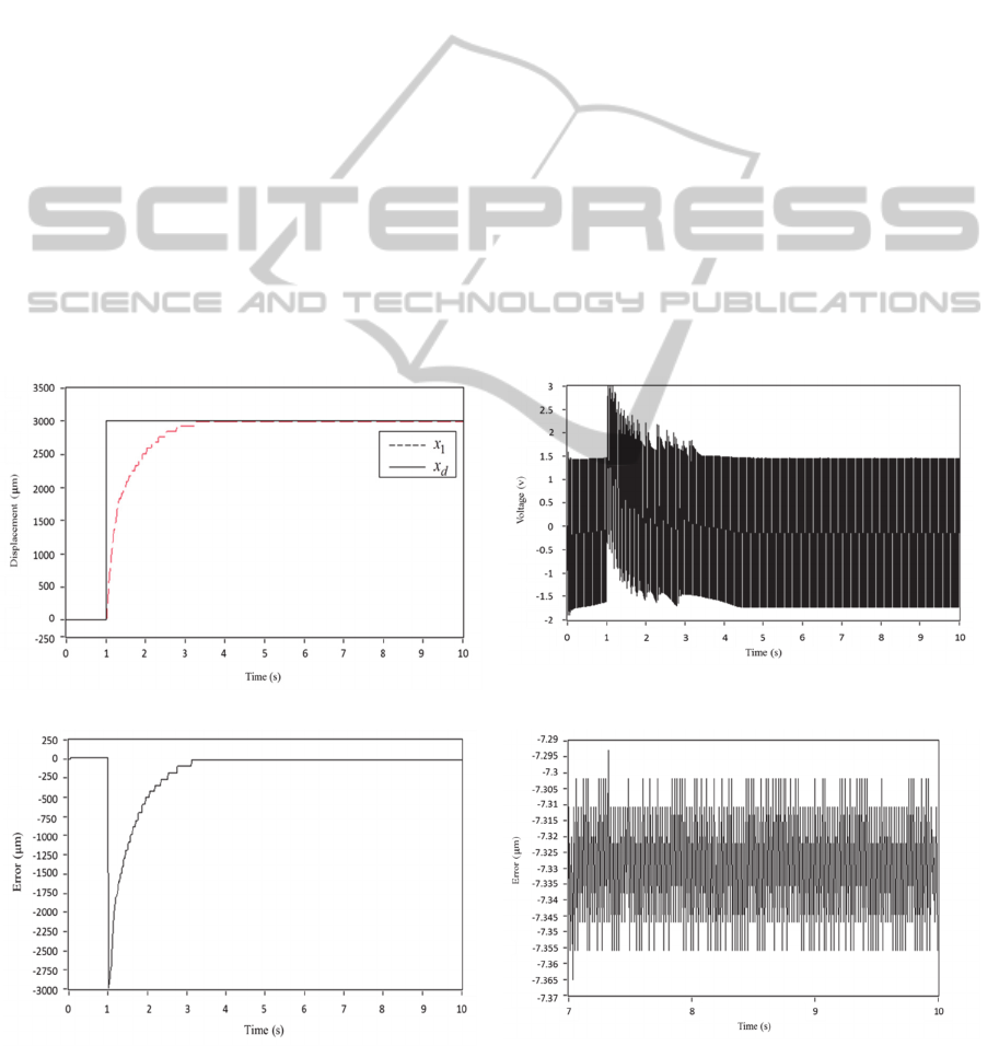
7 s to 10 s, the maximum error was recoded as 7.3
μm with an error percentage of 0.25%. These results
revealed that the control performace using the
proposed control scheme was superior to that using
the PID controller.
5 CONCLUSIONS
In this paper, the DSMC coupled with PIO was
implemented to the applicaiton of the VCM
positioning system. Through experimental
examinations, the VCM positioning system using the
proposed control scheme could reach a position error
of 7.3 μm with an error percentage of 0.25%, and a
smooth motion control was obtained. Compared with
that using the traditional PID controller, the propsed
control scheme having significant performance
improvement in positioning error and smooth motion
was verifeid.
ACKNOWLEDGEMENTS
The financial supports from the Ministry of Science and
Technology (MOST) of the Republic of China with
grant numbers of MOST 103-2221-E-327-025 and
MOST 103-2221-E-151-036 are gratefully
acknowledged.
REFERENCES
Hsu, C. C., 2007. Development of the force control system
for a coil motor, Master Thesis, Natioanl Cheng Kung
University, Taiwan.
Yan, Z., Jing, Y. W., Yang, G. H., 2006. Design of
approximation law for discrete-time variable structure
control systems. IEEE Conference on Decision and
Control 45th, pp.4969-4973.
Lizhong, S., Huang, P., 2007. Adaptive discrete-time
sliding mode control of brushless DC servomotors.
IEEE Conference on Industrial Electronics and
Applications, 2nd, pp.1101-1103.
Yu, X., 2013. Sliding mode control of discrete-time
switched systems with time-delay. Journal of the
Franklin Institute, vol.350, pp.19-33.
(a) Dispacement of the sliding stage
(b) Control input
(c) Pisition error
(d) Enlarged pisition error in time interval of 7 s to 10 s
Figure 9: Experimental results of the DSMC coupled with PIO controller.
DiscreteSlidingModeControlforaVCMPositioningSystem
471

Khandekar, A. A., Malwatkar, G. M., Patre, B. M., 2013.
Discrete sliding mode control for robust tracking of
higher order delay time systems with experimental
application. ISA transactions, vol.52, pp. 36-44.
Xu, Q., 2013. New discrete-time sliding mode control for a
piezoelectric actuation system. IEEE Conference on
Information and Automation, Yinchuan, China, August
, pp.904-909.
Ming, L. W., 2005. Voice Coil Motor Control via PID
Based on Simultaneous Perturbation Stochastic
Approximation Algorithm, Master Thesis, Chung
Yuan Christian University, Taiwan.
Liu, Y. T., Fung, R. F., Wang, C. C. 2007. Application of
the nonlinear double-dynamic Taguchi method to the
precision positioning device using combined piezo-
VCM actuator. IEEE Transactions on Ultrasonics,
Ferroelectrics, and Frequency Control, vol.54,
pp,240-250.
Liu, T. S., Yeh, C. W., 2010. Positioning control of voice
coil motor with shorted turn. Proceedings of the
Mediterranean Electrotechnical Conference, pp.1150-
1158.
Gao, Y., 2011. Active disturbance-rejection control of
voice coil motor based on RBF neural network. IEEE
Communications and Networks, pp.3895-3898.
Liu, Y. T., Fung, R. F., Wang, C. C., 2005. Precision
position control using combined piezo-VCM actuators.
Precision Engineering, vol.29, pp.411-422.
Li, J. Z., 2011. The study of proportional-integral
observer-based discrete sliding mode control, Master
Thesis, Natioanl Kaohsiung University of Applied
Sciences, Taiwan.
ICINCO2015-12thInternationalConferenceonInformaticsinControl,AutomationandRobotics
472
