
Pulley-type Ring Resonator and Optimization
Dong-Po Cai
1
, Chii-Chang Chen
1*
and Chien-Chieh Lee
2
1
Department of Optics and Photonics, National Central University, 32001 Jhongli, Taiwan
2
Optical Sciences Center, National Central University, 32001 Jhongli, Taiwan
Keywords: Ring Resonators, Nano-optics.
Abstract: In this work, we propose a guideline to design the high Q-factor ring resonators. To keep the optical energy
in the ring, the radiation loss of the ring should be reduced. The difference of the propagation constant
between the bus waveguide and the ring should be enlarged to prevent from the light in ring to be coupled
back to the bus waveguide. The phase difference of the light between the bus waveguide and ring should be
adjusted to obtain the destructive interference at the output port (critical coupling). From these points
mentioned above, we compare the 6 types of ring resonators. We conclude that the high Q-factor pulley-
type ring resonator can be more easily designed. The experimental Q-factor of the pulley-type ring
resonators with ring radius of only 4.43µm can be obtained up to 1.73×10
5
.
1 INTRODUCTION
The microring resonator is an important and
versatile integrated optics component. For example,
several devices such as filter (Little et al., 1997),
gyroscope (Matsko et al., 2004) and optical switch
(Almeida and Lipson, 2005) can be constructed by
the microring resonator. In the past decade, several
types of microring resonator are developed such as
the single microring with single bus waveguide
(Terrel et al., 2009) or double bus waveguides
(Nawrocka et al., 2006), the racetrack type (Menon
et al., 2004) and the multiple microrings type (Poon
et al., 2004). However, to decrease the device
dimension, the reduction of the ring size is required.
The disadvantage of above microring structures is
the huge bending or radiation loss from the
microring resulting in the lower Q-factor. In order to
obtain the high Q-factor, the size of the above
microring structures must be increased to reduce the
bending loss or radiation loss. The microdisk and
microring with the pulley-type coupling
configuration, pulley coupler, have been reported for
the applications of integrated optical isolators and
sensor devices in Ref. (Hu et al., 2008) and
(Hosseini et al., 2010) respectively. The Q-factor of
the ring resonators with pulley-coupler has been
reported to be 10,000 to 210,000, respectively.
However, the performance of the pulley-type ring
resonators has not been compared to that of the other
types of ring resonators.
In this work, we propose a guideline to design
the high Q-factor ring resonators. We compare the 6
types of ring resonators. We conclude that the high
Q-factor pulley-type ring resonator can be more
easily designed.
2 SIMULATION
To design the high Q-factor ring resonators, the
optical energy should be kept in the ring. First, the
radiation loss of the ring should be reduced.
Secondly, the difference of the propagation constant
between the bus waveguide and the ring should be
enlarged to prevent from the light in ring to be
coupled back to the bus waveguide.
Thirdly, the phase difference of the light between
the bus waveguide and ring should be adjusted to
obtain the destructive interference at the output port
(critical coupling). Fine tune of the dimensions of
the ring should be performed.
Table 1 shows the dimension parameters that can
be varied for finely tuning the ring resonators to
obtain the high Q-factor. We can observe that only
the bus waveguide width change one property of the
ring resonators, . Therefore, in this work we finely
tune the performance of the ring resonators by
changing the bus waveguide width.
25
Cai D., Chen C. and Lee C..
Pulley-type Ring Resonator and Optimization.
DOI: 10.5220/0005523800250028
In Proceedings of the 6th International Conference on Optical Communication Systems (OPTICS-2015), pages 25-28
ISBN: 978-989-758-116-8
Copyright
c
2015 SCITEPRESS (Science and Technology Publications, Lda.)
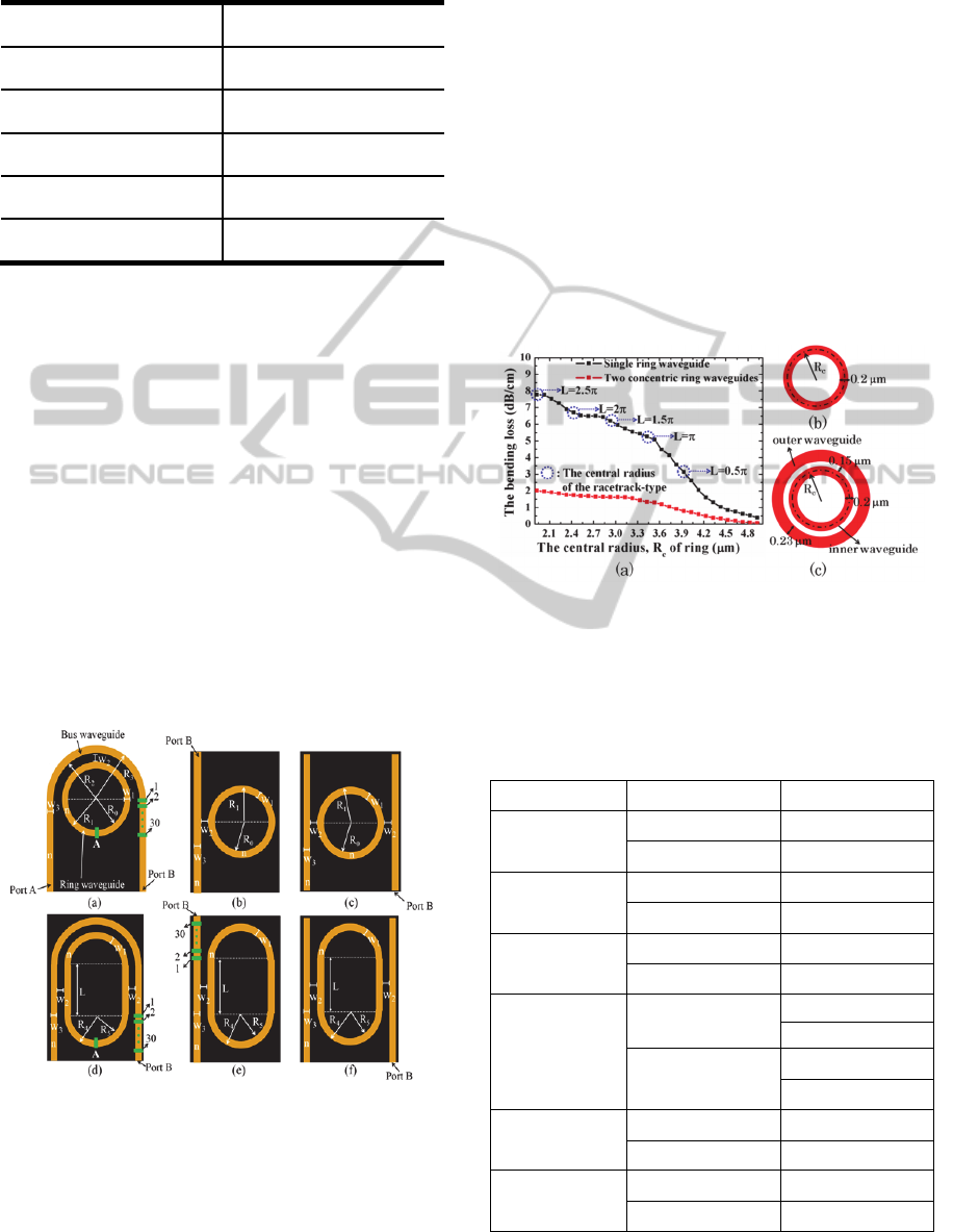
Table 1: Dimension parameter of ring resonators and the
influences on the properties of ring resonators.
Dimension Parameters Influences
Ring radius
L, , λ
Gap
, κ, λ
Ring waveguide width
L, , λ
Bus waveguide width
Refractive index
λ,
L: the length of cavity, β: the propagation constant
: the resonant wavelength, : the coupling coefficient.
In this study, we adopt the 2-D finite-difference
time- domain method (2-D FDTD) to investigate the
energy decay in the ring resonators. The microring
resonator of the 6 types to be studied are
schematically shown in Fig. 1(a)-(e).
The refractive index of bus waveguides and the
ring is 3.48. The background refractive index is
unity. The inner radius, R0, and the outer radius, R1,
of the ring are 4.33m and 4.53m, respectively.
The inner radius, R2, and outer radius, R3, of the
curved bus waveguide is 4.68m and 4.88m. The
ring waveguide width, d1, and the bus waveguide
width, d3, are both 0.2m. The gap, d2, between the
ring and the bus waveguide is 0.15m. The light at
the wavelength of 1550nm in the TM polarization is
launched into the waveguide.
Figure 1: (a) Schematic drawing of the pulley-type
microring resonator. (b)-(e) Schematic drawing of the
various ring resonators.
Fig. 2(a) shows the bending loss per propagation
distance of the single ring waveguide and the two
concentric ring waveguides. The single ring
waveguide with the central radius, Rc, defined as
(R0+R1)/2 is schematically shown in Fig. 2(b). Fig.
2(c) illustrates the two concentric ring waveguides.
The gap between two waveguides is 0.15 m. The
inner and outer waveguide widths are 0.2m and
0.23 m, respectively. We launch an impulsed light
in the ring and to obtain the bending loss per
propagation distance of ring waveguide.
We can observe that the bending loss of the two
concentric ring waveguides is lower than that of the
single ring waveguide. This is due to the fact that the
outer waveguide of the concentric ring waveguides
can collect the light of the radiation loss of the inner
waveguide. Since the light in the outer waveguide
can be coupled back to the inner waveguide, the
bending loss of the ring can be reduced.
Figure 2: (a) Bending loss per propagation distance of
single ring waveguide and two concentric ring waveguides
for different Rc. (b) and (c) Schematic drawing of single
ring waveguide and two concentric ring waveguides,
respectively.
Table 2: Q-factors and Db for the 6 ring resonator
structures illustrated in Figure 1.
Structure Q-factor
Fig. 1(a)
7×10
5
3.4372
1.4×10
3
1.2103
Fig. 1(b)
1.24×10
5
10.2
1.98×10
4
5.367
Fig. 1(c)
7.16×10
4
10.2
9.06×10
3
5.367
Fig. 1(d)
3.6×10
4
4.465
0
5.8×10
3
1.355
0.2418
Fig. 1(e)
2.83×10
5
9.6078
5.86×10
3
0
Fig. 1(f)
1.79×10
5
9.7684
3.6×10
3
0
OPTICS2015-InternationalConferenceonOpticalCommunicationSystems
26
3 FABRICATION AND
CHARACTERISATION
We fabricate the pulley-type microring resonators by
using the e-beam lithography. The SOI with the top
silicon layer of 250 nm thick and the buried oxide
layer of 3m thick is used. The sample is prebaked
on the hotplate with 90
o
C during 1 minute. The E-
beam writer, RAITH150-TWO, with the
acceleration voltage 20 kV and the aperture size of
30m is employed to define the pattern of the
pulley-type ring resonators. The ring waveguide
width, the gap width, the bus waveguide width and
the radius of ring are chosen to be 0.2, 0.15, 0.23
and 4.43m, respectively. The grating coupler is
employed to couple the light into and out of the ring
resonators with the optical fibers. The period of
grating is 620 nm. The duty cycle of grating
couplers is gradually varied from 13 % to 50 % with
the step of 1.6 %. The taper segments with the
length of 150m are used to connect the bus
waveguide and the grating coupler. The developer
(MF-319: TMAH=99%: 1%) is used to remove the
unexposed photoresist during 20 seconds. After
developing, the sample is rinsed by deionized water
(DI water) during 20 seconds to remove the residual
developer. Finally, the sample is dried by the N2 gas.
Before etching, the sample is hard baked on the
hotplate with 100
o
C during 10 minutes to firm the
photoresist. The pattern of the pulley-type ring
resonators and the grating couplers are transferred to
the SOI wafer by the reactive-ion etching (RIE) with
the power of 160 W, the working pressure of 80
mTorr, CF
4
(48 SCCM) (SCCM stands for cubic
centimeter per minute at standard conditions for
temperature and pressure) and CHF
3
(12 SCCM).
The etching depth of device is around 150 nm. After
the dry etching, the acetone (ACE) is used to remove
the residual photoresist. The scanning electron
micrograph (SEM) image of the pulley-type ring
resonator, the grating coupler and the schematic
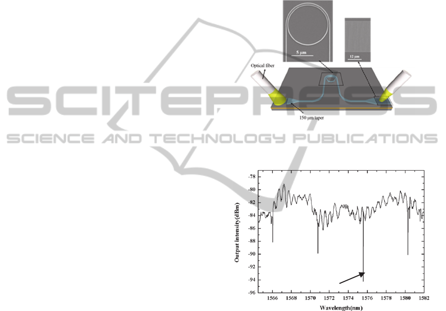
structure of device are shown in Fig. 3.
To characterize the pulley-type ring resonator,
the broadand amplified spontaneous emission (ASE)
light source and the optical spectrum analyzer are
employed.
The output power spectrum of the pulley-type
microring resonator is shown in Fig. 4. The vertical
axis is presented in dBm scale. The deepest notch is
located at 1575.65 nm as the bus waveguide width is
0.23m. The Q-factor of 1.73×10
5
is obtained by
employing the Lorentz curve fitting. The shift of the
resonance wavelength between the design and the
experimental result is around 9.69 nm due to the
fabrication error. This work shows that by changing
the bus waveguide width to achieve the critical
coupling, the maximal energy of the traveling light
at the resonance wavelength of 1575.65 nm stored in
the ring resonator can be optimized. The measured
Q-factor of 1.73×10
5
is lower than the theoretical Q-
factor of 7× 10
5
. This is due to the fact that the
roughness of the waveguide surface can scatter the
traveling light out of the pulley-type ring resonator.
Figure 3: Schematic drawing of the characterisation setup
including the SEM micrograph of the pulley-type ring
resonator and the grating couplers.
Figure 4: Measured spectrum of the pulley-type ring
resonator.
4 DISCUSSION AND
CONCLUSION
In Ref. (Hu et al., 2008); (Hosseini et al., 2010), the
microdisk with the radius of 20m is fabricated on
the As
2
S
3
platform. The Q-factors are 2.1×10
5
and
1.5×10
5
for the TM and TE modes, respectively. (Hu
et al., 2008) The Si
3
N
4
microdisk with the radius of
20m is fabricated on the SiO
2
platform. The Q-
factor characterized by the launched source in the
TE mode is 6×10
5
.(Hosseini et al., 2010) In our
work, the radius is only 4.43m. However, we can
Q=1.73x10
5
Pulley-typeRingResonatorandOptimization
27
obtain the Q-factor with the same order of
magnitude. Our result shows that the pulley-type
ring resonator can be ameliorated by enlarging
and shows the possibility to obtain the ring
resonators with higher Q factor if the ring radius is
enlarged or the sidewall roughness of the
waveguides is improved.
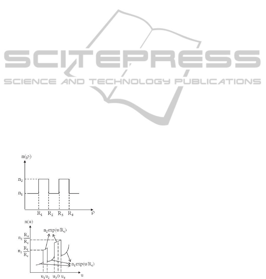
In our previous work, we propose a fast method
to calculate the coupling length of the concentrically
curved waveguides using the conformal mapping.
(Cai et al., 2012) Fig. 5 shows the schematic
refractive index profile of the concentrically curved
waveguides before and after conformal mapping.
We can observe that the effective index of the outer
waveguide is higher that of the inner waveguide.
This implies that the propagation constant of the two
curved waveguides is not inherently identical. In the
case of the directional couplers with straight
waveguides, the 100% energy coupling is not
possible. However, in the case of the ring resonators,
the critical coupling can be achieved due to the fact
that the circumference of the ring the integer
multiple of the resonant wavelength, even if the
propagation constant of the concentrically curved
waveguides is not identical. Therefore, the fine
tuning of the outer concentrically curved waveguide
width can achieve the critical coupling. Since the
effective refractive index of the outer curved
waveguide is higher than that of the inner waveguide,
the radiation loss of the ring can be reduced due to
the good optical confinement of the higher refractive
index profile of the outer curved waveguide.
(a)
(b)
Figure 5: (a) Refractive index profile of two concentrically
curved waveguides (b) Refractive index profile after
conformal mapping.
In summary, the rigorous FDTD method has
been employed to analyse the 6 types of ring
resonators. Since the bending loss per propagation
distance of the two concentrically curved
waveguides is lower than that of the single curved
waveguide, the pulley-type ring resonator can
provide lower optical loss.
In this work, we fabricate the pulley-type ring
resonator based on the SOI platform. The Q-factor
of the pulley-type ring resonator is measured to be
1.73×10
5
as the bus waveguide width of 0.23m
and the ring radius of 4.43m. The Q-factor might
be ameliorated by smoothing the sidewall of
waveguide. The high Q-factor of the pulley-type
ring resonator with tiny radius is helpful for the
miniaturization of the integrated optical devices.
REFERENCE
B. E. Little, S. T. Chu, H. A. Haus, J. Foresi, and J.-P.
Laine, J. Lightwave Technol. 15, 998 (1997).
A. B. Matsko, A. A. Savchenkov, V. S. Ilchenko, and L.
Maleki, Opt. Comm. 233, 107 (2004).
V. R. Almeida and M. Lipson, Opt. Lett. 30, 2733 (2005).
M. Terrel, Michel J. F. Digonnet, and S. Fan,
“Performance comparison of slow-light coupled-
resonator optical gyroscopes,” Laser & Photon. Rev.
3,452 (2009).
M. S. Nawrocka, T. Liu, X. Wang, and R. R. Panepucci,
“Tunable silicon microring resonator with wide free
spectral rang,” Appl. Phys. Lett. 89, 071110 (2006).
V. M. Menon, W. Tong, and S. R. Forrest, “Control of
Quality Factor and Critical Coupling in Microring
Resonators Through Integration of a Semiconductor
Optical Amplifier,” IEEE Photon. Technol. Lett. 16,
1343 (2004).
Joyce K. S. Poon, J. Scheuer, Y. Xu, and A. Yariv,
“Designing coupled-resonator optical waveguide delay
lines,” J. Opt. Soc. Am. B 21, 1665 (2004).
J. Hu, N. Carlie, N. Feng, L. Petit, A. Agarwal, K.
Richardson and L. Kimerling, “Planar waveguide-
coupled, high-index-contrast, high-Q resonator in
chalcogenide glass for sensing,” Opt. Lett., 33, 2500
(2008)
E. S. Hosseini, S. Yegnanarayanan, A. H. Atabaki, M.
Soltani and A. Adibi, “Systematic design and
fabrication of high-Q single-mode pulley-coupled
planar silicon nitride microdisk resonators at visible
wavelength,” Opt. Express, 18, 2127 (2010).
D. P. Cai, C. C. Chen, C. C. Lee, and T. D. Wang, “Study
of Coupling Length of Concentrically Curved
Waveguides,” IEEE Photon. J. 4, 80 (2012).
OPTICS2015-InternationalConferenceonOpticalCommunicationSystems
28
