
Energy-Management-as-a-Service: Mobility Aware Energy
Management for a Shared Electric Vehicle Fleet
Julien Ostermann and Falko Koetter
Fraunhofer Institute for Industrial Engineering IAO, Nobelstr. 12, 70569 Stuttgart, Germany
Keywords: Energy Management System, Electric Vehicle, Distributed Energy Resources, Cloud-based, Information
and Communication Technology, Optimal Charging, Direct Load Control.
Abstract: The combination of sustainable energy generation and transportation is one of the biggest challenges of the
21st century. In this work, an energy management system is presented which provides energy-management-
as-a-service for electric vehicle fleet operators. Energy production and price forecasts are integrated with
near real-time telematics data from a shared electric vehicle fleet, to optimize charging profiles for multiple
charging sites of fleet operators. For this purpose, system architecture and a proper optimization method
enabling different charging strategies are introduced. The presented system is finally evaluated by real
world model trails and an optimization benchmark.
1 INTRODUCTION
One of the biggest challenges of the 21st century is
the transition to sustainable transportation and
energy generation (Chu and Majumdar, 2012). The
need for ensuring sustainability is not only driven by
rising fuel cost or the increase of CO
2
emissions, but
also due to economic and political issues. In the field
of transportation, battery electric vehicles (BEV) and
plug-in hybrids (PHEV) help to reduce CO
2
emissions as well as fossil fuel dependency.
Unfortunately, using these vehicle types incurs high
investment costs, due to the cost of vehicles
themselves and the cost of charging infrastructure.
Nevertheless, these cost issues can be mitigated,
using electric vehicles (EV) in corporate car pools.
The study presented in (Plötz et al. 2014) calculates
that the total cost of ownership (TCO) of EVs is
lower compared to vehicles with internal
combustion engines (ICE) when used in corporate
vehicle fleets due to uniform driving profiles. Thus,
corporate car fleets are a field of high potential for
electric vehicle usage, especially since the study
shows that 60 percent of today’s newly registered
cars are equipped as commercial cars in Germany.
Furthermore, the German Federal Government
(German Federal Government 2009) projected a
market ramp-up of 1 million EVs by the year 2020.
The project Shared E-Fleet (Ostermann et al. 2014)
aims to leverage this potential by providing a
software solution to enable small and medium sized
enterprises which are not able to operate a sufficient
amount of EVs economically on their own. The
solution helps sharing vehicles between companies
and users, realizing cross-company electric car
pools.
Compared to conventional cars, the usage of EVs
in a corporate shared vehicle fleet imposes unique
challenges. Besides the limited range of EVs and
indispensable charging times, concurrent charging of
EVs might result in power peaks at a common
charging site that might violate local grid constrains.
Especially the operation of large fleets will not only
affect fleet operators but also energy grid operators.
These must provide the grid with a suitable amount
of energy during peak times (Clement-Nyns 2010,
Lopes et al. 2010, Deilami et al. 2011). The grid
operators fear that uncontrolled integration of a large
amount of EVs into the distribution grid might have
a huge impact on the grid stability (Lopes et al.
2010). One solution is the integration of EV fleets as
part of the smart grid. In this way, grid operators can
prevent cost intensive grid expansion given the fact,
that information and communication technologies
(ICT) are harnessed to realize coordinated charging
strategies. On the other hand, fleet operators can
utilize coordinated charging to prevent demand
peaks caused by concurrent charging of their vehicle
fleet and thus enable scheduled charging in order to
340
Ostermann, J. and Koetter, F.
Energy-Management-as-a-Service: Mobility aware energy management for a shared electric vehicle fleet.
In Proceedings of the 5th International Conference on Smart Cities and Green ICT Systems (SMARTGREENS 2016), pages 340-350
ISBN: 978-989-758-184-7
Copyright
c
2016 by SCITEPRESS – Science and Technology Publications, Lda. All rights reserved

preferably consume locally generated renewable
energy as it is produced.
In order to leverage these capabilities of EV
fleets, an energy management system (EMS) is
required which is able to easily integrate with
various system services and business processes to
provide dedicated control of the operation.
Furthermore, it enables coordinated grid to vehicle
(G2V) charging of EV fleets at multiple locations
under consideration of local and decentral energy
production. In the process, forecast services shall be
used to take into account weather-dependent
renewable energy production.
In this work, we present the results of our
research in a mobility aware intelligent energy
management aggregator, serving as an EV virtual
power plant (VPP) as part of the Shared E-Fleet
architecture. It enables a direct load control of
intelligent charging stations. Thus, a centralized
control architecture is introduced, interacting with
multiple ICT components to apply optimized
charging schedules, based on real time needs of a
shared EV fleet.
This work is structured as follows: Section 2
gives an overview of relevant related work. Section
3 introduces the use case of the project Shared E-
Fleet from an energy related viewpoint. Section 4
describes the architecture of the aggregator. In
Section 5 the applied energy optimization algorithm
is outlined. The prototype and evaluation are given
in Section 5. Finally, Section 6 concludes this work
and gives an outlook on future work.
2 RELATED WORK
Considerable research has been contributed already,
investigating the integration of all kinds of EVs into
a future smart grid. Since research in this area
started already when adaption of PHEV began, not
all work does solely concentrate on BEVs.
Nevertheless, both types of vehicles do behave the
same regarding the goal to develop coordination of
charging and smart grid integration. In (Jansen et al.
2010), the authors present a modular VPP
centralized architecture and necessary
communication protocols to realize coordinated
charging for a fleet of EVs as part of the EDISON
project. Similar approaches concerning VPP for EV
fleets with integration of distributed energy
resources (DER) were already explicitly investigated
by (Raab et al. 2011, Vandoorn et al. 2011). In
literature, two different approaches of integration of
DER are discussed. Besides VPP which aggregate
DER units to provide controllability and enable
market participation, micro grids (MG) aggregate
local DER to provide a controllable entity that can
operate in grid-connected and islanded mode
(Vandoorn et al. 2011). In both concepts, an EV
fleet acts as controllable battery storage system.
Beside energy storage systems a MG or VPP can
also include charging stations or a PV plant.
Although the MG and the VPP concepts are similar,
they can be differentiated by seeing a VPP
aggregator as virtual, software-based aggregation
and the MG as physical aggregation of DER units.
In this work, we introduce an approach, not only
focusing on a central VPP acting as aggregator but a
multi-station aggregator, being able to provide
second level control and operate multiple MGs
independently. Thus, it enables the aggregator to
consider preferences and local load management
constraints defined by the respective MG operator.
The later proposed aggregator is able to perform
smart charging. With smart charging, charging
stations are basically provided with predefined
charging profiles. These profiles have to be followed
by the battery management systems (BMS) of the
vehicle. Smart charging has the advantage to enable
charging stations and subsequently each connected
EV to defer charging processes to a later point in
time or directly control the drawn current according
to a given profile. Smart charging for EV fleets is
already addressed in previous research. For example,
in the work of Hu et al. (Hu et al. 2014),
optimization and control methods are summarized to
present an overview of this field regarding smart
charging as part of EV aggregators. The authors in
(Valogianni et al. 2014) are presenting a
management system leveraging the battery storage
capabilities provided by EVs. An extensive review
of smart charging approaches and architectures is
presented in (García-Villalobos et al. 2014).
Especially the sprawl of distributed energy
generation, energy storage systems, privately owned
photovoltaic (PV) power plants, wind power
generation, or combined heat and power-plants
(CHP) presents a challenge for future charging
aggregator systems, making support of smart
charging necessary. The flexibility of EVs as
controllable loads to mitigate uncoordinated
charging impacts was investigated in (Han et al.
2010, Saker et al. 2011, Sundström and Binding
2012, Alonso et al. 2014, Valogianni et al. 2014).
Extensive reviews regarding charge scheduling for
EVs is given by (García-Villalobos et al. 2014,
Mukherjee and Gupta, 2014).
Nonetheless, previous work considered only
Energy-Management-as-a-Service: Mobility aware energy management for a shared electric vehicle fleet
341

optimization methods isolated from productive
systems and not integrated into working prototypes.
VPP aggregators realizing smart charging as part of
a smart grid have been presented (Chynoweth et al.
2014, Lutzenberger et al. 2014, Zuccaro et al. 2014).
Additionally, various researchers developed multi
agent systems to accomplish a VPP aggregator
(Lutzenberger et al. 2014). Although the approach in
(Mültin et al. 2012) is similar to our approach, we
provide a hierarchical controlled VPP, monitoring
and controlling multiple sites as a cloud-based
solution. As proposed in (Hu et al. 2013, Mukherjee
and Gupta 2014), we orchestrate a distributed
service oriented architecture (SOA) as a cloud-based
solution, enabling the aggregator to react in near
real-time to the fleet operation. Hence, we develop a
solution for fleet operators, with the goal to enable
their fleet to participate in the smart grid, without
being dependent on solutions provided by a utility
company, as well as being flexible to scale.
3 SHARED E-FLEET SCENARIO
In the research project Shared E-Fleet (SEF) a
cloud-based solution was investigated which enables
a car fleet operator to manage and provide a fleet of
BEV across several companies at one or multiple
sites. Different works (see (Barth et al. 2000,
Delucchi and Lipman, 2001, Lee et al. 2005))
suggested that increasing the utilization of EV fleets
for example by increasing trips per day, decreases
the TCOs and make them more economic than
combustion engine vehicles regarding short range
trips. Hence, the SEF IT solution provides a system
including mandatory functionalities for car fleet
management like booking, billing and operation, to
be able to realize a corporate car sharing platform.
Compared to other already available commercial
solutions, the SEF solution was intended as an
extensible, service-based cloud-platform to integrate
various fleet management services in a highly
configurable matter, making the operator
independent of vendor specific solutions (Ostermann
et al. 2014).
Unlike state of the art solutions, in the SEF use
case, instead of booking a car, the user books a
mobility demand by defining the start and end point
and time of his business trip. Since SEF uses a
station based car sharing approach, the start and
endpoint of each mobility demand is always at a
dedicated station of the SEF system. Certainly, the
start and end station do not have to be the same.
Until one hour before the respective beginning of a
trip, a booking is not explicitly bound to one vehicle.
Only after reaching this time, it is fixed to a
dedicated vehicle. A one hour time frame was
chosen to assure the user a safe operation of the
system by this feedback and leave a margin in case
of failure. In this way, the disposition optimization
management service reschedules journeys in real
time and reacts to unforeseen issues like delayed
vehicle returns or unexpected state of charge (SOC)
at the time of return (Koetter 2015). The latter one is
especially crucial in EV fleets, since a properly
predicted SOC influences all succeeding, already
booked journeys on the same vehicle. Thus, already
booked trips may be canceled in case of unforeseen
issues. During the booking process, the disposition
optimization assesses the current schedule whether
the user request can be fulfilled even considering a
suitable buffer in time and SOC, but large deviations
of the expected SOC or return time can only be
intercepted by standby vehicles.
Thus, the platform is constantly aware of the vehicle
state. During each trip, the vehicles are monitored,
predicting their estimated return time and their SOC
based on real-time data from an on-board unit
(OBU). Future states of the vehicles at the end of a
journey can be estimated and used for future
optimization procedures. On return of a vehicle, its
user has to reconnect the vehicle to the charging
station, enabling them to recharge for the upcoming
trip.
As part of the SEF ecosystem, a service is
required for managing the charging processes and
energy demand of the vehicles according to grid
constrains and operator specification as part of a
smart grid. Considering that, an energy management
system controls the charging of the EVs at the SEF
charging sites. To perform these tasks, the following
requirements have to be fulfilled:
R1. All EVs of the fleet must always be able to
satisfy the needs of the mobility demand of the user.
Hence, the EMS is responsible for sufficiently
charged vehicles according to the journey schedules
of the disposition management. The schedules for
the vehicles must contain a predefined start and end
time as well as a consumption forecast for each
journey.
R2. Vehicle disposition schedules may change
over time. Due to unforeseen influences, vehicles
may return with different SOC or return late at the
station. The EMS has to update the charging
schedules continuously according to the current state
of the system.
R3. In order to sufficiently fulfill R1 and R2, an
algorithm is required which is capable to calculate
SMARTGREENS 2016 - 5th International Conference on Smart Cities and Green ICT Systems
342
an optimal charging schedule regarding the
constrains of the system. Thus, optimal charging
schedules have to be computed based on different
charging strategies which are ought to be selected by
the operator of the respective fleet ensuring R1 and
R2.
R4. In order to perform tasks as part of a smart
grid, the EMS is supposed to be able to monitor and
control distributed and local energy resources. A
model is required, describing the involved
components and their properties to provide
optimization algorithms with system constraint
boundaries.
R5. Especially renewable energy resources are
dependent on weather conditions. Thus, weather
conditions have to be considered during charge
scheduling. A forecasting system has to be
integrated which provides information about the
prospected energy production of individual
components.
R6. As stated in R1, the state of the complete
EMS is time dependent. The EMS has to be
provided with information about the state of all
relevant system components. The EMS has to store
these states in order to enable the user to keep track
of them at a later point in time.
R7. The EMS must integrate intelligent charging
stations which are capable of directly controlling the
output current. This way, pre-calculated charging
profiles can be applied to the EV.
R8. Furthermore, various fleet operators with
multiple fleet charging sites must be able to use and
integrate their master data management with the
EMS.
R9. The EMS must keep track of the current
energy production and EV charging at the respective
charging sites and always ensure safe operation of
the energy system by staying in system boundaries.
R10. The system must also be able to fulfil non-
functional requirements. Thus, it must be able to
scale in order to provide services to multiple users.
Robustness is required to provide services even in
case of failure. Additionally, the EMS must perform
well, even with a large amount of managed
components.
4 AGGREGATOR SYSTEM
ARCHITECTURE
In the following, we present the architecture of the
EMS, showing how it is able to provide energy-
management-as-a-service. The system architecture
of the complete SEF ecosystem for a shared EV fleet
is described in (Ostermann et al. 2014). The EMS is
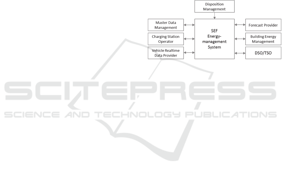
part of this ecosystem. Its system architecture is
depicted in Figure 1. The EMS is acting as central
node, integrating all mandatory components to fulfil
all previously stated requirements. All components
are integrated by connecting to their web services.
Through the integration of master data management
(MDM) services, the EMS can obtain properties of
all physical system components. Thus, by defining a
mutual data exchange interface, various MDM
systems can provide information about the deployed
EVs, the energy production resources, the charging
stations and about charging sites of the individual
fleet operator.
Figure 1: EMS system architecture.
An interface to a charging station operator (CSO)
provides the EMS with means to monitor and
control charging stations. CSO are business entities,
owning, managing, maintaining, and operating an
aggregation of charging stations. Note that EV fleet
operators can also be CSOs themselves. In order to
provide the EMS with real-time state data of the
vehicles, a external database is interconnected to the
EMS which stores telematics from vehicles.
Telematic real-time data of the vehicles might be
provided by OEMs in near future. However, today
this data is provided by third-party developers using
proprietary hardware which is amalgamated in
separate provider specific databases.
A forecast provider service supplies the EMS
with up-to-date and day-ahead energy production
forecasts. Similarly, the energy grid operator, e.g.
the transmission system operator (TSO) or
distribution system operator (DSO), is connected
with the EMS. Thus, the operator can either request
the EMS to perform ancillary services on the grid or
send price signals or dynamic day-ahead price
curves. By integrating a building energy
management system, information about locally
generated energy (e.g. by a photovoltaic power
plant) and the energy consumption of the building
can be obtained.
The software architecture is depicted in Figure 2.
The EMS is constructed as a multi-tenant platform.
Energy-Management-as-a-Service: Mobility aware energy management for a shared electric vehicle fleet
343
In this way, collaboration between different
customers (EV fleet operators) can be implemented
instantaneously without the need to
programmatically extend the platform or integrate
multiple instances. Additionally, updates and
maintenance of the platform is more flexible while
ensuring contracted service-level agreements and
quality of service without the need for extensive IT
infrastructure at the customer site (Buyya et al.
2009).
Consequently, managing the tenants of the
platform is a crucial part. A tenant manager is
responsible for managing all data belonging to its
respective customer avoiding and handling cross-
access to other customer’s data. All collected data of
all tenants is stored in one shared database.
Therefore, each fleet operator can configure the
setting of its own controllable charging sites.
Figure 2: Software architecture of the EMS.
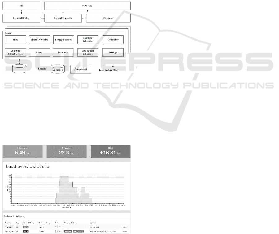
A frontend visualizes the system state for each
customer and provides the means to control all
integrated components. A screenshot of the actual
frontend of the EMS prototype is depicted in figure
3 showing the real-time load at a charging site, the
current energy production and an overview of the
vehicle states.
Figure 3: Frontend visualization showing the load and
production parameters and the state of the cars for the
customer.
As depicted in Figure 2, each tenant possesses a
set of the master data of all components in their
system. Furthermore, each tenant possesses a
controller which has timed tasks that run multiple
times a minute to read out the value of the pre-
calculated charging profiles from the charging
schedule and set the power-output set-point to the
charging station while minimizing the error between
production and consumption.
Here, the association between charging station
and physically connected vehicle is important. The
identification of the car which is connected to the
charging station can be done in several ways. Each
user is assigned a user-specific token. A token is an
identification number which uniquely identifies each
user in the system. In this way, the EV can be
identified by looking up the vehicle which was used
by the user who checked in to the charging station.
During this procedure, the token can either be
transmitted via a smartphone application or be read
from a RFID-card in the charging station.
Unfortunately, current EVs do not transmit any
unique identification to the charging station. Hence,
in the SEF project, we used a user identification
which is transmitted to the charging station for
authentication with the system via a smartphone
application.
During charging, the controller continuously
measures the power drawn from the connected EV
and compares it to the pre-calculated profile. Any
occurring deviation is reduced according to the
individually selected strategy. This ensures that grid
limitations and optimization goals are met.
During each charging session of the EV the
smart meter values of the charging stations are
sampled in a 15 minute interval. Using this data, the
consumption module computes time dependent
energy costs of each session. This enables the fleet
operators to use dynamical energy plans of their
DSO.
A charging schedule holds the charging profile
for each EV in the system. It is calculated based on
the EV disposition schedule. As soon as the
disposition schedule is updated by any entity, the
charging schedule is updated subsequently. For
planning the charging schedule, it is assumed that a
vehicle is connected to the charging station as soon
as it returns from its trip. Connecting the vehicle is
mandatory for each user. In case of a missing, but
expected connection, the user is notified. As a
consequence, the time between the end of a
proceeding and the start of an upcoming trip is
considered available for charging. Only if a user
explicitly wishes to charge in the meantime, during
SMARTGREENS 2016 - 5th International Conference on Smart Cities and Green ICT Systems
344

an ongoing booking, this request is taken into
account in the charging optimization. The charging
optimization is performed by the optimizer. Based
on the selected charging strategy, the optimizer
schedules and performs an optimization calculation
which is described in detail in the next section.
Through this architecture a multi-tenant, flexible and
scalable EMS aggregator is realized connecting
multiple sites respectively integrating multiple self-
sufficient micro grid into one control unit.
5 CHARGING PROFILE
OPTIMIZATION
The central component of the EMS is the
optimization module. Controlling the charging
processes of a fleet of EVs requires the system to
continuously update the charging schedule based on
the current system state. Two distinctive events
trigger the optimization of the charging plan. Since
the EMS does not plan the disposition of the fleet, it
has to react to changes of the disposition schedule.
Hence, an event is sent by the disposition optimizer,
notifying the EMS about the updated or changed
disposition schedule. Even without disposition
changes, the charging schedule is periodically
updated in constant intervals by the EMS. Thus, it is
always able to react to the actual state of the system.
In this way, deviations of the expected SOC can be
taken into account. A task manager triggers an
optimization every 15 minutes if the schedule has
not changed in the preceding 5 minutes. On this
way, the optimization process has enough time to
perform a complete iteration before the next start is
triggered.
Especially for larger fleets, a fast optimization
process is mandatory, since the amount of vehicles
in the fleet have an impact on the computation time.
This can be reached for example by reducing the
complexity of the optimization problem to speed up
computation time. Different authors already found
out that linearization of the charging processes
respectively the battery behavior of EVs is sufficient
for coordinated smart charging. Nonlinear
approximation of the charging behavior does not
justify the increase in computation time (Sundstr.
2010; Hu et al., 2013). Because of that, we followed
the recommendation and chose linear programs (LP)
(Rardin, 1997) to perform optimized charging
profiles for EV charging. Thus, we picked a LP to
describe the constrains of the system at hand and
solve the objective function considering a
specifically selected charging strategy. For the
algorithm we discretized the time into timeslot
intervals of 15 minutes. Hence, a day of 24 hours
has 96 individual timeslots. We designed the
objective function of our LP in order to minimize
cost.
Based on the selected strategy the cost vector can
either be a time dependent energy price or the
amount of CO
2
emission produced by a certain
energy source when used for charging. Thus, an
economic or ecologic charging strategy can be
realized by adjusting the cost vector appropriately.
This way, the optimizer is capable of calculating the
optimal amount of power used at a designated
timeslot under consideration of the time dependent
cost of a specific energy source. Therefore, the
objective function of our LP looks as follows:
min
,,
;
;
; ;
(1)
Here, describes the index for the vehicle and
is
the maximum number of vehicles available to
optimize. Furthermore, describes the index of the
energy source and
the maximal number of energy
sources available to use. Each timeslot is denoted by
the index , whith
being the number of total
timeslots and by that the total timespan to be
optimized. Following, the parameter
,,
is defined
as
,,
,
∗
,,
∗0.25,
(2)
where parameter
,,
from equation 2 being
the cost of the energy charged into a EV v, using
energy source g at timeslot t. The parameter to be
optimized by the solver will be the output power
,,
. With the objective function given, the
following constrains are limiting the solution space.
First, the sum of the allocated power for charging all
vehicles using an energy source at timeslot t being
denoted as
,
must be lower or equal to the
forecasted amount of power for this respective
timeslot
,
:
,
,,
,…,
(3)
,
,
(4)
Vehicles can only be charged while connected to a
Energy-Management-as-a-Service: Mobility aware energy management for a shared electric vehicle fleet
345

charging station. Thus, by using a vector modelling
the connection of the EV to the charging stations,
the charged energy up to the trip k subsequent to a
charging session, can be defined to:
,
,
,
∗
,,
…
…
,
(5)
,
(6)
,
,
(7)
where
,
is the total amount of energy charged for
EV v,
,
the maximum amount energy which
can be charged into the battery of EV v.
Further,
,,
describes the parameter, denoting each
timeslot t in which the EV v is connected to a
charging station up to the beginning of trip k. The
parameter
,
describes the state of the connection
with
,
1 as connected and
,
0 as not
connected to the charging station. Equation 5
ensures that the sum of the energy charged up to the
start of trip k plus the initial SOC of the EV
,
has
to be at least the size of
, the amount of energy
required for trip k. Equation 7 ensures on the other
side, that the charged amount of energy does not
exceed the battery capacity of the respective EV. In
addition, assume
,
being the sum of the energy
charged at timeslot t:
,
,,
,…,
(8)
At any time, the amount of energy
,
drawn from
the charging station should neither exceed its
maximal power output capabilities nor the maximal
input power of the respective EV v, letting the
maximal power output be set to
,,
.
,
,,
(9)
Additionally, charging has always to be limited to
the times the EV is physically connected to the
charging station. From this follows:
,
,
∗
,
(10)
If the vehicle is not connected the parameter
,
at
this timeslot has to be zero.
If these constrains can be satisfied, the optimizer
calculates the best fitting charging profile for the
vehicles. Note, that the problem space of the
described LP scales linearly with the amount of
regarded EV, energy sources and days. Computation
time scales linearly with the size of the problem
space. Both can be reduced by either simplifying the
constrains to only focus on one single energy source
making the sum of all forecasts the maximum
available power or by reducing the amount of
regarded timeslots by decreasing computation range
or increasing slot duration.
In the Shared E-Fleet project, we focused on two
strategies for charging plan generation. We
differentiated between economic and ecologic
charging. Based on price forecasts only time
intervals will be considered for charging which are
ultimately required for charging the car to a specific
SOC necessary to perform a journey or which offer
considerably lower prices in comparison to another
time of day. With an ecologic strategy the algorithm
is supposed to charge the EVs mainly at times of the
day when renewable energy is generated.
Subsequently of the computation, the set points for
the maximum allowed output power is transformed
in a charging profile and stored as a charging
schedule. Based on the chosen strategy, different
charge profile schedules may emerge from the
calculations. After having stored the charging profile
for each vehicle, it is possible to calculate an
estimation for the SOC of each EV at a specific
point in time based on current system state. Thus, it
can be validated if the computed charging profiles
are able to perform all booked trips sufficiently.
6 PROTOTYPE AND
EVALUATION
Based on the proposed system architecture, we
developed a multi-tenant web application using Java
as a framework system. Hence, it was possible to
evaluate the previously introduced architecture and
algorithms as part of two model trials at two
charging site locations. As parts of this system we
integrated intelligent AC Level 2 charging stations at
each location with a capable maximum power output
of 22kW with our EMS. However, the here applied
EVs, four BMW i3, which were selected due to
overall project requirements, were only capable to
draw a maximum power of 4.6 kW. The vehicles
were equipped with specifically developed
telematics units, sending data to a real-time data
pool. This way, data is read out from the vehicles’
CAN-Bus. The collected data included among others
SMARTGREENS 2016 - 5th International Conference on Smart Cities and Green ICT Systems
346

the SOC, position, and estimated range. Data was
continuously sent to the data pool in five minute
intervals via a GSM module. The charging stations
were connected through a proprietary manufacturer
specific interface. This enabled the EMS to set the
maximum power output, as the acquired charging
stations were only supporting Open Charging Point
Protocol (OCPP) version 1.5 (Open Charge Alliance
2015). At the time of purchase, OCPP version 2.0
which supports power output set-point specification
had neither been finalized nor been implemented in
the hardware by any manufacturer.
Additionally, we monitored a PV power plant at
one of the locations continuously as a reference for
locally generated energy. Although it was not
physically connected to the charging stations due to
regulatory issues, the obtained data served as real
time data to model the behavior of a real PV plant.
In addition to the real time data of the PV plant, we
connected a production forecast system called
PVCast (Klein 2013). PVCast is a commercial
service, which predicts the generated power of a
given PV power plant, based on previously
measured data and increases its accuracy by new
measurements. Master data of charging stations,
vehicles and charging sites is provided by services
of the SEF system. As part of the SEF system, a
dynamic disposition management reschedules the
vehicles according to the vehicle SOC states. In the
prototype, the disposition management is connected
with the EMS and triggers it as soon as the schedule
is changed. With every trigger, it transmits the
complete disposition of the vehicles including the
start and end time of each trip, the distance and the
expected consumption.
With all services connected to the EMS, new
charging schedules are created as soon as the
disposition schedule changes. Unforeseen changes in
the states of the vehicles are mitigated by
periodically conducted optimizations taking into
account the holistic system state. Through that,
requirements R1 and R2 are fulfilled. Applying the
previously presented LP different charging strategies
are possible, fulfilling the requirement R3.
Furthermore, the integration of a building energy
management provides the EMS with data about the
connected electric power system components.
Therefore, R4 is fulfilled. Requirement R5 is
fulfilled by introducing a forecast system providing
the EMS with day-ahead energy production
information. Through the integration of a database,
storing the states of all integrated components and a
frontend, history data is always accessible fulfilling
R6. In the prototype, intelligent charging stations
were integrated and direct load control was possible.
By this, requirement R7 is fulfilled. The requirement
R8 is fulfilled by using a tenant manager in the
software architecture to support different MDM
clients. Furthermore, the tenant manager enables the
EMS to be dynamically scalable fulfilling R10.
However, the model trails could not be used to fully
evaluate all requirements. Due to real time operation
and its prototypic state, the system was not running
without interruption. Additional to that, not all EVs
were available at the same time because of
maintenance reasons. Because of that, a synthetic
scenario was created, using a fleet of 30 EVs This
scenario is similar to the situation at our institute
campus, if all vehicles with ICE were replaced with
BEV. Furthermore each of the EVs has its own
charging station. In this way, the vehicle will always
have the ability to charge . It is assumed that the EV
as well the charging stations are homogenous. For
the sake of the project context, the charging
characteristic of a BMW i3 was used to model the
charging behavior. That means that each vehicle has
a battery capacity of 18.8 kWh which is useable for
storing energy. The average power consumption of
the vehicles is assumed to be 12.3 kW per 100 km
distance. Making each car able to reach a total range
of approx. 147 km. Each vehicle can charge a
maximum power of up to 4.6 kW. That would
require the transformer to handle a maximum
concurrent peak power demand of 138 kW. To
simulate coordinated charging, the maximum usable
power is limited to 100 kW. Any additionally
required power can be provided by a physically
connected PV power plant at the charging site where
the charging stations are setup. For the evaluation,
the grid as well as the PV power plant serve as
energy source, supplying the charging station and by
this the connected EVs, to always provide energy
when needed. To present the results of the
optimization algorithm appropriately, three different
disposition schedules are applied to the fleet. Each
profile is applied to a third of the fleet. If EVs were
charged concurrently in this condition, they would
exceed the given local maximum power. The
consumption of each trip is assumed to be linear
according to the EV’s average consumption per
distance. The three profiles are listed in Table 1.
In this evaluation, optimizations regarding an
ecologic and an economic strategy are conducted.
Each result is compared with dumb charging. Dumb
charging means that the vehicles are charged directly
after plugging in the cable of the vehicles into the
charging station. The charging session is then
performed as long as the EV is connected and not
Energy-Management-as-a-Service: Mobility aware energy management for a shared electric vehicle fleet
347

Table 1: Applied disposition schedule profile types.
Profile
Number
Start
Time End Time
Distance
[km]
Consumption
[kW]
1
05:30:00 14:10:00 65 8,00
17:30:00 18:30:00 85 10,46
21:00:00 23:30:00 45 5,54
2
07:30:00 11:30:00 75 9,23
14:45:00 16:00:00 30 3,69
18:00:00 22:30:00 100 12,30
3
05:30:00 09:30:00 55 6,77
15:00:00 18:30:00 30 3,69
fully charged. If not directly controlled by the
charging station itself, concurrent charging of the
vehicles would lead to stress on the transformer at
the site which might even lead to an overload or
fatal hardware failure. An production forecast is
created using a forecast given by PVCast with an
adjusted peak power of 40 kW. Additionally, an off-
peak tariff is assumed. In the peak time, between 6
am and 8 pm, the energy costs 11 cent/kWh,
whereas in the off-peak time at the rest of the day,
energy costs 7 cent/kWh. The cost of using solar
energy is set to be 9 cent/kWh for the whole
regarded time period and hence being cheaper than
the energy from the grid in the peak time period.
Each optimization is performed considering a time
span of 24 hours, resulting in a total time span of 96
timeslots. Each vehicle is supposed to be completely
empty at the start of the day. As a solver, the solver
of the free Apache Commons Library (The Apache
Software Foundation 2016) was used. The result of
the economic strategy is depicted in Figure 4.
Figure 4: Comparison of optimization results of economic
charging strategy and dumb charging.
Figure 4 compares dumb charging with economic
charging. In the applied scenario, the concurrent
charging is limited by the local load constrain to the
maximum power limitation of 100 kW. Only as
much energy is charged as is required to conduct the
trips. All charging operation is only performed
during the morning hours of the day, due to the low
energy costs. With dumb charging, the fleet would
be charged two additional times during the day.
With a smart charging strategy, this is not necessary.
Since in case of the economic and the ecologic
strategy, only the trip demand is charged, 64% of the
energy can be saved compared to dumb charging
and thus being more energy efficient. Regarding the
energy cost, in the economic scenario, 30% of the
energy cost could be saved. In Figure 5, the results
of optimization with the ecologic optimization
strategy are depicted.
Figure 5: Comparison of optimization results of ecologic
charging strategy and dumb charging.
In Figure 5, it can be observed, that charging in the
morning is deferred and continued in the afternoon,
when solar energy is available. Thus, CO
2
emission
is mitigated by using renewable energy instead of
energy from the grid. With the ecologic strategy, it’s
possible to save even 76% of CO
2
emission by not
immediately start charging the EVs and by deferring
the charging sessions into times of renewable energy
production. This synthetic evaluation shows, that
local grid constrains are not exceeded, and thus
requirement R9 is always fulfilled. Furthermore,
requirement R5 is satisfied by taking into account
the production forecast of the PV power plant with
the ecologic evaluation.
By fulfilling all requirements, a fully functional
framework is created, serving as EMS and being
able to perform smart charging as part of an
intelligent energy management service.
7 CONCLUSION AND OUTLOOK
In this work, we introduced the architecture of a
cloud-based EMS, serving as a scalable and flexible
SMARTGREENS 2016 - 5th International Conference on Smart Cities and Green ICT Systems
348

system to monitor and control the charging of a fleet
of EVs. It enables fleet operators to integrate their
energy components and a fleet of EV into an EMS,
providing them with the means to systematically
improve the usage of these components. For this, we
included an optimizer to calculate charging profiles
for an EV fleet, in order to exploit energy production
forecasts and dynamic price tariffs. The evaluation
showed that optimization of the charging profile
delivered charging profiles which sufficiently served
the mobility demands of the user, kept the
boundaries of the energy system and minimize costs.
By this, the here presented aggregator can
accomplish primary objectives of energy
management systems like increasing energy
efficiency, reduction of the energy used for charging
and maximization of profits by minimization of
costs. (Barney et al. 2008)
In the future, we plan to extent this approach to
completely control different micro grids in islanded
mode operation resulting in a smart micro grid. By
providing this framework for a cloud-based and
flexible EMS, we plan to integrate more energy
components, further investigating cloud-based
hierarchical control. Thus, enabling the combination
of free floating EV fleets with multiple micro grid
controls to provide ancillary services and to
maximize profits and simultaneously stabilizing the
grid. As a consequence, we will conduct further
research to decrease runtime of optimization
processes in order to tackle a growing amount of
optimization parameters. Especially interesting is the
coordination of EMS optimization and disposition
planning considering different charging sites and
energy-aware routing of vehicles.
ACKNOWLEDGEMENTS
This research has been supported by the IKT II
program in the Shared E-Fleet project. They are
funded by the German Federal Ministry of
Economics and Technology under the grant number
01ME12105. The responsibility for this publication
lies with the authors.
REFERENCES
Alonso, M., Amaris, H., Germain, J. G., and Galan, J. M.,
2014. Optimal charging scheduling of electric vehicles
in smart grids by heuristic algorithms. Energies, 7 (4),
2449–2475.
Barney, L. C., Wayne, C. T., and William, J. K., 2008.
Guide to Energy Management. Lilburn, GA 30047,
US: 6th Edition, 1.
Barth, M., Todd, M., and Murakami, H., 2000. Intelligent
Transportation System Technology in a Shared
Electric Vehicle Program. Transportation Research
Record, (1731), 88–95.
Buyya, R., Yeo, C. S., Venugopal, S., Broberg, J., and
Brandic, I., 2009. Cloud computing and emerging IT
platforms: Vision, hype, and reality for delivering
computing as the 5th utility. Future Generation
Computer Systems [online], 25 (6), 599–616.
Available from: http://portal.acm.org/citation.cfm?
id=1528937.1529211.
Chu, S. and Majumdar, A., 2012. Opportunities and
challenges for a sustainable energy future. Nature
[online], 488 (7411), 294–303. Available from:
http://www.nature.com/doifinder/10.1038/nature11475.
Chynoweth, J., Chung, C. Y., Qiu, C., Chu, P., and Gadh,
R., 2014. Smart electric vehicle charging infrastructure
overview. 2014 IEEE PES Innovative Smart Grid
Technologies Conference, ISGT 2014.
Clement-Nyns, K., 2010. The impact of charging plug-in
hybrid electric vehicles on a residential distribution
grid. Power Systems, IEEE… [online], 25 (1), 371–
380. Available from: http://ieeexplore.ieee.org/xpls/
abs_all.jsp?arnumber=5356176.
Deilami, S., Masoum, A. S., Moses, P. S., and Masoum,
M. a S., 2011. Real-time coordination of plug-in
electric vehicle charging in smart grids to minimize
power losses and improve voltage profile. IEEE
Transactions on Smart Grid, 2 (3), 456–467.
Delucchi, M. A. and Lipman, T. E., 2001. An analysis of
the retail and lifecycle cost of battery-powered electric
vehicles. Transportation Research Part D: Transport
and Environment.
García-Villalobos, J., Zamora, I., San Martín, J. I.,
Asensio, F. J., and Aperribay, V., 2014. Plug-in
electric vehicles in electric distribution networks: A
review of smart charging approaches. Renewable and
Sustainable Energy Reviews [online], 38, 717–731.
Available from: http://dx.doi.org/10.1016/j.rser.
2014.07.040.
German Federal Government, 2009. National
Electromobility Development Plan [online]. Available
from: http://www.bmwi.de/Dateien/BMWi/PDF/
nationaler-entwicklungsplan-elektromobilitaet-der-
bundesregierung,property=pdf,bereich=bmwi,sprache
=de,rwb=true.pdf [Accessed 26 Oct 2015].
Han, S., Han, S., and Sezaki, K., 2010. Development of an
optimal vehicle-to-grid aggregator for frequency
regulation. IEEE Transactions on Smart Grid, 1 (1),
65–72.
Hu, J., You, S., Si, C., Lind, M., and Østergaard, J., 2013.
Optimization and control method for smart charging of
EVs facilitated by Fleet operator. Review and
classification, 10 (1), 383–397.
Hu, J., You, S., Si, C., Lind, M., and Østergaard, J., 2014.
Optimization and Control Methods for Smart
Charging of Electric Vehicles Facilitated by Fleet
Operator: Review and Classification. International
Energy-Management-as-a-Service: Mobility aware energy management for a shared electric vehicle fleet
349

Journal of Distributed Energy Resources and Smart
Grids, 10 (1), 383–397.
Jansen, B., Binding, C., Sundström, O., and Gantenbein,
D., 2010. Architecture and Communication of an
Electric Vehicle Virtual Power Plant. Smart Grid
Communications (SmartGridComm), 2010 First IEEE
International Conference on, 149–154.
Klein, M., 2013. PVCast- Simple and flexible energy yield
forecasts for photovoltaic plants. [online]. Available
from: http://www.pvcast.de.
Koetter, F., 2015. Dynamische Einsatzoptimierung von
gemeinsam genutzten Elektrofahrzeugfotten [online].
Available from: http://www.shared-e-fleet.de
images/Dynamische_Einsatzoptimierung_von_gemein
sam_genutzten_Elektrofahrzeugflotten.pdf [Accessed
2 Jun 2015].
Lee, D. A., Cook, G., Ford, N. P., Freeland, R. L., Gilliam,
F. M., Hough, J. A., Bridge, G. G., and Scott, B. A.,
2005. Car-Sharing: Where and How It Succeeds.
Transit Cooperative Research Program Report 108.
Lopes, J. a P., Soares, F. J., and Almeida, P. M. R., 2010.
Integration of Electric Vehicles in the Electric Power
System. Proceedings of the IEEE, 99 (1).
Lutzenberger, M., Kuster, T., and Albayrak, S., 2014.
Integrating electric vehicles into smart grid
infrastructures a simulation-based approach that
became reality. In: Proceedings of the Winter
Simulation Conference 2014 [online]. IEEE, 1061–
1072. Available from: http://ieeexplore.ieee.org/
lpdocs/epic03/wrapper.htm?arnumber=7019965.
Mukherjee, J. C. and Gupta, A., 2014. A Review of
Charge Scheduling of Electric Vehicles in Smart Grid.
IEEE Systems Journal [online], 1–13. Available from:
http://ieeexplore.ieee.org/lpdocs/epic03/wrapper.htm?
arnumber=6919255.
Mültin, M., Allerding, F., and Schmeck, H., 2012.
Integration of electric vehicles in smart homes - An
ICT-based solution for V2G scenarios. 2012 IEEE
PES Innovative Smart Grid Technologies, ISGT 2012.
Open Charge Alliance, 2015. OCPP – Open Charge Point
Protocol [online]. Available from: http://www.ocpp.nl
[Accessed 9 Nov 2015].
Ostermann, J., Koetter, F., Renner, T., and Hudert, S.,
2014. Leveraging Electric Cross-Company Car Fleets
through Cloud Service Chains: The Shared E-Fleet
Architecture. In: 2014 Annual SRII Global Conference
[online]. San Jose, CA: IEEE, 290–297. Available
from: http://ieeexplore.ieee.org/lpdocs/epic03/wrapper
.htm?arnumber=6879697.
Plötz, P., Gnann, T., Kühn, A., and Wietschel, M., 2014.
Markthochlaufszenarien für Elektrofahrzeuge.
Fraunhofer ISI, 2013 (September 2013).
Raab, A. F., Ferdowsi, M., Karfopoulos, E., Unda, I. G.,
Skarvelis-Kazakos, S., Papadopoulos, P., Abbasi, E.,
Cipcigan, L. M., Jenkins, N., Hatziargyriou, N., and
Strunz, K., 2011. Virtual Power Plant Control
concepts with Electric Vehicles. 16th International
Conference on Intelligent System Applications to
Power Systems [online], 1–6. Available from:
http://ieeexplore.ieee.org/lpdocs/epic03/wrapper.htm ?
arnumber=6082214.
Rardin, R. L., 1997. Optimization in Operations Research.
New Jersey, US: Prentice Hall (Higher Education
Division, Pearson Education), 131–174.
Saker, N., Petit, M., and Vannier, J. C., 2011. Electric
vehicles charging scenarios associated to Direct Load
Control programs (DLC). NAPS 2011 - 43rd North
American Power Symposium, (Dlc).
Sundstr, O., 2010. Optimization Methods to Plan the
Charging of Electric Vehicle Fleets. Proceedings of
the International Conference on Control
Communication and Power Engineering [online], 28–
29. Available from: http://www.zurich.ibm.com/
pdf/csc/EDISON_ccpe_main.pdf.
Sundström, O. and Binding, C., 2012. Flexible charging
optimization for electric vehicles considering
distribution grid constraints. IEEE Transactions on
Smart Grid, 3 (1), 26–37.
The Apache Software Foundation, 2016. Commons Math:
The Apache Commons Mathematics Library [online].
Available from: http://commons.apache.org/proper/
commons-math/ [Accessed 11 Feb 2016].
Valogianni, K., Ketter, W., Collins, J., and Zhdanov, D.,
2014. Effective Management of Electric Vehicle
Storage using Smart Charging.
Vandoorn, T. L., Zwaenepoel, B., Kooning, J. D. M. De,
Meersman, B., and Vandevelde, L., 2011. Smart
microgrids and virtual power plants in a hierarchical
control structure. 2nd IEEE PES International
Conference and Exhibition on Innovative Smart Grid
Technologies [online], 1–7. Available from:
http://ieeexplore.ieee.org/lpdocs/epic03/wrapper.htm?
arnumber=6162830.
Zuccaro, L., Di Giorgio, A., Liberati, F., Canale, S.,
Lanna, A., Pallares, V. F., Blanco, A. M., Escobar, R.
U., Ratej, J., Mehle, B., and Krisper, U., 2014. Smart
vehicle to grid interface project: Electromobility
management system architecture and field test results.
In: 2014 IEEE International Electric Vehicle
Conference (IEVC) [online]. 1–7. Available from:
http://arxiv.org/ftp/arxiv/papers/1503/1503.01266.pdf.
SMARTGREENS 2016 - 5th International Conference on Smart Cities and Green ICT Systems
350
