
Light Field Rendering for Head Mounted Displays using Pixel
Reprojection
Anne Juhler Hansen, J
´
akup Klein and Martin Kraus
Department of Architecture, Design & Media Technology, Aalborg University, Rendsburggade 14, 9000 Aalborg, Denmark
Keywords:
Light Field, Pixel Reprojection, Shader Programming, Real-time Rendering.
Abstract:
Light field displays have advantages over traditional stereoscopic head mounted displays, for example, because
they can overcome the vergence-accommodation conflict. However, rendering light fields can be a heavy task
for computers due to the number of images that have to be rendered. Since much of the information of the
different images is redundant, we use pixel reprojection from the corner cameras to compute the remaining
images in the light field. We compare the reprojected images with directly rendered images in a user test. In
most cases, the users were unable to distinguish the images. In extreme cases, the reprojection approach is not
capable of creating the light field. We conclude that pixel reprojection is a feasible method for rendering light
fields as far as quality of perspective and diffuse shading is concerned, but render time needs to be reduced to
make the method practical.
1 INTRODUCTION
Development of head mounted displays (HMDs) has
evolved significantly during the last years, especially
considering the consumer markets and consumers’
use of HMDs, e.g., Oculus Rift, HTC Vive, Sony
PlayStation VR, etc. One of the shortcomings and
challenges of traditional HMDs is the lack of 3-
dimensional cues, hereunder the parallax effect for
small eye movement and correct eye accommoda-
tion. The vergence-accommodation conflict has been
under suspicion of causing visual fatigue, eyestrain,
diplopic vision, headaches, and other signs of simula-
tion sickness (Hoffman et al., 2008).
In the future, it might be possible to eliminate vi-
sual discomfort and nausea since a light field display
can provide correct retinal blur, parallax and eye ac-
commodation, which may balance out some of the
conflicting cues which are experienced with tradi-
tional HMDs. A light field display allows an observer
to perceive a scene at different depths and angles by
placing a distance-adjusted array of microlenses in
front of a display.
When rendering for a light field display with mi-
crolenslets, several 2D subimages have to be rendered
from different views, as seen from an array of differ-
ent cameras. We hypothesize that we can compute all
views from only four rendered cameras using pixel
reprojection instead of rendering the whole array of
virtual cameras. This paper investigates the feasibil-
ity of this approach to create light field renderings,
and explores its benefits and shortcomings.
A head-mounted light field display has been built
and implemented, and a user evaluation of the light
field images has been conducted. The goal of the ex-
periment is to find out if users are able to perceive a
difference in the light field images created with the
two different methods; rendering of the full array of
cameras and pixel reprojection from images of only
four cameras.
Our contributions are:
• We propose a method to render light fields using
pixel reprojection that reduces the number of vir-
tual cameras.
• We evaluated whether or not test subjects are able
to notice a difference in the image quality with the
use of a two-interval forced choice test.
2 RELATED WORK
2.1 Vergence-Accommodation Conflict
Vergence and accommodation are parameters that in-
fluence our perception of depth and focus. In real-
ity, the human ocular system will adapt when focus
Juhler Hansen A., Klein J. and Kraus M.
Light Field Rendering for Head Mounted Displays using Pixel Reprojection.
DOI: 10.5220/0006091100270036
In Proceedings of the 12th International Joint Conference on Computer Vision, Imaging and Computer Graphics Theory and Applications (VISIGRAPP 2017), pages 27-36
ISBN: 978-989-758-224-0
Copyright
c
2017 by SCITEPRESS – Science and Technology Publications, Lda. All rights reserved
27

is changed between different distances, such that the
point of interest remains binocularly fused.
Accommodation refers to the physical shape of
the lens of the eye, where the eye adapts optical power
to maintain a clear focused image. The vergence
mechanism continually adjusts the angle between the
two eyes such that features at the focus distance re-
main fused in the binocular vision.
A change in visual cues will affect both system;
stereo disparity drives the eyes to converge or di-
verge, and retinal blur prompts an oculomotor ac-
commodation adjustment. To further strengthening
the argument of these systems being very tightly cou-
pled, Suryakumar et al. have shown that visual dis-
parity in isolation elicits a fully comparable accom-
modation response to that of retinal blur (Suryakumar
et al., 2007). However, in traditional stereo imaging
where the depth is fixed, vergence towards a differ-
ent distance elicits conflicting cues between the two
systems; this has been linked to discomfort (Shibata
et al., 2011), visual fatigue, and reduced visual per-
formance (Hoffman et al., 2008).
One of the consequent benefits of a light field dis-
play is that it allows natural accommodation and ver-
gence. Focusing at different distances simply deter-
mines which parts of the 2D image slices are focused
onto the retina.
2.2 The Light Field
A light field can be described as the amount of light
travelling in every direction through every point in
space (Levoy, 2006). Light can be interpreted as a
field because space is filled with an array of light rays
at various intensities. The 5D plenoptic function de-
scribes all light information visible from all viewing
positions, and can be explained as recording the in-
tensity of the light rays passing through the center of
a pupil placed at every possible x, y, and z in a 3-
dimensional volume, and at every angle θ and φ.
Since radiance does not change along a line un-
less it is blocked, the 5D plenoptic function can be
reduced to 4D in space free of occluders (Levoy and
Hanrahan, 1996). The 4D light field can explain the
total light intensity of each ray as a function of posi-
tion and direction.
2.3 Head-Mounted Light Field Displays
Head-Mounted Displays (HMDs) are still struggling
with being heavy and having big and bulky optics,
and most traditional HMDs do not account for the
vergence-accommodation conflict (Rolland and Hua,
2005). Since light fields consist of more informa-
tion than usual 2D images, light fields can improve
on some of the limitations of traditional fixed-focus
HMDs.
A light field can be optically reconstructed by
placing a distance-adjusted array of microlenses in
front of a display (see Figure 1). This is known as
a light field display. A light field display allows an
observer to integrate a correct 2D image of the light
field at different depths and angles in accordance with
the spatial and depth resolution that the light field con-
tains. In other words, the light field display allows an
observer to accommodate and converge his/her eyes
on a virtual object as if it were part of the real world.
The image seen through a light field display has focus
cues, where the convergence point is the point in fo-
cus, and the rest of the image appears blurred just like
in the real world.
With the benefits from using microlenslet arrays in
HMDs, Lanman and Luebke have shown that a light
field display can be integrated into an HMD, which
can both minimize the size of HMDs and potentially
allow for much more immersive VR solutions com-
pared to the fixed focus displays used in most com-
mon HMDs (Lanman and Luebke, 2013).
2.4 Light Field Rendering
One of the first times light fields were introduced
into computer graphics was by Levoy et al. in 1996,
where they used image based rendering to compute
new views of a scene from pre-existing views without
the need for scene geometry (Levoy and Hanrahan,
1996). The technique showed a real-time view of the
light field, where it was possible to see a scene with
correct perspective and shading, and with the option
of zooming in and out. When zooming in, the light
samples disperse throughout the array of 2D slices, so
the perceived image is constructed from pieces from
several elemental images.
Reducing complexity is highly desired when
working with light fields, and (re)construction of
overlapping views is a good place to start, since this
is where the light field contains a lot of redundant in-
formation. Much of the data is repetitive, especially
when looking at a scene placed at infinity, where all
subimages are created from parallel light rays. Instead
of creating a virtual camera or capturing an individual
subimage for each elemental image, we hypothesize
that pixel reprojection can be used to reduce the com-
putational effort.
GRAPP 2017 - International Conference on Computer Graphics Theory and Applications
28

Figure 1: An observer sees the light field by looking through a microlens array in front of a screen, where each lens covers
one subimage. Rays from different subimages enter the pupil of the observer, and the light field is experienced as one image,
where the light samples disperse throughout the array of subimages. When focus (vergence and accommodation) is changed,
the perceived image will be constructed from rays from other subimages.
2.5 Pixel Reprojection
Pixel reprojection is about reprojecting data (e.g.
color values) from one image to another. Geomet-
rically valid pixel reprojection techniques have been
studied by Kang, who stated that “if the depth value
at each pixel is known, then the change in location of
that pixel is constrained in a predictable way” (Kang,
1998). The traditional approach for generating virtual
views of a scene is to render a 3D model, but with
image-based rendering techniques new views can be
created using pixel reprojection from source images
onto the target image, and thereby the method does
not need to process the geometry of the 3D models,
and the cost of rendering is independent of the scene
complexity.
Pixel reprojection can be used when rendering
video, where data reprojection can exploit the natu-
ral temporal coherence between consecutive frames
by caching expensive intermediate shading calcula-
tions performed at each frame, and then reuse this
data when rendering subsequent frames (Sitthi-amorn
et al., 2008). Pixel reprojection can therefore also be
used as a tool to optimize shaders since reusing data
between consecutive frames can accelerate real-time
shading (Nehab et al., 2007)(Havran et al., 2003). In
general, pixel reprojection is a useful technique in
the field of computer graphics (Adelson and Hodges,
1995)(Tawara et al., 2004).
3 IMPLEMENTATION AND
METHODS
Our approach is to render only the four corner cam-
eras of the subimage array, and then use these four
views in order to create all subimages of the light
field. We implement all the computations of the
subimages of the light field with the use of pixel
reprojection, while maintaining correct perspective
and diffuse shading, and investigated where short-
comings of the pixel reprojection occured. The light
field display was implemented with microlenslets in a
setup that was inspired by Lanman and Luebke 2013.
3.1 Rendering the Light Field
Using the Unity engine, we render a virtual image for
every lenslet that is within the bounds of the microdis-
play, so the light field will be perceived as one holo-
graphic image with focus cues. Each subimage (or
elemental image) is rendered to a portion of the mi-
crodisplay; optimally 15mm × 8mm out of 15.36mm
× 8.64mm to utilise as much of the spatial resolution
as possible.
Since the perceived image is constructed from
pieces from several subimages, we need to render all
these subimages in an array corresponding to the di-
mensions of our microlens array. The secure and reli-
able solution would be to render 15 × 8 different vir-
tual cameras, where each camera has the same align-
ment as the lenslets. We refer to this as a light field
Light Field Rendering for Head Mounted Displays using Pixel Reprojection
29

image created with virtual cameras. We consider this
the gold standard and compare our approach to this
method in tests. As previously mentioned, our ap-
proach is to render only the four corner cameras of
the subimage array, and then use pixel reprojection to
create the subimages in-between the four corner cam-
eras.
Our method can be outlined by five steps:
1. First we render the four corner cameras to sep-
arate render textures. The depth is saved in the
alpha channel.
2. Then a shader calculates the in-between images
on the x-axis on the top and bottom row.
3. The x-axis result is saved to a render texture, and
from that another shader calculates the in-between
images on the y-axis.
4. Again the result is saved to a render texture, and
anti-aliasing is done using downsampling in a
third shader.
5. Lastly, the image is scaled to fit the display output
by a fourth shader.
3.2 Pixel Reprojection
The subimages are computed by pixel reprojection,
where the pixels from the corner images are copied to
the corresponding place in each subimage. To achieve
this, the pixel must be placed back to the 3D world
and be “captured” to the computed subimage. Here
the view space must be projected to the image plane
that will be displayed on the screen. The input pixel
energy must be redistributed to the output pixel based
on the exact overlap between these pixels.
The transformation goes back and forward be-
tween the projection plane (the generated 2D image)
and the eye/camera space (the 3D scene with the cam-
era as the center) (see Figure 2). All in-between views
have an individual position in world space and need to
do a transformation between these spaces in order to
generate the subimages. If the projection plane for
one camera and the transformation in relation to the
other camera is known, then the pixels can be repro-
jected to the other camera. Finally the view space is
projected onto the 2D screen.
Our transformation depends on the x-coordinates
on both the projection plane, x
p
, and in eye space, x
e
,
as well as the depth of the projection plane n and the
z-position z
e
in eye space (see Equation 1).
x
p
x
e
=
−n
z
e
(1)
The x-coordinate in eye space, x
e
, is mapped to
x
p
, which is calculated by using the ratio of similar
triangles.
We need the depth information of the scene to ef-
fectively interpolate between the images. Using per-
spective projection the relation between z
e
and the
value that is stored in the depth buffer, z
n
, is non-
linear with high precision at the near plane and little
precision at the far plane.
The transformation from the projection plane to
the eye space requires the depth from the eye space.
The depth is saved from the corner cameras into the
(unused) alpha channel. It was found through experi-
mentation that a 32 bit per channel texture was suffi-
cient to give accurate depth information.
Accurate depth is crucial for the pixel reprojec-
tion method to work. This also means that no anti-
aliasing can be performed on the four corner cam-
eras due to the fact that while the smoother edges of a
anti-aliased image are more esthetically pleasing, they
would no longer match the depth map, resulting in ar-
tifacts in the reprojected images. Anti-aliasing can
still be achieved by downsampling after all pixel re-
projection calculations are finished.
3.3 Filling the Gaps
There are cases where pixel reprojection does not
yield a full image, but rather an image with gaps. This
is because in some cases objects will occlude other
objects in such a way that when the camera is being
reprojected, information is missing. The effect can
be seen when a computed image is comprised of the
pixels from two corner cameras, but because of the
way the objects are placed in the scene, there are spots
where the depth and colour are unknown. The size of
the invisible “shadow” depends on the distance from
the camera to the occluding object and the distance
between the camera that captures the scene and the
pixel reprojected camera.
The problem is that the required information is not
available. One easy solution would be to include more
cameras to the scene (e.g. 5 cameras — one in the
center and one in each of the four corners — would
eliminate many cases). When the information is not
available then the holes must be filled with something
that hides them as well as possible. One could use
the pixels on the edge of the hole and use them to
fill in the hole. This could however lead to visible
pixel “streaks”. Another solution is to use an average
colour of the available information. In this project the
missing pixel values were filled by using the subpixel
position where the pixel value from the corner images
were read, and then using the mean of these values,
the pixel value could be created. The result is that
the holes are filled with colours that are present in the
GRAPP 2017 - International Conference on Computer Graphics Theory and Applications
30

(x
e2
,y
e2
,z
e2
)
(x
pB
,y
pB
)
(x
pA
,y
pA
)
(0
pB
,0
pB
)
CamB
(0
eB
,0
eB
,0
eB
)
CamA
(0
eA
,0
eA
,0
eA
)
(0
pA
,0
pA
)
Projection
plane length
(x
pB
,y
pB
)
(x
e1
,y
e1
,z
e1
)
(x
pA
,y
pA
)
Figure 2: Pixel reprojection shown betwen two cameras (CamA and CamB). A pixel can be reprojected from a corner camera
(CamA), to a pixel reprojected camera (e.g. CamB). The cameras have coordinates in the 3-dimensional eye space, whereas
the projection plane is 2-dimensional.
scene and there are no pixel “streaks”.
3.4 Shader Programming
The pixel reprojection requires a number of calcula-
tions to be made for every pixel. Because of the large
amount of calculations and the repeatability of the
calculations, a shader would be a good tool. In this
case a Cg shader was used in the Unity engine.
There are disadvantages of using a shader for the
pixel reprojections. It would be easy to reproject a
pixel with known depth and color from a pre-rendered
camera to a reprojected camera. It is not as simple to
find the correct reprojected pixel position in a subim-
age from the pre-rendered camera since the depth is
unknown from the reprojected camera.
Our method starts with a fragment shader that runs
in a loop over all possible pixels in the subimages
from the pre-rendered cameras. We then run a loop to
choose the best pixel match based on the pixel with
closest depth to the reprojected camera. All pixel
values in the reprojected camera start with an output
value of [0.0,0.0,0.0,2.0]. If the depth is smaller than
2.0 (which it will always be the first time), then the
color for the actual fragment pixel position is chosen
from the camera with the lowest pixel depth.
If the scene being captured by the pre-rendered
cameras is placed at infinity, then all subimages show
the same image. In this case any position on any re-
projected subimage should be filled with the colour
from a pre-rendered corner camera at the same posi-
tion. If, however, the scene contains elements placed
closer than infinity to the pre-rendered cameras, then
there is a difference between the position of those pix-
els on the projection plane of the pre-rendered camera
and the pixels on the projection plane of the repro-
jected camera.
This distance is greatest at the near clipping plane
and zero at infinity (see Equation 1), where x
e
is
changed in order to offset it to a new camera position,
the position x
p
would depend on the depth z
e
.
Knowing this and the two subimages’ positions
relative to each other, one only needs to check all pos-
sibilities. Given any reprojected pixel position, the
same position is checked in the pre-rendered camera
subimages, and then the neighbours are checked until
the maximum disparity is reached.
The variables that affect maximum disparity are
the distance to the closest object (or rather the cam-
eras’ near clipping plane), the distance between the
pre-rendered corner camera and the point where the
pixel reprojected camera is placed, and the cameras’
field of view. None of the reprojected pixels are nec-
essarily a perfect match, but one of them should be
the closest and within 0.5 pixels. This is the maxi-
mum distance from the center of the pixel to the edge
of the pixel (if the match would be more than 0.5 off
then the best pixel match has not been found).
It is important to note that the disparity is not one-
dimensional but two-dimensional since all cameras lie
on a two dimensional plane. Here the x- and y-axis
can be calculated separately. If a “two step” approach
Light Field Rendering for Head Mounted Displays using Pixel Reprojection
31

is used, then one axis is calculated first and saved to
a texture. After this step the other axis is calculated,
but it is worth mentioning that saving the render tex-
ture one time more than necessary implies extra com-
putation time. If a “one step” approach is used, then
the number of times that values have to be written to
textures is reduced. However, one needs to consider
the added calculation (and logic) necessary to find the
correct pixel in one step. The two step approach was
used in this project due to debugging purposes where
errors were easily located because the different stages
of the program could be inspected separately.
A sub-pixel correction is needed since the subim-
ages are a result of (up to) all four corner cameras.
One pixel from one of the corner cameras will be the
best match for any given subimage pixel, but this pre-
rendered subimage pixel will not necessarily match
up to the reprojected pixel being calculated. The off-
set is slightly different for each pre-rendered camera
due to their different corner positions. The closest
pixel match is up to 0.5 pixel off, and the offset can
be calculated, resulting in a position that is between
pixels in the pre-rendered subimage. Linear interpo-
lation is used on these pixels giving a color value for
the reprojected subimage pixel. In our setup this point
can be between two pixels (either on the x-axis or on
the y-axis).
The pixel values lend themselves quite well to in-
terpolation, but this is not the case with the depth map.
The depth map can easily be interpolated on surfaces.
The edges of objects are, however, being smudged if
the difference of the neighboring pixel depths is large.
An example would be a scene with an object rel-
atively far from infinity. This would result in three
neighbouring pixels where one has the depth of the
background, one has the depth of an object, and the
middle pixel has a depth that is somewhere in be-
tween. The simple solution is not to interpolate the
depth while interpolating the colour values. This re-
sults in an image where the pixel values and depth
values do not match completely but are quite close
to correct. The downside is that the pixel values are
interpolated while the depth is not, meaning that the
edge of an object can go beyond the edge in the depth
map, effectively spilling colour to the neighbouring
objects.
The computation of the pixel reprojection was
split into five steps (see Section 3.1). The first step
saves the depth to the alpha channel, and secondly
the reprojected subimages on the x-axis between the
pre-rendered corner images are computed (see Fig-
ure 3). The result was an image where the top and
bottom row were filled with reprojected subimages.
The rest of the image was filled with the mean of the
colour values from the corner cameras since the mean
value is a better guess for the pixel colors compared
to missing the information completely. The next step
computed the values from the two rows of subimages
and thus filled the remainder of the image with repro-
jected subimages in the y-axis. Because the x-axis
and y-axis is computed in two steps special care had
to be taken to avoid looking beyond the boundaries
of the reprojected images. First we check that the
position is within the image, after this step the sub
pixel correction is performed. This process utilises
linear interpolation of two pixels, and if this interpo-
lation is performed sufficiently close to the edge of
the image, then the pixel that resides in the image
is interpolated with a pixel that is outside the image
boundary. The problem was solved by clamping all
textures. Clamping means that the edge pixels will
be repeated beyond the boundaries of the image. The
complete image was rendered in four times the resolu-
tion of the screen, and then downsampled to achieve
anti-aliasing. The last step after downsampling was
scaling. The reason for this step is that the previous
steps are relying on that each subimage has a resolu-
tion in whole pixels. This is, however, not the case for
our use as one millimeter on the screen of the HMD
occupies ≈ 83
1
3
pixels/mm.
4 EXPERIMENT
When looking at the image difference a complete
pixel match will be shown as black [0], and since
the pixel differences is normalized the image differ-
ence will therefore be in the range [0;1]. We can see
that our method has a small image difference, and the
difference is largest around the edges of objects (see
Figure 4), and/or when we have occlusion and data
simply is not available. We can also see small pixel
value differences in textures, but in general we have
many black or dark pixels, and thereby a good pixel
match.
4.1 User Test
This experiment aims at statistically comparing if
subjects can discriminate between the images cre-
ated with 120 virtual cameras (VC) in the Unity en-
gine, and the image created with our pixel reprojec-
tion method (PR). The 120 camera image was created
by capturing the camera views to individual render
textures and combining them to a larger render texture
that would fit 15 × 8 subimages. These were down-
sampled and scaled to the appropriate screen size. Es-
sentially the same method as when using pixel repro-
GRAPP 2017 - International Conference on Computer Graphics Theory and Applications
32

Figure 3: Pixel reprojection flowchart.
jection just without the pixel reprojection. 5 differ-
ent scenes were tested in a total of 10 different im-
age tests; 5 shown with the light field display and 5
single-images (position [4;8] out of [8;15]) shown on
a computer monitor.
The 5 different scenes were designed to test dif-
ferent rendering scenarios, and how the difference in
geometry influence our rendering method. The differ-
ent scenes include various numbers of objects, shapes,
sizes and textures (see Figure 5):
1. Scene with many objects occluding each other
2. Scene with few objects occluding each other
3. Scene with several object occluding each other
4. Scene with curved texture
5. Scene with occlusion (objects 12 cm away from
the camera).
Image 5 was intentionally designed to fail the test.
The image was created to push the boundaries of the
method with the presumption that the test participants
were able to notice a difference between PR and VC.
Based on work by Cunning and Wallraven 2011, we
wanted to avoid participant frustration, where partici-
pants get frustrated and start answering randomly be-
cause they are never sure if their answers are correct
or not.
4.2 Test Setup
The test took place at an experimentarium targeted
at young children but accompanied by adults. Both
adults and children took part in the test.
Results from 34 test participants are in the experi-
ment, since some samples have been removed due to
test participants having bad sight. Since the objects
in the scenes were within 12 cm to 6 m, test partic-
ipants with nearsightedness were fit, but participants
with farsightedness would bias the results, since far-
sightedness does not allow participants to accommo-
date on objects that are close. Therefore most test
participants had normal vision or corrected to normal
vision, and a few test participants were in the range
-1.75 to +0.50 (glasses/contact lenses strength), but
did not have corrected to normal vision. All samples
were independent from 16 female and 18 male partic-
ipants with their age ranging from 9 to 67 years (some
participants refused to disclose their age).
4.3 Two-Interval Forced Choice Test
A forced choice test is one that requires the test par-
ticipants to identify a stimulus by choosing between a
finite number of alternatives. We chose the 2-interval
forced choice test where test participants must choose
one of two alternatives with no neutral alternatives
listed.
Light Field Rendering for Head Mounted Displays using Pixel Reprojection
33

Figure 4: Example of the short comings of our pixel reprojectionmethod; edges and textures can have a small pixel value
difference. NOTICE: The contrast and brigthness in “Image 1, Difference” has been drastically enhanced for printing.
The test participants were asked to solve several
matching-to-sample tasks, where the standard stimu-
lus (the sample or reference) is shown together with
two other stimuli (the comparison stimuli), and then
the test participants are requested to choose the com-
parison stimulus that most closely matches the refer-
ence.
The experiment was conducted as a delayed
matching-to-sample, where the test participants were
first shown a reference image, and then after the sam-
ple was removed two stimuli were presented sequen-
tially. The inter-stimulus interval (ISI), which is the
break between two stimuli, was 250 ms to help pre-
vent temporal integration and masking effects. The
time spent looking at each stimulus, the inter-trial in-
terval (ITI), was longer than the ISI (Cunningham and
Wallraven, 2011).
With two possible choices shown sequentially
this is referred to as a two-interval forced choice
(2-IFC) procedure. If the test subjects can do no
better than a random guess, then the test has been
passed, meaning that we can conclude that the test
participants experience no difference between VC
and PR.
The 2-IFC tasks are:
1. The reference image is shown.
2. Two visual stimuli are presented in random order
(reference stimulus and the two comparison stim-
uli can be revisited as many times as the test par-
ticipant desires).
3. The test participant chooses one of the two visual
stimuli.
This test is passed if the probability for test par-
ticipants to incorrectly identify PR as VC is greater
than 19% with a confidence level of 95%. This corre-
sponds to the commonly used threshold of test partic-
ipants guessing incorrectly minimum 25% of at least
100 trials and complies with true hypothesis testing
where the probability of incorrectly rejecting the null
hypothesis is less than 5% (McKee et al., 1985).
The probability mass function for the number i of
incorrect answers is (Borg et al., 2012):
f (i|n, p
null
) =
n!
x!(n − i)!
p
x
(1 − p
null
)
n−x
(2)
where p
null
is the probability of PR incorrectly
identified as VC, i is the number of incorrect answers
and n is the number of trials. From the probability
mass function we can find the critical number i
c
which
is the minimum amount of test participants that need
to incorrectly identify the PR image to be the best
match to the reference image (VC) (Borg et al., 2012):
i
c
(n, p
null
) = min{i|
n
∑
j=i
f ( j; n, p
null
) < 0.05} (3)
With 34 test participant the critical number i
c
= 11.
5 RESULTS AND ANALYSIS
The results from the experiment show that with i
c
=
11 at least 11 of the test participants have to choose
our image, PR, to match the reference image, VC, in
order for the test to be passed. With 10 different im-
age tests (5 shown with the light field display and 5
on a computer monitor) we see that image 1-4 passed
the test (see Figure 6).
When looking closely at the images (see Figure 5),
we can find small mistakes in the PR images, and it is
especially easy to notice the difference between VC
and PR in image 5. Image 5 was designed to show the
inadequacy of our method. Holes in the pixel repro-
jected images are created when occluded objects need
to be shown on the screen. When this happens, no in-
formation is available and therefore a hole appears.
We expect our test participants to notice the differ-
ence in PR and therefore will choose VC to match the
reference image (VC).
GRAPP 2017 - International Conference on Computer Graphics Theory and Applications
34

Figure 5: Image samples from the center virtual camera of the five different scenes (position [4, 8] out of [8, 15]). When
looking closely we can see small mistakes in the PR images, and especially Image 5 shows a large difference between VC
and PR.
In our setup with 15 × 8 cameras (120 cam-
eras total) and a inter-camera-distance matching our
microlenslets (1mm×1mm) we were pressing the
boundaries of the method when objects were only 12
cm away from the cameras. Areas (holes) that are in-
visible to the corner cameras become larger when the
objects are close to the camera, but small problems
can occur at any distance. With higher disparity, the
occlusion will also be more extreme.
With only 6 test participants choosing PR for im-
age 5 the critical number i
c
= 11 was not reached and
therefore the tests failed. We can therefore conclude
that our method is inefficient when participants are
able to notice a difference in the images because of
missing information creating large holes, but for im-
age 1-4 the test participants did not see a difference in
image quality.
6 CONCLUSIONS
Our approach was to render only the four corner
cameras of the subimage array, and then compute
all subimages of the light field using pixel reprojec-
tion. We have implemented the pixel reprojection
method, while maintaining correct perspective and
diffuse shading, and investigated where shortcomings
of the method occur.
Four out of five images passed the test, meaning
that test participants were not able to notice a differ-
ence between the PR and VC images (image 5 was
deliberately designed to fail the test in order to find
the shortcomings of the pixel reprojection method).
The results were applicable for both images rendered
for a light field display and for a computer monitor.
The worst shortcoming of our pixel reprojection
method is gaps due to missing information. Since
our subimages are created only from the corner cam-
eras, our in-between views will have holes whenever
the corner cameras have invisible points, but imple-
menting an extra virtual camera for these cases can
reduce the problem. It is also worth noting that the
pixel reprojection method does not create good results
when rendering scenes with transparency or view-
dependent shading.
We can conclude that pixel reprojection can be
used to lower the amount of cameras needed to ren-
der the 4D light field.
7 FUTURE WORK
Future development would require higher resolution
displays, but we expect that our pixel reprojection
method is applicable to higher resolution images.
With a pixel offset error of maximum 0.5 px, the pixel
error percentage will only decrease with higher reso-
lution images.
We have shown that the pixel reprojection method
creates acceptable images for light field renderings,
but the method needs optimization before being ap-
plicable in real-time scenarios. The performance test
showed that the framerate (≈ 5.35fps) is far from us-
able, and needs to be drastically optimized before be-
ing useful.
Light Field Rendering for Head Mounted Displays using Pixel Reprojection
35
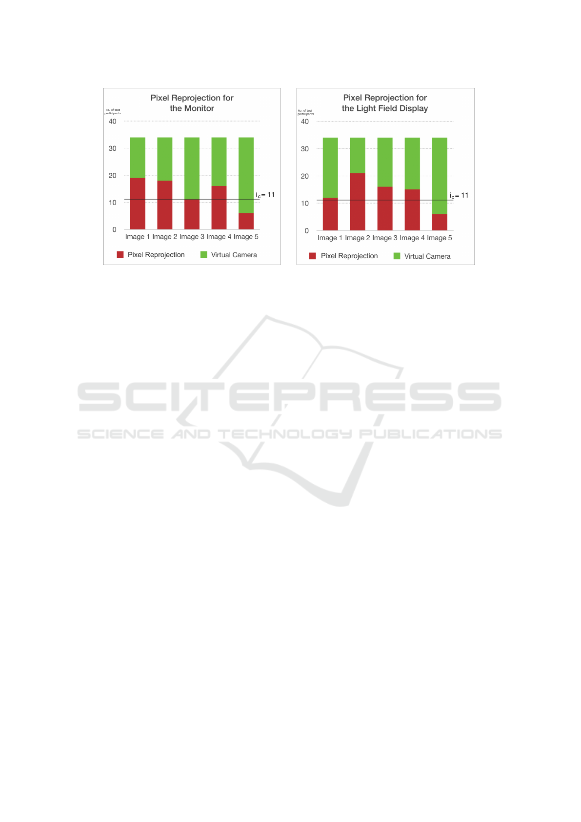
Figure 6: When 11 or more test participants choose PR, we can conclude that the test participants can do no better than a
random guess, and therefore that they do not see a differenec between VC and PR.
REFERENCES
Adelson, S. J. and Hodges, L. F. (1995). Generating ex-
act ray-traced animation frames by reprojection. IEEE
Computer Graphics and Applications, 15(3):43–52.
Borg, M., Johansen, S. S., Thomsen, D. L., and Kraus, M.
(2012). Practical implementation of a graphics turing
test. In International Symposium on Visual Comput-
ing, pages 305–313. Springer.
Cunningham, D. W. and Wallraven, C. (2011). Experimen-
tal design: From user studies to psychophysics. CRC
Press.
Havran, V., Damez, C., Myszkowski, K., and Seidel, H.-
P. (2003). An efficient spatio-temporal architecture
for animation rendering. In ACM SIGGRAPH 2003
Sketches & Applications, pages 1–1. ACM.
Hoffman, D. M., Girshick, A. R., Akeley, K., and Banks,
M. S. (2008). Vergence–accommodation conflicts hin-
der visual performance and cause visual fatigue. Jour-
nal of vision, 8(3):33.
Kang, S. B. (1998). Geometrically valid pixel reprojection
methods for novel view synthesis. ISPRS journal of
photogrammetry and remote sensing, 53(6):342–353.
Lanman, D. and Luebke, D. (2013). Near-eye light field
displays. ACM Transactions on Graphics (TOG),
32(6):220.
Levoy, M. (2006). Light fields and computational imaging.
IEEE Computer, 39(8):46–55.
Levoy, M. and Hanrahan, P. (1996). Light field rendering. In
Proceedings of the 23rd annual conference on Com-
puter graphics and interactive techniques, pages 31–
42. ACM.
McKee, S. P., Klein, S. A., and Teller, D. Y. (1985). Statis-
tical properties of forced-choice psychometric func-
tions: Implications of probit analysis. Perception &
Psychophysics, 37(4):286–298.
Nehab, D., Sander, P. V., Lawrence, J., Tatarchuk, N., and
Isidoro, J. R. (2007). Accelerating real-time shading
with reverse reprojection caching. In Graphics hard-
ware, volume 41, pages 61–62.
Rolland, J. and Hua, H. (2005). Head-mounted display sys-
tems. Encyclopedia of optical engineering, pages 1–
13.
Shibata, T., Kim, J., Hoffman, D. M., and Banks, M. S.
(2011). Visual discomfort with stereo displays: Ef-
fects of viewing distance and direction of vergence-
accommodation conflict. In IS&T/SPIE Electronic
Imaging, pages 78630P–78630P. International Society
for Optics and Photonics.
Sitthi-amorn, P., Lawrence, J., Yang, L., Sander, P. V., Ne-
hab, D., and Xi, J. (2008). Automated reprojection-
based pixel shader optimization. ACM Transactions
on Graphics (TOG), 27(5):127.
Suryakumar, R., Meyers, J. P., Irving, E. L., and Bobier,
W. R. (2007). Vergence accommodation and monoc-
ular closed loop blur accommodation have similar dy-
namic characteristics. Vision research, 47(3):327–
337.
Tawara, T., Myszkowski, K., and Seidel, H.-P. (2004). Ex-
ploiting temporal coherence in final gathering for dy-
namic scenes. In Computer Graphics International,
2004. Proceedings, pages 110–119. IEEE.
GRAPP 2017 - International Conference on Computer Graphics Theory and Applications
36
