An Interaction Framework for a Cooperation between Fully
Automated Vehicles and External Users in Semi-stationary Urban
Scenarios
Mohsen Sefati, Denny Gert, Kai Kreisköther and Achim Kampker
Chair of Production Engineering of E-Mobility Components, Campus-Boulevard 30, Aachen, Germany
Keywords: Automated Driving, Human-Machine-Interaction, Cooperative Automation, Interaction Framework, External
User.
Abstract: Automated vehicles are becoming gradually available in restricted environments and are planned to be
available for more challenging situations in the near future. Fully automated vehicles (FAVs) will have no
drivers and still need to cooperate and interact with other road users outside the vehicle. In this work we
propose an interaction framework, which makes it possible for external users to interfere with the FAV
guidance in an abstract level via communicating a desired maneuver. The external user can be assumed as a
road participant, who shares drivable areas with the FAV, or an operating person such as delivery person, who
wants to guide a delivery vehicle remotely. The application area of this framework is the low velocity range,
which can be also assumed as semi-stationary environments. The proposed framework explores the percepted
static environment and identifies all possible paths with respect to vehicle dynamics, safety and comfort
parameters. These paths are processed in order to build a set of meaningful candidates for the further steps.
For this goal we have proposed two different methods based on a modified RRT algorithm and a
skeletonization of the freespace. In order to extract possible drivable maneuvers out of the current scene, the
candidate paths are assigned to predefined maneuver classes and selected with respect to their length and
reasonableness. The set of meaningful and drivable maneuvers will be communicated to the user in form of
an abstract and simplified catalogue. With this framework we provide both the FAV and the external user
with a mutual understanding about the scene and avoid the possible ambiguity in goal understanding. The
proposed framework is validated with sensor data from real scenarios.
1 INTRODUCTION
In past decades the intelligence of automated vehicles
has increased evolutionary, so that fully automated
vehicles (FAV) are gradually available for defined
roadways in restricted environments (CityMobile2,
2016; WePods Project, 2016; Navya Shuttle, 2016).
With FAVs, we are addressing the highest automation
level, in which there is no need for the presence of a
human driver for monitoring the driving environment
or to interfere as a fallback layer, as it is defined in
the SAE-Level 5 (SAE international, 2014). Since the
driving task is a social behaviour, even in the absence
of a driver there is still a need to understand the
intention of other road participants and interact with
them. This interaction has two communication ways:
not only the FAV has
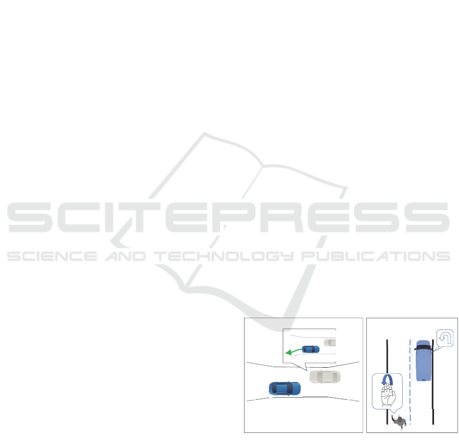
Figure 1: Examples of use-cases for interaction framework
with external users. a) Road user approaching the
automated vehicle in a narrow street and wishes to
communicate the backward maneuver. b) Operator wants to
assign a new position to the vehicle and ask the vehicle to
turn back.
Example:Narrowing
Scenario
FAV
Roaduser
Desiredmaneuver
a)
b)
Egovehicle
External
user
Sefati, M., Gert, D., Kreisköther, K. and Kampker, A.
An Interaction Framework for a Cooperation between Fully Automated Vehicles and External Users in Semi-stationary Urban Scenarios .
DOI: 10.5220/0006310301110120
In Proceedings of the 3rd International Conference on Vehicle Technology and Intelligent Transport Systems (VEHITS 2017), pages 111-120
ISBN: 978-989-758-242-4
Copyright © 2017 by SCITEPRESS – Science and Technology Publications, Lda. All rights reserved
111
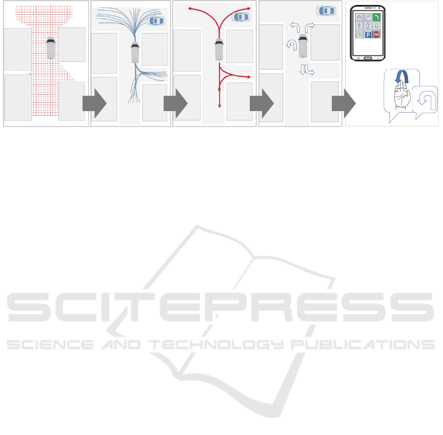
Figure 2: Maneuver extraction and mapping with the user commands.
to understand the intention of the road participant
based on its observation, but also the target person
should be able to communicate his goals and
intentions to the FAV explicitly. The interaction and
cooperative vehicle guidance based on the
observation and implicit intention estimation of the
other road users has been the focus of many research
activities recently (Ulbrich et al., 2015; Bahram et al.,
2016; Liu et al., 2015). In contrary, the direct and
explicit cooperation of the external road participant
with the FAV is usually overlooked, which is the
focus of this work. This type of interaction usually
happens in low speed scenarios.
The importance of this communication can be
identified in dead lock situations, which can be
caused due to the faulty perception or not general
validity in decision making of the FAV. In such a
situation the road participant cannot communicate a
possible solution to FAV, due to the absence of visual
interaction channels such as eye contacts and gesture
(Figure 1-a). Another example can be identified in use
cases of cooperative task execution, in which the
FAV should cooperate with an external operating
person, who is involved in a secondary task rather
than driving (e.g deliver person who cooperates with
fully automated delivery vehicle). In this case, the
operating person needs to communicate with the FAV
and interfere in vehicle guidance remotely (Figure 1-
b).
In this work we introduce an interaction framework
for the FAV and an external user (i.e. an operating
person or a road participant) at low velocities in urban
situations. This framework enables both the external
user and the FAV to have a mutual understanding
about the driving environment and inform the user
about the feasible action set through a formalized and
regulated communication. The user can interfere in
vehicle guidance at high-level without being
informed about the details of its driving environment.
This paper is structured as follows: After discussing
related works in chapter 2, an overview of the
presented approach is given in chapter 3. The
implementation is given in chapter 4 and results are
illustrated in chapter 5. Conclusions follow in the last
chapter.
2 RELATED WORKS
In field of robotics, the Human-Robot-Interaction
(HRI) has been widely studied. The HRI allows a
natural and effective interaction between human users
and robots using technologies such as speech and
gesture recognition. HRI has a wide range of
application in fields such as education, home and
rehabilitation for tele-operated and unmanned robots
(Tsai et al., 2009). In the context of driving, the
interaction between the driver and the automated
vehicle has been investigated in many research
activities recently. The H-Mode (Flemisch et al.,
2003; Kienle et al., 2009) and Conduct-By-Wire
(CbW) (Hakuli et al., 2010) are examples of such an
interaction. Both concepts address semi-autonomous
driving for urban and highway scenarios (i.e.
Automation Level 3 (SAE international, 2014)), in
which the driver is continuously involved with the
vehicle guidance via an active interface. Both
concepts are based on a maneuver-based approach,
which makes the guidance of the vehicle available by
means of maneuver commands instead of
conventional control elements such as steering, gas
and brake. Geyer has added a Gate-Concept to the
CbW-Framework which segments the vehicle
guidance task by identification of decision points
during the execution (Geyer, 2015). Lotz has
introduced a similar maneuver-based concept, which
delegates specific driving maneuvers like lane
PathExploring
Maneuver
Extraction
Creationof
ManeuverCatalogue
Smart
Device
Gestur
Communication
FreeSpace
Detection
VEHITS 2017 - 3rd International Conference on Vehicle Technology and Intelligent Transport Systems
112

changes or turns at intersections also on vehicle
guidance level (Lotz and Winner, 2014). In these
concepts, the vehicle should drive along a fixed
navigation route, and lane changes and turn
maneuvers are the focus of the research. Contrary to
the interaction concepts for the driver and automated
vehicles, there are only few examples available for an
explicit interaction between the automated vehicles
and external user. The FAV of the Google Car project
can check the presence cyclist and understand its
hand signal (Kretzschmar and Zhu, 2015). In the tele-
operated driving project from Technical University of
Munich, the subject vehicle can assist the operator
with communicating and executing the feasible paths,
which are extracted from the current scenes. The
operator can select between the available paths and
cooperate in vehicle guidance which also helps him
to overcome the communication delay (Hosseini et
al., 2014).
3 OVERVIEW OF THE
APPRAOCH
3.1 Problem Statement
The main idea of this work is to open an interaction
interface for the external user and make him possible
to interfere in the vehicle guidance explicitly and in a
discrete form from the limited distance. The
framework should not stress the user with the
workload and must be generally applicable also in
unknown traffic situations, also in absence of the
digital map.
There are two main use cases conceivable for this
framework. The first use case addresses conflict and
deadlock scenarios, in which the one road participant,
who shares the same driving area with FAV, wants to
interact explicitly in order to solve the situation. The
second use case refers to an external user near the
subject vehicle, who wants to navigate the vehicle to
the next desired point. Examples of this use case are
an operating person who wants to coordinate the
vehicles in the depot, or the delivery person who
wants to navigate the delivery vehicle to the next
delivery point, or the vehicle owner who wants to
guide the vehicle to the desired parking spot. These
use cases take place in the low velocity fields;
therefore, we assume it as semi-stationary.
The major challenge of this framework is to
provide both the user and the FAV with a mutual
understanding about the shared drivable area and
possible actions. Since the user might have a
restricted sight to the FAV, he might not be able to
interpret the situation correctly as the FAV does.
Furthermore, the FAV might not be able to map the
desired user command to the available action due to
the ambiguity in command understanding. Therefore,
it is necessary to provide the user with a standard list
of executable commands, which are extracted out of
the current scene understanding of the FAV. Each
command can be described as a simplification of a
chain of actions, which can be clustered into a
comprehensible single command for the user. The
user commands (in form of the gesture or signal in
case of use of smart devices) should be standardized
and mapped directly to standard actions, which
vanishes the ambiguity in communication. The
detection of the user feedback (gesture or a signal) is
not the focus of this work.
Figure 3: Functional architecture of the interaction
framework with the external user.
3.2 Functional Architecture of the
Concept
Inspired by (Geyer, 2013), we will also use a
maneuver-based approach for the cooperative vehicle
guidance for an interaction with the external user. The
framework provides the user with the set of standard
maneuvers, which are extracted from the current
scene. For each of this standard maneuver, there
could be an associated user command in form of a
gesture or considered signal. The creation of a
maneuver catalogue can be split into four main steps,
as illustrated in Figure 3. The first step is to detect
the drivable area and the static obstacles. Since we
only incorporate with dynamic obstacles during the
maneuver execution in later steps, we filter them
explicitly from the detected navigable spaces. The
User
Commands
StaticPerception
PathExploringin
stat.Environment
TrajectoryPlanning
indyn.
Environment
Maneuver
Extraction
Maneuver
Execution
SituationAnalysis
ManeuverCatalog
DynamicPerception
ManeuverList
An Interaction Framework for a Cooperation between Fully Automated Vehicles and External Users in Semi-stationary Urban Scenarios
113

output of this step is the static representation of the
environment in form of an occupancy grid, which is
used in the second step for the path exploring. Since
the FAV is not informed about the desired goal of the
external user yet, it has no target pose for calculating
the maneuver respectively. Therefore, it calculates
multiple possible drivable paths, which can be
pursued in the detected drivable area. As a result, the
number of paths has to be reduced to a smaller set of
meaningful paths, from which the final maneuvers are
selected that will be communicated to the external
user. In order to perform this reduction, paths leading
to the same destination will be clustered together.
Short paths, which cannot be assigned to a specific
standard maneuver in the current scene will not be
considered further. Subsequently, the remaining
paths will be mapped to the predefined set of
maneuvers by geometrical considerations.
The total functional architecture of the interaction
framework is illustrated in Figure 3. The user will be
provided with a set of standard maneuvers extracted
from the current scene based on the bottom-up
approach. After the user communicates his desired
command, the FAV has to analyse the situation
including the dynamic obstacles. The future
behaviour of the other road participants with respect
to the actual context has to be estimated. Furthermore,
the collision risk for the desired maneuver has to be
evaluated. Based on this information, the FAV can
recalculate the maneuver and split it into more ones
for a feasible execution. The output will be forwarded
to the trajectory planning module for the fine
planning.
4 BUILDING THE MANEUVER
CATALOG
The following subchapters deal with the construction
of the maneuver catalogue (cp. Fig. 3). It is required,
that this catalogue provides maneuvers, that are
drivable on one hand – concerning vehicle dynamics
and collisions with the static environment – and
meaningful on the other hand. In this context,
‘meaningful’ relates to a path that a human driver
would have chosen concerning the topology of the
drivable area. For example, a path should not end
directly in front of a wall or be curvier than necessary.
It is inherent to the idea of proposing drivable
maneuvers, that a set of candidate paths must be
determined before a specific target position is given
(cp. ‘Path Exploring’ in Fig. 2). This is contrary to the
common path planning task, which aims at following
a given route.
In order to generate a set of maneuver proposals,
we compute a set of candidate paths without given
goal positions. Once this set of candidate paths has
been determined, a subset is chosen by comparison
with a predefined maneuver set. In order to generate
the candidate set, we have investigated several
approaches that can be assigned to two categories,
which differ in the way of handling the absence of a-
priori known goal positions. The first category aims
at generating a large number of paths leading into the
freespace and subsequently selects some of these
paths. Each selected path implies a goal position
through its endpoint. The second category aims at
determining meaningful goal positions by an analysis
of the environment first, and subsequently applies a
classical path search algorithm in order to find a path
leading to each goal position that has been
determined. Once a proposed maneuver is chosen by
the external user, the respective path serves as an
initial solution for calculating the actual trajectory in
detail (e.g. by numerical optimization), that is passed
to the control level of the FAV.
In the following subchapters, we present two
approaches to generate candidate paths, one from
each category. In addition to that, the representation
of the static environment as prerequisite of this
framework and the final construction of the maneuver
catalogue will be addressed in the following.
4.1 Static Environment Model
The static environment is represented as a 2D
occupancy grid, composed of quadratic grid-cells
.
Each cell is updated according to new sensor data by
individual Bayes Filter updates as described in (Thurn
et al., 2006)
,
,
log
|z
,
1
|
,
log
1
(1)
with
,
log
|
:
,
:
1
|
:
,
:
(2)
where
,
is the log odds representation of the
occupancy probability at timestep k.
denotes the
range measurements and
denotes the FAV’s
position, which is assumed to be known by
measurements. In order to filter spurious elements
from the occupancy map, that might be caused by
measurements associated to moving objects if the
FAV is not equipped with a radar sensor, we follow
VEHITS 2017 - 3rd International Conference on Vehicle Technology and Intelligent Transport Systems
114

the method proposed in (Schreier et al., 2016). In each
iteration, ‘newly-free’ and ‘newly-occupied’ grid
cells can be determined by threshholding the change
in the log odds w.r.t to the previous time-step. By
making geometrical considerations, these cells can be
merged and enclosed by a rectangular bounding box,
which is treated as a potential dynamic object. This
hypothesis is further investigated by filtering the
observations over time with help of an Interacting-
Multiple-Model in combination with a Probabilistic
Data Association Filter (see (Schreier et al., 2016) for
details). From this procedure, a probabilistic
evaluation for the validity of the dynamic object
hypothesis can be obtained, such that sensor evidence
for grid-cells classified as dynamic can be deleted
from the occupancy map. The planning space for
determining the maneuver catalogue is set as a
quadratic region with sides up to 100 meters, having
the FAV in the center. The size of a grid-cell is 0.2 m.
Given the occupancy map , a binary representation
can be constructed by threshholding the log odds.
Further, a distance grid can be obtained by an
Euclidean distance transform
min
∈
,
‖
‖
,
EDT
(3)
by applying a linear-time algorithm introduced in
(Felzenszwalb and Huttenlocher, 2012). Given the
distance grid , we can obtain an artificial potential
field as the logarithmic inverse distance transform
log
.
(4)
All grids m, d and a are only given as sampled
functions, respectively as two-dimensional arrays at
discrete grid-points ∈.
4.2 Path Explorng By Modified RRT
The original RRT algorithm introduced in (Lavalle,
1999) as well as its extension to RRT*, further treated
in (Karaman and Frazzoli, 2011), is a randomized
search that iteratively extends a search tree, where
each node in the search tree corresponds to a vehicle
state in the planning space. Respectively, a path from
the root to a leaf node corresponds to a possible path
for the FAV to drive. It is typical for randomized path
search algorithms, that the quality of the solution path
(e.g. the shortest path leading to a given goal position)
grows with the number of iterations, due to a deeper
exploration of the search space. A large variety of
Figure 4: Illustration of the keysteps of the RRT algorithm.
extensions and modifications have been developed
since the original RRT algorithm has been proposed,
which typically aim at increasing the quality of the
solution path with respect to the runtime, often by
goal-biased sampling techniques. Nevertheless, the
RRT algorithm does not explicitly require a goal
position to operate, which makes it particularly
suitable for our use case. Therefore, we design our
RRT algorithm in order to produce a large number of
high quality paths quickly, rather than aiming for a
single high quality solution path.
Figure 4 illustrates the keysteps of one iteration of
the basic RRT algorithm. The SAMPLING function
randomly generates a new sample node in the
planning space. The NEAREST function determines a
node in the search tree, to which a new path will be
appended that leads towards the sample node. This
new path is determined by the EXTEND function. In
the following we address the modifications for these
keysteps that we have implemented in order to
generate candidate paths.
The SAMPLING is performed in a polar region
around the FAV as depicted in Figure 5 with
=
45 m and
= 50 m.
Figure 5: Illustration of the sampling pattern for each search
tree (right) and an exemplary turnaround maneuver, serving
as bridge between initial positions of the separate search
trees.
N
EAREST
S
AMPLING
EXTEND
r
min
r
max
An Interaction Framework for a Cooperation between Fully Automated Vehicles and External Users in Semi-stationary Urban Scenarios
115

Two different search trees are built independently
for both sampling regions front and back, depicted in
green and red. Let the real vehicle pose
,,
at
calculation time correspond to the green scenario.
The calculation for the red sampling region is
performed in parallel on a second thread with the
artificial initial pose
,,
. The corresponding
turnaround maneuver, illustrated in Figure 5, can be
computed afterwards or simultaneously on a third
thread by an A*-Search on a lattice, as briefly
addressed in subchapter 4.4. In addition to the parallel
computation of the two different trees, referred to as
“OR-Parallelization” (Carpin and Pagello, 2002),
more parallel workers can contribute to the
calculation of each separate tree, referred to as
“AND-Parallelization”. If the turnaround maneuver is
not possible, e.g. due to a limited free-space, paths of
the red tree can be used to propose reverse-drive
maneuvers. Otherwise, they can be used for both
reverse-drive and turnaround follow-ups, as will be
addressed further in subchapter 4.4.
For EXTEND, we use forward simulations of a
dynamic single track model
, with state
vector
denoting slip angle ,
heading rate , heading angle and position
coordinates x, y. The input variable refers to the
steering angle. In order to append new paths to the
search tree, simulations are performed for a fixed
number of time-steps with predefined steering angle
increments ∆
∈, 1,…, keeping l
fixed for each extension. A simulation is aborted if
either a -neighbourhood of the sample node has been
reached or a collision has occurred:
EXTEND(
,
,
,
1 for l = 1:m
2
,
3
,
4 for k = 1:n
5
,
,
∆
6
,
←
,
,
,
7 if(collision(
,
{
8
,
inf
9 break
10 } else {
11
,
←
,
,
,
,
12 }
13 if(reach(
,
,
,
, break
;
14 end for
15 end for
16 ←min
C
,
17 addpath(
:,
,
,
From the predefined steering increments, the best
one is determined according to the cost
,
,
,, evaluating the simulated vehicle
states
at integration step k and the position
coordinates of the sample node
,
,
,
,
e
,
,
α
∙
∙
(5)
with squared Euclidean distance
e
,
,
,
(6)
the value of the artificial potential field (cp. eq. 4)
evaluated for the grid point determined by rounding
the position to the nearest integer coordinates
,←
,
,
(7)
and the cumulated absolute steering effort
∙
|
∆
|
.
(8)
, ∈ are weighting parameters. For the
NEAREST function, we use the j-th predecessor of the
nearest leaf node of the tree, where ‘nearest’ is
determined by the Euclidean distance metric with
respect to the (x,y,)-space, where denotes the
cumulated absolute steering effort measured from the
root to the respective leaf node. ∈ is a parameter
of choice, e.g. j = 2.
In order to prepare a smaller set of candidate paths
for the further generation of the maneuver catalogue,
endpoints of computed paths are clustered by
applying a k-means clustering algorithm as proposed
in (Hosseini et al., 2014). From each cluster, only one
path is kept, that is the one with the smallest .
4.3 Path Exploring by Skeletonization
This subchapter deals with an alternative method to
the previously proposed Path Exploring with help of
the modified RRT algorithm. The need for an
alternative method arises from the missing property
of probabilistic completeness with respect to feasible
goal states in the sampling region, resulting in the
possibility that the modified RRT will miss possible
paths even for long runtimes. The basic idea of the
approach in this subchapter is to choose reasonable
goal positions from junctions in the skeleton
representation of the free-space, and to subsequently
search for a path leading to this goal region.
Skeletonization is a widely applied technique in
image processing, leaving a ‘thin version’ of the
shape contained in the original image while
representing certain geometric and topologic
properties. A great number of efficient algorithms
have been developed for this purpose, just one famous
VEHITS 2017 - 3rd International Conference on Vehicle Technology and Intelligent Transport Systems
116

representative can be found in (Zhang and Suen,
1984). In order to calculate the skeleton, the
occupancy grid is converted into a binary image by
threshholding, where unknown areas are considered
as free-space. From the resulting skeleton, pixel
coordinates of junctions can be obtained by applying
an image based edge detection. In order to select
distinct goal regions for a subsequent path search, we
use a DBSCAN-clustering to ‘merge’ detected
corners that lie very close to each other by replacing
them with the respective cluster midpoint. A cluster
midpoint is accepted as a goal position, if the
associated value in the potential field (cp. eq. 4)
undergoes a threshold and is sufficiently far away
from the FAV’s position.
Once the goal positions have been determined, a
traditional path search is applied to find a path from
the FAV’s current position to the goal positions. As
the search must be performed for multiple target
positions, the most important property of the path
search algorithm that is chosen is the computational
runtime. The quality of the obtained path is of minor
interest, as it will not be executed by the FAV but only
serves as proposal. A fast but sufficiently accurate
method can be obtained by running a standard A*
graph search on an individually constructed lattice,
where the complexity of the lattice is the result of a
trade-off between path quality and computation time.
A graph representation of the lattice can be offline
constructed recursively by solving a two-point
Figure 6: Illustration of a solved boundary value problem
connecting
to
(top). The bottom depicts a 2D
projection of a recursively constructed state lattice.
boundary value problem calculating a path from a
starting node
,
,
to several target nodes
(cp. Figure 6) as addressed in (Pivtoraiko et al.,
2009). For each solution, the target node and the
respective path will be added to a graph as new
vertices and corresponding edges. Subsequently, the
procedure is recursively called setting the target
nodes of each solution as
in the recursive calls. In
order to solve the two-point boundary value
problems, we use clothoid segments calculated by the
fitting method proposed in (Bertolazzi and Frego,
2012), ruling out solutions that violate maximum
length and curvature constraints.
Figure 6 depicts a two dimensional projection of
an exemplary lattice, such that nodes are only
represented by their position coordinates. The number
of target nodes
as well as the recursion depth are
parameters in the graph construction, that can be
easily adjusted to emphasize a faster runtime or the
quality of obtained paths respectively. For computing
the turnaround maneuver (cp. Figure 5), reverse edges
must be considered in the graph construction.
Figure 7: Illustration of the considered maneuvers and
associated polar regions. denotes the FAV’s orientation
and denotes the endpoint-orientation of a computed
candidate path relative to the FAV.
4.4 Maneuver Extraction
The output of the Path Exploring is a set of candidate
paths. The goal of the Maneuver Extraction is to
compare this set of candidate paths to a predefined
maneuver set in order to determine, which of the
predefined maneuvers can be executed and therefore
can be proposed to the external user in the maneuver
catalogue (cp. Figure 7).
For making this selection, each predefined
maneuver is associated to a polar region around the
FAV, defined by an interval
,
for each
r
min
An Interaction Framework for a Cooperation between Fully Automated Vehicles and External Users in Semi-stationary Urban Scenarios
117
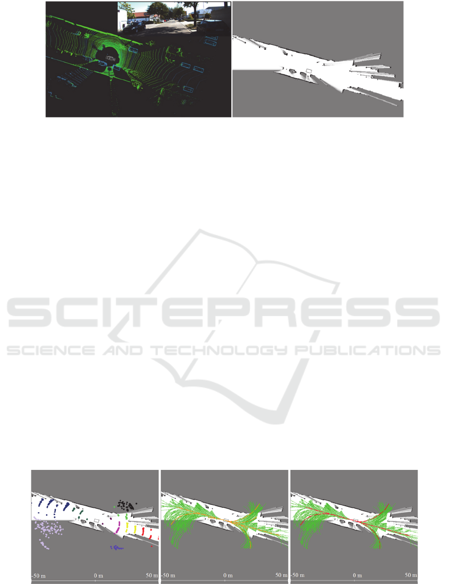
Figure 8: Stereo Camera View and Pointcloud obtained by a Velodyne HDL-64E Sensor recorded in the Kitti-Dataset (Geiger
et al., 2013) (left). The right picture depicts the 2D occupancy grid representation of the test scene.
region, and the minimum radius
as illustrated in
Figure 7. Every region additionally has an associated
interval
,
addressing a range for valid
vehicle orientations. A maneuver is classified as
executable and therefore contained in the final
catalogue, if the endpoint of at least one candidate
path lies inside the respective region and the
associated vehicle orientation is in the valid range. If
multiple endpoints of candidate paths are present in
the same region, the longest path satisfying the above
conditions is associated to the respective maneuver.
The turnaround followup maneuvers, labelled in blue
in Figure 7, are considered as possible, if the
respective reverse drive maneuvers, labelled in dark
grey, are feasible and a turnaround maneuver has
been successfully computed.
5 RESULTS
In order to investigate the behavior of the described
procedure for urban traffic scenarios, we have used
sensor data offered by the Kitti database (Geiger et
al., 2013) as inputs for our implementation. Figure 8
illustrates one scenario, in which the ego vehicle is
driving along a narrow street, approaching two
driveways to the left and right. From the ego vehicles
position in that scene, we expect the algorithm to
propose maneuvers continuing the straight road
course, as well as taking the driveways to both sides.
Further opportunities are given in this scene by the
reverse direction. Below, results from both presented
algorithms are depicted, but for a different size of the
planning area. In case of the modified RRT, the
quadratic area is sized 100x100 meters. In case of the
skeletonization approach, the area is limited to 50x50
meters. The RRT approach offers a much greater
opportunity for parallelization, which is limited for
the skeletonization method. Figure 9 depicts the
candidate trajectories generated by the modified RRT
(mid), as well as the clustered endpoints (left) and the
extracted maneuver paths (right). Comparing the
maneuver paths with the ones obtained by the
skeletonization method, depicted in Figure 10 (right),
it can be observed that both algorithms are able to
propose paths taking the driveways to the left and
right, but paths differ in shape. Clearly, the effect of
the cost function eq. (5) of the modified RRT can be
identified, resulting in maneuver proposals that are
less curvy compared with the paths generated by the
lattice A*-search, which is aiming for the shortest
path to the identified goal positions. This effect is
even more emphasized in case of the straight forward
and straight reverse maneuvers. As our framework
Figure 9: Green paths are raw paths generated by the modified RRT. The orange paths (mid) are candidate trajectories,
determined for each cluster, which are depicted right. The red paths (right) are the result of the maneuver extraction and
correspond to paths in the maneuver catalogue.
VEHITS 2017 - 3rd International Conference on Vehicle Technology and Intelligent Transport Systems
118
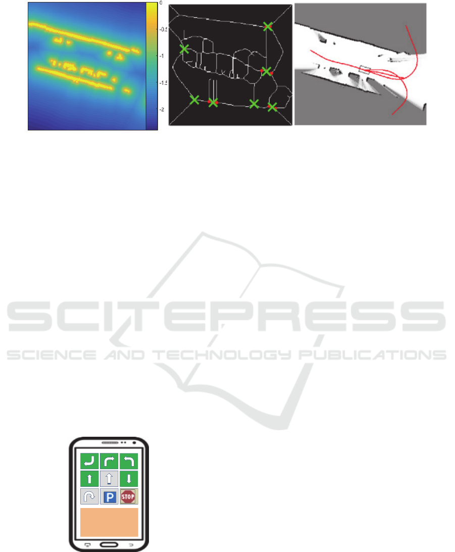
Figure 10: The middle image depicts the skeleton of the free-space. Crosses denote selected endpoints from clustering detected
corners, that correspond to a sufficient low cost on the potential field (left). The red paths (right) are the result of the maneuver
extraction and correspond to paths contained in the maneuver catalogue.
intends to propose maneuvers on an abstract high-
level, the curvier paths generated by the A*-search do
not change the proposals contained in the maneuver
catalogue. The missing proposal of a reverse-drive
turn in case of the skeletonization method is due to
the limited planning region, but has been addressed
by a respective goal region (cp. Figure 10 middle).
Nevertheless, the difference in paths’ shapes affects
the execution of a maneuver once it has been selected,
depending on the algorithms used for the trajectory
planning and control of the FAV. Further, we aim to
replace the method for evaluating candidate paths by
predefined regions and maneuver classes (cp. ch. 4.4)
by more generic algorithms that evaluate shapes of
candidate paths directly, rather than focusing on
endpoints.
The output of the framework can be illustrated for
user in an abstract form, for example in a smart device
as it is sketched in Figure 11. The green maneuvers
are available and can be executed after selecting by
user.
Figure 11: An example of user interface for communicating
the abstract maneuvers in form of a standard catalogue.
6 CONCLUSIONS AND FUTURE
WORKS
This paper presents a new interaction framework for
the cooperation between the external user out of the
FAVs based on a maneuver based approach. This
framework provides the external user with an abstract
and simplified drivable maneuver catalog, which is
extracted out the current scene perception. The
extraction leads to the mutual understanding between
the user and the FAV about the environment and
avoids ambiguous in goal communication. The user
can use the catalog in order to interact and navigate
the vehicle in a discrete way to the desired position.
In order to create the maneuver catalog, a set of
trajectories has been taken into account and filtered
with respect to quality factors. In order to calculate
the candidate paths, two different approaches have
been proposed, which are based on modified RRT and
Skeletonization.
In the future work, the proposed framework will
be extended with considering the further maneuvers
such as follow me and parking. Moreover, the
combination of the maneuver and the communication
of chain of maneuvers will be taken into account.
REFERENCES
Bahram, M., Lawitzky, A., Friedrichs, J., Aeberhard, M.
and Wollherr, D. , 2016 . A Game-Theoretic Approach
to Replanning-Aware Interactive Scene Prediction and
Planning, In IEEE Transactions on Vehicular
Technology, VOL. 65, 3981–3992.
Bertolazzi, E. and Frego, M. , 2012 . Fast and Accurate
Clothoid Fitting, In ACM Transactions on
Mathematical Software.
Pleaseselectthe
desired
maneuver
An Interaction Framework for a Cooperation between Fully Automated Vehicles and External Users in Semi-stationary Urban Scenarios
119

Carpin, S. and Pagello, E. , 2002 . On Parallel RRTs for
Multi-robot Systems, In Proc. of the 8th conference of
the Italian Association for Artificial Intelligence, 834–
841.
CityMobile2 , 2016 . Cities demonstrating and automated
road passenger transport. http://www.citymobil2.eu/en/
(Accessed 15 December 2016).
Felzenszwalb, P.F. and Huttenlocher, D.P. , 2012 . Distance
Transforms of Sampled Functions, In Theory of
Computing, Volume 8, 415–428.
Flemisch, F., Adams, C., Conwary, S., Goodrich, K.,
Palmer, M. and Paul Shutte , 2003 . The H-Metaphor as
a guideline for vehicle automation and interaction,
Virginia, NASA/TM-2003-212672.
Geiger, A., Lenz, P., Stiller, C. and Urtasun, R. , 2013 .
Vision meets Robotics: The KITTI Dataset, In
International Journal of Robotics Research (IJRR).
Geyer, S. , 2015 . Entwicklung und Evaluierung eines
kooperativen Interaktionskonzepts an
Entscheidungspunkten für die teilautomatisierte,
manöverbasierte Fahrzeugführung, Dissertation,
Institute for Automotive Engineering, Technische
Universität Darmstadt.
Geyer, S. , 2013 . Maneuver-based vehicle guidance based
on the Conduct-by-Wire principle, Springer Verlag,
Berlin u.a., In Automotive Systems Engineering.
Hakuli, S., Kluin, M., Geyer, S. and Winner, H. , 2010 .
Development and Validation of Manoeuvre-Based
Driver Assistance Functions for Conduct-by-Wire with
IPG CarMaker, Budapest, In FISITA 2010 World
Automotive Congress.
Hosseini, A., Wiedemann, T. and Lienkamp, M. , 2014 .
Interactive path planning for teleoperated road vehicles
in urban environments, In IEEE 17th International
Conference onIntelligent Transportation Systems
(ITSC).
Karaman, S. and Frazzoli, E. , 2011 . Sampling-based
Algorithms for Optimal Motion Planning, In
Internation Journal of Robotic Research, Vol. 30,
No. 7, 267–274.
Kienle, M., Damböck, D., Kelsch, J., Flemisch, F. and
Bengler, K. , 2009 . Towards an H-Mode for highly
automated vehicles: Driving with side sticks, In 1st
International Conference on Automotive User
Interfaces and Interactive Vehicular Applications
AutomotiveUI '09.
Kretzschmar, H. and Zhu, J. , 2015 . Cyclist hand signal
detection by an autonomous vehicle, US9014905 B1.
Lavalle, S.M. , 1999 . Rapidly-Exploring Random Trees: A
New Tool for Path Planning.
Liu, W., Kim, S.-W., Pendleton, S. and H. Ang, M. , 2015 .
Situation-aware decision making for autonomous
driving on urban road using online POMDP, IEEE, In
Intelligent Vehicles Symposium (IV).
Lotz, F. and Winner, H. , 2014 . Maneuver delegation and
planning for automated vehicles at multi-lane road
intersections, IEEE, In 17th International Conference
on Intelligent Transportation Systems (ITSC).
Navya Shuttle , 2016 . Navya Shuttle. http://navya.tech
(Accessed 15 December 2016).
Pivtoraiko, M., Knepper, R.A. and Kelly, A. , 2009 .
Differentially Constrained Mobile Robot Motion
Planning in State Lattices, In Journal of Field Robotics,
Vol. 26, 308–333.
SAE international , 2014 . Taxonomy and definitions for
terms.
Schreier, M., Willert, V. and Adamy, J. , 2016 . Compact
Reperesentation of Dynamic Driving Enviroments for
ADAS by Parametric Free Space and Dynamic Object
Maps, In Transactions on Intelligent Transportation
Systems, Vol 17, No. 2, 367–384.
Thurn, S., Burghard, W. and Fox, D. , 2006 . Probabilistic
Robotics.
Tsai, C.-C., Hsieh, S.-M., Hsu, Y.-P. and Wang, Y.-S. ,
2009 . Human-Robot Interaction of an Active Mobile
Robotic Assistant in Intelligent Space Environments, In
International Conference on Systems, Man and
Cybernetics, 978-1-4244-2794-9/09/$25.00 ©2009
IEEE, 1953–1958.
Ulbrich, S., Grossjohann, S., Appelt, C., Homeier, K.,
Rieken, J. and Maurer, M. , 2015 . Structuring
Cooperative Behavior Planning Implementations for
Automated Driving, In IEEE 18th International
Conference on Intelligent Transportation Systems.
WePods Project , 2016 . The first autonomous vehicle on
Dutch public roads: The WEpods in Ede and
Wageningen. http://wepods.nl/ (Accessed 15 December
2016).
Zhang, T.Y. and Suen, C.Y. , 1984 . A Fast Parallel
Algorithm for Thinning Digital Patterns, In
Communications of the ACM, Volume 27, 236–239.
VEHITS 2017 - 3rd International Conference on Vehicle Technology and Intelligent Transport Systems
120
