
Semi-automated Business Process Model Matching and Merging
Considering Advanced Modeling Constraints
Markus C. Beutel
1,2
, Vasil Borozanov
1
, Sevket G
¨
okay
1,2
and Karl-Heinz Krempels
1,2
1
Informatik 5 (Information Systems), RWTH Aachen University, Aachen, Germany
2
CSCW Mobility, Fraunhofer FIT, Aachen, Germany
Keywords:
Business Process Modeling, Model Merging, BPMN 2.0, Constraints.
Abstract:
Model merging helps to manage the combination and coevolution of business processes. Combining models
(semi-)automatically can be a helpful technique in manifold areas and has been investigated since decades by
the scientific community. The rising complexity of (business-) processes in shifting environments demands
for a more differentiated view on model matching and merging techniques.
In this domain, we identified the problem of considering additional constraints in the matching and merging
process and suggest an approach by adapting state of the art solutions correspondingly. In addition, we state
necessary reduction rules and discuss their suitability. Moreover we provide a prototypical implementation of a
matching and merging tool, which allows further investigations of the approach concerning quality, usefulness
and efficiency.
1 INTRODUCTION
Combining various kinds of models automatically is
still a prominent research field. Depending on the pro-
blem domain, manifold values might occur. (La Rosa
et al., 2013) declare that “the purpose of merged mo-
dels is to allow analysts to view the commonalities
and differences between multiple variants of a busi-
ness process and to manage their coevolution and con-
vergence”. (Nejati et al., 2007) conclude that model
matching and merging play a central role in suppor-
ting distribution and coordination of modeling tasks.
Moreover, ”merged models are intended for analysts
who want to create a model that subsumes a collection
of process models with the aim of replacing variants
with the merged model” (La Rosa et al., 2013).
But whereas nowadays, advanced modeling lan-
guages are extensive tools, offering manifold opera-
tors and elements to model complex systems, model
merging does not cover every modeling aspect yet.
In conjunction with shifting business environments,
changing firm structures or IT-system integration sce-
narios, business processes might be modified, com-
plemented or optimized. Coping with a continuous
change, improvement and re-engineering of business
processes with the help of modeling techniques has
been investigated by the scientific community since
decades. One example that clarifies the problem is
project Mobility Broker (Beutel et al., 2015), (Kluth
et al., 2015), where similar service processes have to
be integrated and consolidated.
Pre-eminently, we want to investigate the suita-
bility of semi-automated, graph based matching and
merging of business process models in complex sce-
narios. As a consequence, we consider additional mo-
deling constraints. Therefore, we review and extend
existing solutions. On hand of a specific use case, we
analyze how additional constraints affect the merging
results.
For example, incorporating different roles, repre-
sented by swimlanes in the Business Process Model
and Notation (BPMN) language into the merging pro-
cess widens the scope. This effort goes beyond invol-
ving interfaces into model merging, but incorporates
roles, their (sub-)processes and their messages flow
types. In fact, this affects the whole merging process
fundamentally.
Within this work, we present an approach for mo-
del merging, allowing to incorporate multiple advan-
ced modeling constraints. In addition, we show an
initial prototypical tool and discuss it’s suitability.
The remainder of this work is structured as fol-
lows. Section 2 describes the relevant theoretical ba-
sis. Afterwards, Section 3 describes the merging ap-
proach considering additional modeling constraints.
Section 4 presents the technical realization in form
324
Beutel, M., Borozanov, V., Gökay, S. and Krempels, K-H.
Semi-automated Business Process Model Matching and Merging Considering Advanced Modeling Constraints.
DOI: 10.5220/0006341603240331
In Proceedings of the 19th International Conference on Enterprise Information Systems (ICEIS 2017) - Volume 1, pages 324-331
ISBN: 978-989-758-247-9
Copyright © 2017 by SCITEPRESS – Science and Technology Publications, Lda. All rights reserved

of a merging tool. Section 5 shows the outcome of
our solution based on a exemplary use case. Finally,
Section 6 reflects and concludes the work.
2 FOUNDATIONS
This section describes the fundamentals concerning
business modeling, matching and merging.
2.1 Business Process Modeling
Languages
Process modeling is supposed to be an instrument for
coping with the complexity of process planing, with
importance for many purposes besides the develop-
ment of software (Becker et al., 2002). Business pro-
cess models help to improve and to re-engineer pro-
cesses. Vital for this purpose are models which help to
identify process weaknesses and allow an automated
comparison of new scenarios (Becker et al., 2003).
BPMN is a modeling language, using events and
activities to visualize (business-) processes. It descri-
bes the logic of process flows with the help of ga-
teway operators such as AND, OR and XOR
1
. Se-
quence flow, message flow and association elements
are used to describe the connection between certain
process objects (Kocian, 2011). In addition, swim-
lanes represent different roles, which allow to visu-
alize role-specific processes and their interdependen-
cies between each other in parallel.
Another prominent way of modeling processes is
Event-driven Process Chain (EPC). An EPC diagram
is a flowchart based diagram, used for resource plan-
ning and identifying possible improvements of a bu-
siness process (Object Management Group, 2016).
There are various other modeling techniques as well.
For the following explanations, we refer to the BPMN
2.0 standard.
2.2 Model Matching and Merging
In general, model matching and merging had already
been investigated in various modeling areas. For ex-
ample, (Brunet et al., 2006) show merging approa-
ches of entity relationship diagrams or state machi-
nes. Moreover, (Melnik, 2004) investigates the mat-
ching and merging of conceptual database schemata,
(Mandelin et al., 2006) proposes a technique for ma-
tching system architecture diagrams, using machine
learning and (Nejati et al., 2007) provide an approach
1
Exclusive or: True only, when one input is true and the
other is false.
for matching and merging statecharts specifications.
In general, (Brunet et al., 2006) describe model mer-
ging as an exploratory process, in which the goal is to
discover the exact nature of relationship between mo-
dels, as much as to combine them. Model merging is
facilitated by a number of related operations on mo-
dels, such as comparing, checking their consistency
and finding matches between them.
For our descriptions, we distinguish the operators
of matching and merging and refer to a business pro-
cess graph setting. Therefore, we use the following
definitions:
• A business process graph G is a set of pairs
of process model notes – each pair denoting
a direct edge. A node v of G is a tuple
(id
G
(v), λ
G
(v), τ
G
(v)) consisting of a unique iden-
tifier id
G
(v) within G, a label λ
G
(v) and a type
τ
G
(v) (La Rosa et al., 2013).
• Given process graphs G
1
, G
2
and nodes v ∈ G
1
,
w ∈ G
2
, process model matching is defined as
finding an injective mapping f (v, w) : v → w,
where f (v, w) is a scoring function and its value
is within the interval [0, 1] ⊂ R. This operation is
used to find commonalities between models (Bru-
net et al., 2006).
• Given n process graphs, process model merging
describes the reduction to k graphs (k < n), such
that the behavior and correctness is preserved.
In the specific field of interest of business pro-
cesses some valuable research has been done alre-
ady. (Kuester et al., 2008) suggest a process merging
tool that detects and resolves changes between pro-
cess models, which has limited applicability concer-
ning recent modeling languages. In addition, they fo-
cus more on the user-friendly design of their solution.
(La Rosa et al., 2013) provide a merging algorithm
for business process graphs. They explicitly abstract
from any specific notation, which increases the appli-
cability of the approach.
We base our studies on these findings and adapt
the algorithm correspondingly to our specific area of
interest.
3 APPROACH
We convert BPMN models to graphs. The approach
for merging the graphs consists of three main steps
(Figure 1):
1. Matching: Discovering similar parts of the graphs
and building a similarity map, which is passed on
to the next step.
Semi-automated Business Process Model Matching and Merging Considering Advanced Modeling Constraints
325

Matching
• Similarity
• Most Common
Regions
(MCR)
Merging
• Algorithm
Reduction
• Reduction
Rules
Figure 1: Merging process steps.
2. Merging: Traversal of the two graphs and based
on the similarity map, addition of the nodes to the
resulting merged graph.
3. Reduction: A clean-up of the merged graph since
there might be unnecessary/obsolete nodes, which
can be left out.
3.1 Matching
A business process is modeled as a directed graph
G = (V, E), where V is the set of nodes and E is the
set of edges such that for v, w ∈ V there is an edge
e = (v, w) ∈ E. A node can represent, for example, a
task or an event. An edge can represent, for example,
a message or sequence flow. Both nodes and edges
may hold any number of additional properties, which
are modeled as key-value pairs (Figure 2).
v
(k
3
, v
3
)
(k
4
, v
4
)
.
.
.
e
1
(k
1
, v
1
)
(k
2
, v
2
)
.
.
.
e
2
(k
5
, v
5
)
(k
6
, v
6
)
.
.
.
Figure 2: A graph node with incoming and outgoing edges.
Example. Consider a check availability process in
a sales company of goods. This process takes the
product identifier as input and returns the number of
items that are in stock. This can be modeled as de-
picted in Figure 3. In this example, the process be-
comes the node which contains the property (title,
Check Availability). The incoming edge contains the
property (input, product id), the outgoing edge con-
tains the property (output, number of items).
p
ca
(title, Check Availability)
(input, product id) (output, number of items)
Figure 3: Modeling example for a check availability process
Definition 1 (Element). An element is the building
block of a graph and can be either a node or an edge.
Definition 2 (Element similarity). Two elements are
similar, if
1. they hold the same property keys,
2. for every property key, the corresponding pro-
perty values are similar according to a similarity
function.
Definition 3 (Matching). Given process graphs G
1
,
G
2
and nodes v ∈ V (G
1
), w ∈ V (G
2
); we claim v and
w are matching, if
• v and w are similar,
• there is a bijection between the sets of the inco-
ming edge(s) of v and w, where the corresponding
elements are similar,
• there is a bijection between the sets of the out-
going edge(s) of v and w, where the corresponding
elements are similar.
Considering the example in Figure 3, if a diffe-
rent business process graph has a check availability
process, where the node contains the property (title,
Check Availability), incoming edge the property (in-
put, product id) and the outgoing edge the property
(output, number of items), then we say that both
check availability processes are matching.
Similarity Function
To identify the similarity between the values of two
properties with the same key, a similarity function is
required. Since the property keys might have varying
importance depending on the application domain, we
assign a similarity threshold to each key, which is
used to check whether the result of the similarity
function is acceptable or not. We conclude that the
two properties are similar, only if the result is above
this particular threshold. This requirement affects the
modeling of properties as key-value pairs, since every
key k becomes a pair k = (k
id
, k
t
), such that k
id
uni-
quely identifies the property and k
t
denotes the thres-
hold value for the similarity score.
Moreover, each key might dictate a different kind
of similarity function. For example, a key with a tex-
tual value might require an exact or a partial match.
Therefore, we extend the key representation to ex-
press this information as well, and k becomes a tuple
k = (k
id
, k
t
, k
sim
), such that k
sim
denotes the similarity
function to be used for this key.
For properties with textual value that require an
exact match, we look at the equality of both values.
For example, in the context of BPMN, the nodes
contain a type parameter, which is assigned to one
of {event, gateway, task, role}, and the edges con-
tain a type parameter, which is assigned to one of
ICEIS 2017 - 19th International Conference on Enterprise Information Systems
326

{message flow, sequence flow}. Both of these type
parameters require an exact match.
For properties with textual value that allow par-
tial match, the similarity function is based on the edit
distance. The standard edit distance takes two single
words as input and returns a score. But in our case, a
textual value might be a phrase which consists of mul-
tiple words. In order to avoid lower similarity score
due to word formations, we changed the standard ap-
proach such that word-wise similarity check is perfor-
med: The first and second phrases are tokenized into
m and n number of words, respectively. We measure
the edit distances between a word of the first phrase
and all words in the second phrase; and remember the
highest similarity score for this word. We repeat this
process for all the words in the first phrase. Then, we
sum over all the highest similarity scores, and average
the sum over max(m, n). The result gives us the simi-
larity score between the two phrases.
Advanced Similarity Measure: SimRank
Definition 3 takes only the local environment of a
node into account. It is not concerned about any
predecessors or where the nodes are located in the
graph. In some advanced cases this is not sufficient,
since we might need the global context of the nodes,
i. e. if they are referenced by similar nodes. Here,
we employ an adaptation of the SimRank algorithm
(Jeh and Widom, 2002). The first extension con-
cerns the input: Instead of searching for similarity
within one graph, we extend it to pairwise comparison
SimRank(G
1
, G
2
). The second extension is the condi-
tion for the initial SimRank score: With two nodes v
and w, the original paper (Jeh and Widom, 2002) con-
siders the equality of nodes (v = w). Instead of that,
we employ sim(v, w) > t as depicted in Equation (1),
where v ∈ G
1
, w ∈ G
2
, sim is the similarity function,
and t is the similarity threshold.
s
0
(v, w) =
(
1 Reductioni f sim(v, w) > t
0 Reductionelse
(1)
The starting point of SimRank is the local environ-
ment as described in Definition 3. But it goes beyond
that by looking at predecessor nodes and incorpora-
ting their similarity scores. The result is a similarity
matrix between the nodes of G
1
and G
2
, where each
entry denotes the final similarity score. Within a co-
lumn the entry with the highest score indicates that
the corresponding row is the most similar.
Matching Output and Maximum Common
Regions
Both similarity approaches are used in the compari-
son of BPMN models: for connected nodes who have
a name property (e. g. tasks) the similarity function is
applied, where as for the nodes without name property
(e. g. events and gateways) we apply SimRank. The
results are combined in a map consisting of pairs of
matched nodes and their respective similarity score.
In order to derive the bigger picture from indivi-
dual matching nodes i. e. to find out groups of con-
nected matching nodes, the similarity map is used to
construct the set of all Maximum Common Regions
(MCRs). A Maximum Common Region (MCR) is
the largest connected subgraph consisting only of ma-
tching nodes (La Rosa et al., 2013). The MCRs serve
as basis for applying the merging algorithm.
3.2 Merging
The merging step traverses the two graphs, which re-
present two BPMN 2.0 models, and constructs anot-
her graph, taking the similarity/match information de-
termined from the previous step into account. The
resulting graph represents a BPMN 2.0 model contai-
ning swimlanes and messages.
Merging of Roles
As mentioned before, swimlanes in BPMN represent
roles which have identifiers and names. If two swim-
lanes do completely match, i. e. their processes are ex-
actly the same (i. e. all the nodes and edges exhibit the
same characteristics), then the swimlanes are merged.
Otherwise, both swimlanes are added in the merged
graph.
Merging of Nodes
The merging process is done by iterating every node
v
1
from G
1
and checking whether it belongs to a
MCR. Next, each successor s
1
of v
1
is also checked if
it is a part of a MCR. This produces four outcomes:
• Both v
1
and s
1
are part of a MCR. Since they are
connected, they are part of the same MCR. As
the behavior is the same for both graphs, connect
them directly in the result graph.
• Neither v
1
nor s
1
are part of a MCR. This parti-
cular behavior is specific only for G
1
. Similar to
the previous case, we connect them directly in the
result graph.
Semi-automated Business Process Model Matching and Merging Considering Advanced Modeling Constraints
327
User
Travel Information System
Vehicle Rental System
User
User
Travel Information System
Vehicle Rental System
Travel
inquiry
Review
options
Proceed
travel
inquiry
Check
bus time-
tables
Aggregate
options
Travel
inquiry
Review
options
Proceed
travel
inquiry
Check
vehicle
capacities
Aggre-
gate
options
Travel
inquiry
Proceed
travel
inquiry
Check
bus time-
tables
Send
message
Receive
message
Check
vehicle
capacities
Send
message
Receive
message
Aggregate
options
Review
options
Figure 4: Simplified use case.
• v
1
belongs to a MCR, but s
1
does not. In this case,
we add a gateway with node v
1
as input. The out-
put of the gateway is s
1
and the successors of v
2
,
which is the mapped node of v
1
.
• v
1
does not belong to a MCR, but s
1
does. In this
case, we insert a gateway: as input of we assign
v
1
and the predecessors of the mapped node of v
1
,
where as the gateway output we assign node v
1
.
The type of inserted gateways depends on the predefi-
ned choice for merging. If the inclusive configuration
is selected, then the inserted gateways are of inclusive
type, otherwise they are of exclusive type.
Next, we iterate every node v
2
from G
2
that is not
part of any MCR (the leftover nodes). We check the
successors for any missing edges in the final graph. If
an edge between v
2
and a successor s
2
in G
2
exists,
we connect v
2
and the mapped node of s
2
in the result
graph as well.
If two similar textual properties have different va-
lues, then in the merged graph the textual value from
the first graph is considered. For example, the pro-
perty (name, Travel Inquiry) of a task node from G
1
and (name, Inquiry) of a task node from G
2
, are mer-
ged into resulting property (name, Travel Inquiry).
The merging process does not reposition any tasks
or events in other swimlane. As mentioned earlier,
BPMN edges and nodes contain a type property. This
concept is so fundamental for BPMN, that the mer-
ging strategies are specific to node types. The node-
by-node inspection allows us to apply different mer-
ging behavior for different node types during the mer-
ging process. For example, merging events and its
successors require retaining the events in both lanes,
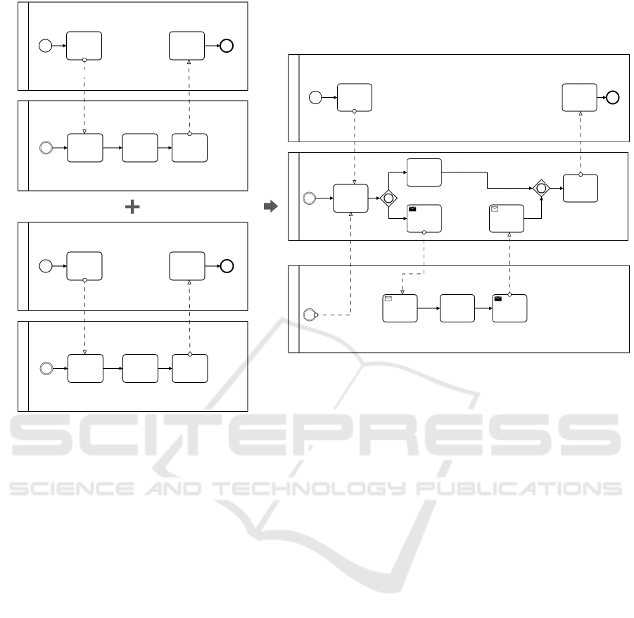
as shown in Figure 4.
3.3 Post-merge operations
Reduction
The end result of the merging can contain obsolete
behavior when merging gateway nodes. We identified
that applying reduction rules can remove the unneces-
sary gateways by inspecting whether the added gate-
ways from the merge process and the original gate-
ways have common successors. There are many pos-
sibilities for reduction since the gateway type has to
be considered. We inspected a scenario given in figure
5, which eliminates an unnecessary XOR gateway.
The process of reduction becomes more challen-
ging when gateways of different types occur. Identi-
ICEIS 2017 - 19th International Conference on Enterprise Information Systems
328

fying if a reduction is possible and its application is
part of our future research.
Send/Receive Tasks
As final step we identify if any communication bet-
ween gateways and tasks from different roles occur-
red after merging. Such behavior is not allowed in
BPMN 2.0. Therefore, we add nodes to preserve cor-
rectness in the merged model. For each such message
flow, we introduce a pair of Send and Receive tasks -
activities with limited scope that explicitly define that
a message should be sent and received respectively.
The Send Task node is placed in the same swimlane
as the node from which the message originates and
the Receive Task in the same swimlane as the reci-
pient node of the message. Instead of direct com-
munication, the message flow between gateways and
tasks from different swimlanes now happens through
the message tasks.
4 IMPLEMENTATION
The approach was implemented in Java as a standa-
lone application that takes as an input two BPMN 2.0
graphs and outputs a merged graph as result.
For creating BPMN 2.0 models, we used the Ca-
munda Open Source platform
2
. For the underlying
graph models, we used the JGraphT
3
. It also provides
an adapter to JGraph
4
, which offers elementary visu-
alizations as a Java Applet.
The merging tool provides a graph model as out-
put that serves as a reference for building the models
in Camunda. The deserialization process from the
graph model to BPMN model is done manually.
5 USE CASE: DIFFERENT ROLES
AND FLOW TYPES
We applied the approach in a use case which incor-
porates different roles. In BPMN, different roles are
represented as pools. As a consequence, we have to
consider different flow types, represented by the ed-
ges of a node. In more detail, we have to distinguish
between sequence flows and messages flows between
tasks of different roles. Figure 4 visualizes the mer-
ging output. Initially, we have three different roles:
2
https://camunda.org
3
http://jgrapht.org
4
https://jgraph.com
The user, Travel Information System (TIS) and Vehi-
cle Rental System (VRS). The role user is the same
in both input processes, because of which it can be
entirely merged. The tasks of the remaining roles are
similar, but to prevent information loss of participa-
ting roles, a messages flow points to the merged task.
Figure 5 shows the application of a reduction rule
concerning gateway operators. To reduce complexity,
we decided to replace doubled gateways and prefer-
ring the more heavily weighted gateway (in this case
XOR).
6 DISCUSSION
We investigated the suitability of matching and mer-
ging techniques in complex scenarios, considering ad-
vanced modeling constraints. Therefore, we presen-
ted a graph matching and merging approach especi-
ally intended for business processes using BPMN. We
based our work on state-of-the-art approaches, com-
bined them partially and provided solutions for open
merging problems in the specific domain. We showed
the underlying idea of considering multiple restricti-
ons, e. g. different edge types and roles and investiga-
ted the resulting effects on the merging results regar-
ding a specific use case. Moreover, our approach is
suitable to consider additional constraints as well.
At the current state of the approach, there is a li-
mited suitability in complex scenarios because here
are additional constraints that have to be considered
as well. Nevertheless, first results indicate the impor-
tance to consider advance modeling constraints. In
addition, it seems to be beneficial to have more room
for manual adjustments by the user to create useful
merging results. We showed that the consideration of
advanced modeling constraints and operations affect
the merging results fundamentally. In more detail,
considering roles and their specific modeling opera-
tors, including different flow types prevents loss of
relevant information and increases merging accuracy.
To reflect our work in more detail, we want to base
a discussion on three requirements proposed by (La
Rosa et al., 2013):
1. Behavior-Preservation describes that the behavior
of the merged model should encompass that of the
input models.
Our merging process does not change the beha-
vior of the message flow. Furthermore, the nodes
are kept within the same lanes. Additional inter-
face nodes are added to circumvent the constraints
originating from BPMN 2.0.
2. Traceability means that, given an element in the
Semi-automated Business Process Model Matching and Merging Considering Advanced Modeling Constraints
329
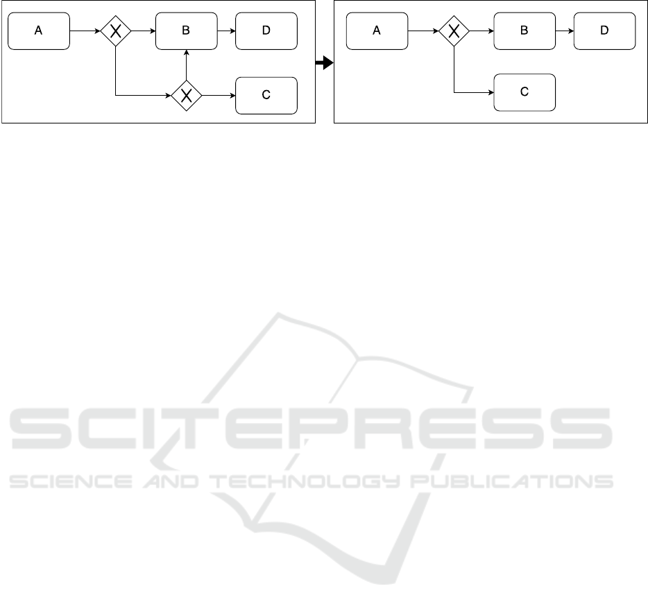
Figure 5: Applying reduction rules.
merged model, analysts should be able to trace
back the source process model from which the
element originates.
Our work achieves partial traceability: Nodes
that are inserted (gateways and interface nodes)
are assigned generated ids and behavior. Howe-
ver, there is not a clear distinction between nodes
which are specific to one model and nodes that be-
long to both of the graphs. Since merged proper-
ties take the value from G
1
, it is not clear whether
a node is specific to G
1
or for both the graphs. For
nodes specific to G
2
, that is not the case. This is
only an implementation issue which we became
of aware later in the development after the need
for traceability arose. It can be solved by storing
an additional property in each graph element that
points/references to the input model which it came
from. In case the element occurs in multiple mo-
dels, the property value can be a list of references.
3. Reversibility describes the possibility to derive the
input process models from the merged model.
Our work does not focus on reversibility. After
merging, the result model cannot be decomposed
into the original input models. Nevertheless, since
reversibility bases on traceability, once the trace-
ability feature is implemented, it would trivial to
extend the merging tool to support reversibility.
In fact, more fine-grained and precise matching
and merging approaches might have the potential to
widen the area of application and to create advanced
results for complex scenarios.
6.1 Limitations
In our initial realization we did not consider some mo-
deling operations, including for example:
• The communication between pools
• Full set of BPMN 2.0 constraints
• Advanced modeling operators, e. g. nested sub-
processes or specified sequence flows
In addition, we did not consider more than two
input graphs.
6.2 Future Work
Primarily, this approach has to be evaluated, using dif-
ferent uses cases from other domains. Hence, there
might be some room for different optimizations and
extensions, e. g. concerning the algorithm or included
operators. Further evaluation efforts should focus on
qualitative feedback from experts to estimate the suit-
ability in more detail. Especially the investigation of
the optimal degree of automation seems to be interes-
ting. Moreover, measurements concerning efficiency
issues might be valuable as well.
ACKNOWLEDGMENTS
This work was partially funded by German Federal
Ministry of Economic Affairs and Energy (BMWi)
for the project Mobility Broker (01ME12136) as well
as for the project Digitalisierte Mobilit
¨
at – Die Offene
Mobilit
¨
atsplattform (DiMo-OMP).
REFERENCES
Becker, J., Kugeler, M., and Rosemann, M. (2003). Process
Management. Springer-Verlag, Heidelberg.
Becker, J., Rosemann, M., and von Uthmann, C. (2002).
Guidelines of Business Process Modeling. Lecture
Notes in Computer Science, 1806:30–49.
Beutel, M. C., G
¨
okay, S., Kluth, W., Krempels, K.-H., Sam-
sel, C., Terwelp, C., and Wiederhold, M. (2015). He-
terogeneous Travel Information Exchange. In 2nd EAI
International Conference on Mobility in IoT (Mobili-
tyIOT 2015).
Brunet, G., Chechik, M., Easterbrook, S., Nejati, S., Niu,
N., and Sabetzadeh, M. (2006). A Manifesto for Mo-
del Merging. In GaMMa ’06 Proceedings of the 2006
international workshop on Global integrated model
management, pages 5–12, Shanghai.
Jeh, G. and Widom, J. (2002). SimRank: A Measure
of Structural-Context Similarity. In Proceedings of
the eighth ACM SIGKDD international conference on
Knowledge discovery and data mining, pages 538–
543, Admonton, Alberta.
ICEIS 2017 - 19th International Conference on Enterprise Information Systems
330

Kluth, W., Beutel, M. C., G
¨
okay, S., Krempels, K.-H., Sam-
sel, C., and Terwelp, C. (2015). IXSI - Interface for
X-Sharing Information. In 11th International Confe-
rence on Web Information Systems and Technologies
(WEBIST2015).
Kocian, C. (2011). Gesch
¨
aftsprozessmodellierung mit
BPMN 2.0. Business Process Model and Notation
im Methodenvergleich. (Business Process Modeling
using BPMN 2.0. Business Process Model and Nota-
tion in a Method Comparison). Working Paper, pages
1–32.
Kuester, J. M., Gerth, C., F
¨
orster, A., and Engels, G.
(2008). A Tool for Process Merging in Business-
Driven Development. In Proceedings of the Forum
at the CAiSE’08 conference, Montpellier, France.
La Rosa, M., Dumas, M., Uba, R., and Dijkman, R. (2013).
Business Process Model Merging: An Approach to
Business Process Consolidation. ACM Transactions
on Software Engineering and Methodology, 22(2).
Mandelin, D., Kimelman, D., and Yellin, D. (2006). A Bay-
esian Approach to Diagram Matching with Applica-
tion to Architectural Models. In ICSE, pages 222–231.
Melnik, S. (2004). Generic Model Management: Concepts
and Algorithms. LNCS, 2967.
Nejati, S., Sabetzadeh, M., Chechik, M., Easterbrook, S.,
and Zave, P. (2007). Matching and Merging of State-
charts Specifications. In ICSE 2007. 29th Internatio-
nal Conference on Software Engineering. IEEE.
Object Management Group (2016). OMG Specifications.
Semi-automated Business Process Model Matching and Merging Considering Advanced Modeling Constraints
331
