
Novel Approach of Deriving Operational Procedures for a Complex
Research Facility
Nicolae Emanuel Marinic
˘
a and Dragos¸ Dumitrescu
Horia Hulubei National Institute of Physics and Nuclear Engineering, Extreme Light Infrastructure - Nuclear Physics,
30 Reactorului, RO-077125, Bucharest-Magurele, Romania
Keywords:
Finite State Machines, Discrete Event Systems, Linear Temporal Logic, Controller Synthesis, Simulation,
Operational Procedures, MTSA.
Abstract:
Operational procedures represent a set of step-by-step actions on how to execute a complex task in which
safety plays the main role. Operational safety is employed for the protection of human operators and also of
the system components that may be very expensive and sensitive to malfunctions. Therefore, an automatic
method to generate and better understand the effects of the procedures over an entire plant is needed. For
this endeavour, each sub-system is modelled as a Finite State Process (FSP). The Modal Transition System
Analyser (MTSA) tool is used to generate and simulate a procedure for a given system behaviour and a set
of constraints. The presented plant model represents only a proof of concept and can be easily extended to
include further details of real systems.
1 INTRODUCTION
Extreme Light Infrastructure - Nuclear Physics (ELI-
NP) (Gales et al., 2016) (Ur et al., 2015), as a part
of ELI, the pan European distributed facility, aims
for producing laser-driven experiments related to nu-
clear physics. The facility, located in Magurele, Ro-
mania, will host several sub-systems used to pro-
duce the laser beam(s) (having six optical outputs),
beam transport (Ursescu et al., 2016) and experi-
ments (et.al., 2016). The facility complexity is given
by different aspects like:
• various experiments with variable flexible set-ups
must be run in parallel (as user research facility),
• future upgrades must be taken into account,
• some operations are only performed by human op-
erators,
• and, last but not least, machine and human safety
are mandatory to be considered.
Thus, the sub-systems integration followed by the
safety operation of the facility as a whole is very im-
portant.
Given the model of a complex research facility
comprising multiple interacting sub-systems and con-
straints between them, it is necessary to find the pro-
cedures to safely operate the facility such that all the
constraints are preserved. The models of each sub-
system are based on the list of requirements as de-
rived from the specifications. Each sub-system has a
local controller that takes care of the local operations
and that interacts through a limited number of signals
with the others. Sub-system interactions and regula-
tions imposed to operate such research facility gen-
erate different constraints that need to be translated
into logical conditions. The research facility has the
following components:
• HPLS - High Power Laser System;
• LBTS - Laser Beam Transport System;
• Experiment - Generic experiment using the laser
beam generated by the HPLS and transported by
LBTS systems.
The purpose of the research facility is to produce (us-
ing the HPLS) and provide (through the LBTS) to
a preselected area (represented by the Experiment)
laser beams with different characteristics for perform-
ing experiments. The entire optical path comprises
lasers, mirrors, lenses and other devices used to as-
sure the highest beam quality.
The primary aim of the paper is to show the means
to define a set of rules or procedures to safely operate
the research facility as a whole. Through modelling,
we also gain valuable insights about the caveats and
possible design extensions. Last but not least, the con-
196
Marinic
ˇ
a, N. and Dumitrescu, D.
Novel Approach of Deriving Operational Procedures for a Complex Research Facility.
DOI: 10.5220/0006396401960203
In Proceedings of the 7th International Conference on Simulation and Modeling Methodologies, Technologies and Applications (SIMULTECH 2017), pages 196-203
ISBN: 978-989-758-265-3
Copyright © 2017 by SCITEPRESS – Science and Technology Publications, Lda. All rights reserved

troller obtained based on the given constraints can be
used to implement the real control algorithm used to
supervise the plant operations. All three subsystems
are highly complex and present very expensive com-
ponents that need to be protected against any types of
human errors.
The proposed work-flow starts with the model def-
inition based on the system behaviour. Once the con-
trol objectives are established, the resulting controller,
if it exists, produces the desired system behaviour de-
fined by these objectives. The simulation of the fa-
cility model and controller locates and corrects errors
early in design system. In the current paper, we pro-
pose to use the same approach to help with the defini-
tion of procedures. The procedure definition activity
is usually done manually and is based on numerous
standards depending on the domain of activity (laser
safety, nuclear safety, etc.). The sole purpose of the
paper is to ease this process and not to replace it.
The paper is organized as follows. Section 2 pro-
vides background information on the composition of
all the sub-system models that form the plant and con-
straints. A short presentation of the theoretical frame-
work is made in Section 3. Section 4 describes an
example based on the models previously defined in
Section 2. Lastly, Section 5 draws some conclusions
about the work and presents future directions.
2 THE FACILITY MODEL
The composition of all the sub-system models (HPLS,
LBTS, and Experiment) form the plant model (further
called the environment). The system states are writ-
ten with capital letters and the transitions (actions)
between states are in italics and always start with a
small letter. The filled states represent the moments
when laser is shooting, whereas the dotted ones rep-
resent a malfunction of the sub-system. Some tran-
sitions of the sub-systems have identical labels to be
concurrently enabled.
2.1 The High Power Laser System
The actual HPLS has 2 arms and 6 outputs (3 per arm)
through which laser beams are provided at different
powers (2 x 10PW, 2 x 1PW, and 2 x 100TW). The
high power laser shot can produce severe injuries or
destroy expensive components (mirrors, lenses, etc.).
Therefore, extra precautions must be taken. Nor-
mally, the HPLS needs an internal alignment phase
before shooting and presents different safeguards im-
plemented to safely switch off the laser beam. The
shut-down process is not instantaneous and while in
the ON state, the system has no restrictions related to
the number of laser shots per experiment. There is a
low power laser beam used for alignment operations
of the optics present in the downstream sub-systems
(LBTS and Experiment). For the sake of simplicity,
the following assumptions are considered:
• only one output of the laser is available and there-
fore only one experiment will be considered,
• the internal alignment phase is neglected; thus, the
HPLS is always aligned,
• the shut-down process is instantaneous since we
do not take time into consideration,
• the alignment beam feature is as an underlying
process and therefore we do not consider it.
To model the described system, we considered a
state diagram (see Figure 1) with 5 states as follows
{IDLE, ERR, READY, ON, OFF}. The initial state
is represented by the IDLE state. The laser shoots at
full power only when in the ON state. While in the
READY or OFF states, the laser is not shooting but
all the pre-conditions to run an experiment are met.
In case of an error, the system remains indefinitely in
ERR state. An experiment starts with the expRdy and
ends by the expNxt transitions. The expFin transition
causes the HPLS to turn off the laser beam and go
to OFF state. From the OFF state, the model allows
to have multiple shoot, expFin transition sequences as
in reality (unlimited number of shots). Whereas from
ON state, a shoot transition blocks the HPLS and de-
termines transitioning to ERR state. The expNxt tran-
sition causes the HPLS to enter in IDLE state and al-
lows the user to prepare for a new experiment.
The following constraints are considered:
• a shoot transition can be only issued from the
READY and OFF states,
• at any moment a shoot, shoot, ... sequence is for-
bidden,
• if the above conditions are not fulfilled the HPLS
is blocked in an error state named ERR,
• an experiment is limited to only one shoot.
The constraints translation into logical statements and
further explanations related to the simulation lan-
guage are presented in Section 4.
2.2 The Laser Beam Transport System
The LBTS represents the interface between the HPLS
and the experiments. The core of the laser transport
part are the beam transport lines for the six main out-
puts of HPLS that contain mirrors (flat and parabolic)
of different sizes. Before each experiment set-up, the
Novel Approach of Deriving Operational Procedures for a Complex Research Facility
197

IDLE ERR
READY
ON OFF
idle
shoot
expRdy
lerror
shoot
expNxt
shooting
expFin
shoot
shoot
expNxt
Figure 1: The HPLS state diagram.
mirrors need to be aligned such that the laser beam
does not produce any damage to the LBTS compo-
nents and/or other unwanted effects. The high cost
of the mirrors and the sensitivity of beam alignment
makes this operation very important for the entire sys-
tem. The alignment is first performed in plain air fol-
lowed by the one in vacuum. During an ongoing ex-
periment the LBTS remains in vacuum. The LBTS
can become unaligned (due to external conditions)
and the entire process must be restarted.
The LBTS model is described by a state dia-
gram (see Figure 2) with 5 states as follows {IDLE,
ALAIR, ALVAC, MISAL, ON}. The initial state of
the system is IDLE. Like in the case of HPLS, the
full power beam is only present while in the ON state.
The ALAIR and ALVAC represent the states where
the LBTS is aligned in air and vacuum respectively.
While in one of these two states, if the LBTS becomes
misaligned (the MISAL state) the alignment opera-
tion must be repeated. An experiment starts with the
expRdy and ends by the expNxt transitions. The tO f f
transition marks the fact that the LBTS is not under
vacuum anymore.
To summarize, the states during which the LBTS
is under vacuum are: ALVAC, MISAL and ON. In
the case of a new experiment, the following sequence
must take place (starting from the IDLE state) as:
alAir, alVac, expRdy.
The expRdy action marks the fact that pressure be-
tween the LBTS and the interaction chamber of the
Experiment are equalized (the valves of the LBTS are
opened) and the optics path is ready for the experi-
ment.
2.3 A Generic Experiment
The experiment room contains the Interaction Cham-
ber (IC) where the experiment set-up is installed and
the rest of equipment placed outside of the chamber
itself. Normally, after a number of experiments, the
pieces of equipment found in the experimental area
but outside of the IC must be replaced or upgraded
during a maintenance phase. After a new experiment
set-up is installed, it is necessary to be aligned with
the LBTS and HPLS.
A generic experiment has three alignment phases.
The first phase is performed by using some mechan-
ical method (e.g. a theodolite) in plain air. The
next phase includes a low power laser beam from the
HPLS through LBTS (using the window gate valves).
During this phase, the LBTS must be already in the
ALVAC state. The last phase of the alignment with the
HPLS must be performed in vacuum when the gate-
valves of the LBTS are opened. Thus, during the first
two phases, the IC door is unlocked and only during
the third phase it is closed .
The Experiment is modelled by a state di-
agram (see Figure 3) with 5 states as follows
{ESETUP, EALIG, EMAINT, ERUN, EEND}.
For the sake of simplicity, we consider only one state
during which the vacuum alignment is performed (the
EALIG state) instead of considering the full align-
ment process (for example alignment with a theodo-
lite or by using the the alignment beam of the HPLS).
The maintenance phase can only be accessed from the
EALIG state or when an experiment is finished (the
EEND state). The access inside of the IC is allowed
only after the tO f f , expIcEnter transition sequence
is performed. The expSet marks the moment when the
IC access is disabled. Like in the cases of LBTS and
HPLS, the expRdy marks the fact that the experiment
can start (gate valves of LBTS are opened, the entire
experiment set-up is aligned with the LBTS and the
HPLS beam). The high power laser beam is present
only while in the ERUN state.
After an experiment, radioactive contamination
may occur and therefore the access inside of the ex-
perimental area and the interaction chamber is re-
stricted. There are a set of detectors and ultimately
a person designated to measure the radioactivity level
that allow the access inside. This feature will be in-
cluded as a future extension of the model and pre-
sented in Section 4.
SIMULTECH 2017 - 7th International Conference on Simulation and Modeling Methodologies, Technologies and Applications
198

IDLE
ALAIR
ALVAC MISAL ON
idle
alAir
alVac
alErr
expNxt
alErr
expRdy
tO f f
expNxt
shooting
Figure 2: The LBTS state diagram.
ESETU P EALIG EMAINT
ERUN EEND
idle
expSet
expIcEnt
expRdy
expMaint
idle
expIcEnt
expSet
shooting
expNxt
expMaint
expIcEnt
Figure 3: The Experiment state diagram.
3 THEORETICAL BACKGROUND
In this section, an overview of the main abstractions
used for defining the model behavior as well as the
properties it must have in order to fulfil its safety con-
siderations is presented.
Note that the following theoretical aspects
are based on the work presented in (Joslin,
2013), (D’Ippolito et al., 2011), (Keller, 1976)
and (D’Ippolito et al., 2012). Also, when referring
to complex systems, it is often useful to segregate
between the known behaviour of the system and its
desired properties. To this end, the known machine
behaviour is described as a Labelled Transition Sys-
tem (LTS) (as defined in (Keller, 1976)) under the as-
sumption of deterministic transitions between a finite
set of states, while the required system properties are
denoted as formulas in the Fluent Linear Temporal
Logic (FLTL) framework.
Definition 3.1. A LTS is a tuple S = (Σ
S
, Λ
S
, ∆
S
, σ
0
S
),
where Σ
S
is the set of all states known to the LTS, Λ
S
is the set of transition labels, ∆
S
⊂ Σ
S
×Λ
S
×Σ
S
is the
set of transitions and σ
0
S
∈ Σ
S
is the initial state.
Graphically, LTSs can be seen as graphs, where
nodes are depicted as circles, transitions are repre-
sented by arrows and transition labels are depicted by
the arrow superscripts (e.g. Figures 1, 2, 3). The ini-
tial state of the LTS is depicted by an arrow with no
start point and arriving at the given state (e.g. in figure
1, State IDLE).
Let σ
1
, σ
2
∈ Σ
S
be two states and λ ∈ Λ
S
a label.
(σ
1
, λ, σ
2
) ∈ ∆
S
can be expressed as: ”From state σ
1
,
given action λ, move to state σ
2
” and can be written
as σ
1
λ
−→ σ
2
.
The parallel composition of two LTS S
1
, S
2
, de-
noted S
1
k S
2
can be seen as the parallel execution of
the two LTS. Formally, it can be seen as the cross-
product of the state-space of the two, with a cross-
product alphabet and composition rules that mimic
name-based synchronization in case of an action hav-
ing the same name.
The parallel composition between S
HPLS
, S
LBT S
,
and S
Experiment
(further called the environment and de-
picted in Figure 4) has 36 states and 129 transitions.
As can be observed, the resulting machine exhibits a
significant amount of complexity and entails serious
strain upon human readability.
Definition 3.2. An LTS S = (Σ, Λ, ∆, σ
0
) is said to ac-
cept a sequence (trace) w = w
1
, w
2
, ... over the set Λ,
where w
i
∈ Λ if there is a trace: σ
0
w
1
σ
1
w
2
σ
2
..., with
σ
n
∈ Σ, ∀n ∈ N, such that σ
i
w
i+1
−−→ σ
i+1
∀i ∈ N.
The set of all sequences accepted by a LTS S is
denoted Gen(S).
Novel Approach of Deriving Operational Procedures for a Complex Research Facility
199
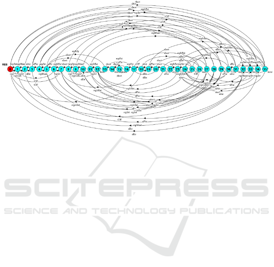
Figure 4: S
HPLS
k S
LBT S
k S
Experiment
.
As LTS is the tool for describing system behav-
ior, a different tool is required for expressing the con-
straints that must be attained for such a system. To
this end, the Fluent Linear Temporal Logic is being
employed.
In the following, the Fluent Linear Temporal
Logic constructs are defined and explained.
Definition 3.3. A fluent over a LTS S = (Σ, Λ, ∆, σ
0
) is
tuple
h
I, O, Init
i
, where I ⊂ Λ, O ⊂ Λ and Init ∈ Bool.
Informally, a fluent represents an abstract state -
or logical proposition - within the problem domain
which is enabled whenever an action λ ∈ I occurs and
is disabled whenever an action λ ∈ O occurs. Thus, a
fluent describes a logical proposition in the context of
a LTS given an input word accepted by the LTS. An
intuitive wording for a fluent f l is ”The system goes
into f l when encountering an input from the set I and
exits f l when encountering an input from the set O”.
In order to express constraints and desired out-
comes for a given composition of systems, the FLTL
formalism is employed, comprising a set of FLTL for-
mulas.
A FLTL - fluent linear temporal logic - formula is
derived from a LTL (Linear Temporal Logic) formula
(Giannakopoulou and Magee, 2003) where basic for-
mulas are in fact fluents. In LTL, formulas are either
basic formulas (predicates) or compositions of other
formulas (using logical operators or temporal opera-
tors).
Definition 3.4. A FLTL formula is given inductively:
φ , Fl | ¬φ | φ ∨ ψ | X φ| φ U ψ
Where φ, ψ are LTL formulas, Fl is a fluent from
FLTL, ¬ is the logical not operator, ∨ is the logical
or operator, X is the next operator and U is the until
operator.
Additional operators are defined based on the
aforementioned: []φ (always operator), <> φ (even-
tually operator), φ ∧ ψ (logical and operator) and
φ → ψ (φ implies ψ). Note that the always, eventually
and implies operators will be frequently employed in
solving the problem presented in the current paper.
An infinite-length word is said to always satisfy
a FLTL formula if for any suffix of the word, it still
satisfies the formula. An infinite-length word is said
to eventually satisfy a FLTL formula if there is a suffix
of the given word that satisfies the given formula. An
infinite-length word is said to satisfy a FLTL φ → ψ
if φ is satisfied only given that ψ is also fulfilled.
An infinite-length word is said to always even-
tually satisfy a FLTL formula if, for every suffix of
the given word, the formula will eventually satisfy the
formula. More intuitively, the formula will be satis-
fied infinitely many times.
For the purposes of the current paper, the informal
definitions presented above are sufficient to acquire
insights into the proposed solution. For further de-
tails, see (Joslin, 2013).
The problem of Safe Generalised Reactivity
(SGR(1)) has been thoroughly described in (Joslin,
2013). It is beyond the scope of this paper to present
the results of the aforementioned. Nevertheless, for
a better understanding, the formal definition of the
problem is provided, which will be explained briefly.
SIMULTECH 2017 - 7th International Conference on Simulation and Modeling Methodologies, Technologies and Applications
200

Definition 3.5. The SGR(1) LTS control problem is
as follows: Given a tuple ε = (E, H, A
C
) where E
is a deterministic environment described by an LTS,
A
C
is the set of controllable actions in LTS and
H =
{
(
/
0, I), (As, G)
}
, such that I = []ρ (always ρ),
As = ∧
n
i=1
([] <> φ
i
) and G = ∧
m
i=1
([] <> γ
i
), where
ρ, φ
i
, γ
i
are FLTL formulas, find a controller (LTS
machine) M with the set of actions ⊆ A
C
such that
∀π ∈ Gen(EkM),then []π I
and
∀π ∈ Gen(EkM),then π (As → G)
where ρ is called safety property, φ
i
are the assump-
tions regarding the system evolution, and ψ
i
are the
liveness properties of the system under consideration.
Thus, the SGR(1) LTS control problem is that of
finding a controller, given a behaviour of the sys-
tem and some goals. The second goal imposed in
the above definition is called liveness goal. In free
speech, it can be expressed as: knowing that the sys-
tem will fulfil several properties infinitely many times
- i.e. it will evolve -, then ensure that a set of prop-
erties are fulfilled infinitely many times when com-
posed with the generated controller. In the current pa-
per, due to the nature of the application proposed, the
safety properties will mostly be taken into account.
They can be read as: for whatever sequence of actions
that may occur in EkM (the environment controlled
by the generated controller), then the safety property
will always hold.
The problem of controller synthesis has been
solved in (Joslin, 2013). The description of inter-
nals of the algorithm that performs this specific task
is out of the scope of the current paper. Nevertheless,
a tool that offers the capabilities expressed above ex-
ists (D’Ippolito et al., 2008) and has been success-
fully used for a number of applications: controller
synthesis for a robot arm (Braberman et al., 2013) or
in automatic synthesis of behavior protocols for com-
posable web-services (Bertolino et al., 2009); (Isley,
2017) presents more case studies.
The approach to solving the problem described
within this paper was to utilize the notions of LTS
and FLTL formulas and the MTSA tool to check and
enforce several safety constraints in the depicted en-
vironment. The following section describes the ap-
proach to this end and several assumptions that aided
in the understanding and modeling of the system at
hand.
4 PRACTICAL EXAMPLE
The current framework presents a proof-of-concept of
the operational procedures design for a complex re-
search facility. Figure 5 presents the work-flow for
automatically generating a procedure. First step is
the modelling of each sub-system and its implemen-
tation as a FSP by exploiting the compositional prop-
erty used to describe the LTSs described in (Magee
and Kramer, 2006). Next step is to define the set of
constraints that can be either local or between sub-
systems.
With the help of MTSA tool, the existence of a
controller given set of constraints can be checked.
This step can have multiple iterations and may in-
clude further model modifications or refinements of
the constraints.
Models
Constraints
Database
MTSA
Controller
∃
Yes
No No
Procedure
Figure 5: Automatic Procedure Generation.
The set of allowed transitions after the parallel
composition of the controller with the environment
represents the procedure. The result automatically
satisfies the imposed constraints and can be visually
checked with the MTSA tool. Further, we present
an example based on the models defined in Sec-
tion 2. The environment can be already challeng-
ing for a human operator to find a controller that
generates a feasible trace without violating the im-
posed constraints. The set of controllable transitions
is {expRdy, shoot, expNxt, alAir, alVac, expSet,
expIcEnt, expMaint} and represents the signals that
can be enabled or disabled such that the feasible trace
is accepted. The set of imposed constraints is:
• P1 - the LBTS must be first aligned in air before
starting the experiment alignment:
fluent AF_alAir = <alAir,{alErr,expNxt}>
fluent AF_expSet =
<expSet,{expMaint,expNxt,alErr}>
Novel Approach of Deriving Operational Procedures for a Complex Research Facility
201

assert EXPALAIR = [](AF_expSet -> AF_alAir)
ltl_property P1 = EXPALAIR
• P2 - only after the experimental set-up is aligned the
alignment in vacuum is performed:
assert EXPALVAC = [](AF_alVac -> AF_expSet)
ltl_property P2 = EXPALVAC
• P3 - the entire system is declared ready for a new
experiment only after vacuum alignment was success-
ful:
fluent AF_expRdy = <expRdy,{expNxt}>
fluent AF_alVac = <alVac,{alErr, expNxt}>
assert EXPREADY = [](AF_expRdy ->AF_alVac)
ltl_property P3 = EXPREADY
• P4 - the access in the interaction chamber is allowed
only after the vacuum was removed post tO f f transi-
tion:
fluent AF_InVac = <alVac,tOff>
fluent AF_IcEnter =
<expIcEnt, expSet> initially 1
assert F_ENTERIC = [](AF_InVac -> !AF_IcEnter)
ltl_property P4 = F_ENTERIC
• NotInError - the ERR state is avoided:
fluent AF_AvoidError = <lerror,A\{lerror}>
ltl_property NotInError =
[](!(AF_AvoidError))+{A})
By running the MTSA tool, we find a 16 states
controller that allows the following feasible trace:
alAir, expSet, alVac, expRdy,
(shoot, expFin, shoot, expFin, ...),
expNxt, tO f f , expIcEnt → ...(alAir)
representing the operational procedure for running an
experiment in Experiment by using the HPLS and the
LBTS. A literal translation of the procedure can be:
Procedure 1. Running a generic experiment:
Precondition: HPLS, LBTS and Experiment in IDLE
state;
1. Align the LBTS in air (alAir transition);
2. If 1 then set-up the experiment in the IC (expSet
transition);
3. If 2 then align the LBTS in vacuum (alVac transi-
tion);
4. If 3 then start the shooting (shoot transition);
5. If experiment stops then experiment is finished
(expFin transition);
1 If experiment resumes then re-start the shooting
(go to 4);
2 Else experiment is finished;
Postcondition: After an experiment, always prepare
for the next one (expNext transition) as follows:
6. If 3 was successful then remove the vacuum (tO f f
transition);
7. Enable the access into the IC (expIcEnt transi-
tion);
Besides the current trace we can investigate other
traces to check if further constraints can be imposed.
Since the alErr transition is not controllable, it can
happen at any time. It must be observed that there
is no restriction regarding the number of shots (per-
formed experiments) or the maintenance procedure
(expMaint transition). Therefore, we added the fol-
lowing constraint:
• MAINTENANCE - after a number of shots (de-
fined by Max) it is mandatory to perform the mainte-
nance procedure:
const Max = 2 //maximum number of shoots
range Int = 0..Max
MAINTENANCE(N=0) = SHOOT[N],
SHOOT[v:Int] = (
when(v<Max) shoot->SHOOT[v+1]|
when(v==Max) {shoot,alVac}->ERROR |
when(v>0) expMaint->SHOOT[0] |
A\{expMaint,shoot}->SHOOT[v]).
• SHOOTSLIMIT - multiple shoots cycles are not
allowed:
SHOOT_ONCE = (shoot->expNxt->SHOOT_ONCE).
For the latter constraints together with the previ-
ous set, the MTSA tool produces a state machine with
67 states that represents the controller enforcing the
following behaviour:
1. an experiment cannot contain multiple shooting
sequences (shoot, shoot, ...) and,
2. there can be only Max experiments carried out in
total and,
3. the Max + 1 time, the maintenance oper-
ation must be performed by including the
expMaint transition in the execution sequence
(alVac, expSet, expMaint, expSet...)
The new procedures can be described as:
Procedure 2. Running a generic experiment:
Precondition: HPLS, LBTS and Experiment in IDLE
state;
1. Align the LBTS in air (alAir transition);
2. If 1 then set-up the experiment in the IC (expSet
transition);
3. If 2 then align the LBTS in vacuum (alVac transi-
tion);
4. If 3 then start the shooting (shoot transition);
5. If experiment stops then experiment is finished
(expFin transition);
SIMULTECH 2017 - 7th International Conference on Simulation and Modeling Methodologies, Technologies and Applications
202

Postcondition: After an experiment, always prepare
for the next one (expNext transition) as follows:
6. If 3 was successful then remove the vacuum (tO f f
transition);
7. Enable the access into the IC (expIcEnt transi-
tion);
Procedure 3. The maintenance operations
(expMaint transition) must pe performed after 2
consecutive experiments at most.
Procedure 2 is identical to 1 with the exception
that it can contain only one shoot, expFin sequence.
The latter enforces maintenance operations after a
predefined number of experiments.
5 CONCLUSIONS
The current work proposes a novel approach for de-
riving operational procedures for a complex facil-
ity where multiple sub-systems interact between each
other. The constraints can be either local (at the
sub-system level) or global (between different sub-
systems). By using the MTSA software, we can au-
tomatically generate and simulate a procedure such
that the effects of the constraints can be understood.
A high workload represents the development of the
models based on the defined requirements. Further-
more, the constraint definition may include multiple
iterations based on their effects over the entire system
(the parallel composition of all sub-systems).
Future extensions of the current work are mostly
aimed to developing the models by including more
details regarding their behaviour. However, by aug-
menting the models complexity, the constraints defi-
nition will remain the same but their number will be
increased (based on the newly introduced states and
transitions). The ultimate goal for all further devel-
opments is the complete automation of different steps
(eg. automatic alignment procedure, automatic mis-
alignment detection and correction, etc.) and the im-
plementation of the synthesised controller for the au-
tomation of the entire operational process.
ACKNOWLEDGEMENTS
We would like to thank the members of the ELI-
NP team with special thanks to Ioan D
˘
ancus¸ (for the
fruitful insights regarding the alignment process) and
Daniel Ursescu (for reviewing and his valuable re-
marks). This work is supported by the Project Ex-
treme Light Infrastructure Nuclear Physics (ELI-NP)
- Phase II, a project co-financed by the Romanian
Government and European Union through the Euro-
pean Regional Development Fund.
REFERENCES
Bertolino, A., Inverardi, P., Pelliccione, P., Pelliccione, P.,
and Tivoli, M. (2009). Automatic synthesis of behav-
ior protocols for composable web-services. In Pro-
ceedings of the the 7th Joint Meeting of the European
Software Engineering Conference and the ACM SIG-
SOFT Symposium on The Foundations of Software En-
gineering, pages 141 – 150.
Braberman, V., D’Ippolito, N., Piterman, N., Sykes, D., and
Uchitel, S. (2013). Controller synthesis: From mod-
elling to enactment. In Proceedings of the 2013 Inter-
national Conference on Software Engineering, pages
1347 – 1350.
D’Ippolito, N., Braberman, V., Piterman, N., and Uchitel, S.
(2011). Synthesis of live behaviour models for fallible
domains. In 2011 33rd International Conference on
Software Engineering (ICSE), pages 211–220.
D’Ippolito, N., Braberman, V., Piterman, N., and Uchitel, S.
(2012). The Modal Transition System Control Prob-
lem, pages 155–170. Springer Berlin Heidelberg.
D’Ippolito, N., Fischbein, D., Chechik, M., and Uchitel, S.
(2008). Mtsa: The modal transition system analyser.
In 2008 23rd IEEE/ACM International Conference on
Automated Software Engineering, pages 475–476.
et.al., F. N. (2016). Laser driven nuclear physics at elinp.
Romanian Reports in Physics, 68:S37S144.
Gales, S., Balabanski, D. L., Negoita, F., Tesileanu, O., Ur,
C. A., Ursescu, D., and Zamfir, N. V. (2016). New
frontiers in nuclear physics with high-power lasers
and brilliant monochromatic gamma beams. Physica
Scripta, 91(9):093004.
Giannakopoulou, D. and Magee, J. (2003). Fluent model
checking for event-based systems. SIGSOFT Software
Engineering Notes, 28(5):257–266.
Isley, P. (2017). The modal transition system analyser.
http://mtsa.dc.uba.ar/.
Joslin, P. (2013). Synthesis of event-based controllers for
software engineering. PhD thesis, Imperial College
London.
Keller, R. M. (1976). Formal verification of parallel pro-
grams. Commun. ACM, 19(7):371 – 384.
Magee, J. and Kramer, J. (2006). Concurrency: State Mod-
els and Java Programs. Wiley Publishing, 2nd edition.
Ur, C., Balabanski, D., Cata-Danil, G., Gales, S., Morjan,
I., Tesileanu, O., Ursescu, D., Ursu, I., and Zamfir, N.
(2015). The elinp facility for nuclear physics. Nuclear
Instruments and Methods in Physics Research Sec-
tion B: Beam Interactions with Materials and Atoms,
355(9):198 – 202.
Ursescu, D., Cheriaux, G., Audebert, P., Kalashnikov, M.,
Toncian, T., Cerchez, M., Kaluza, M., Paulus, G.,
Priebe, G., Dabu, R., Cernaianu, M., Dinescu, M.,
Asavei, T., Dancus, I., Neagu, L., Boianu, A., Hooker,
C., Barty, C., and Haefner, C. (2016). Laser beam de-
livery at eli-np. Romanian Reports in Physics, 68:S11
S36.
Novel Approach of Deriving Operational Procedures for a Complex Research Facility
203
