
Towards Teleoperation and Automatic Control Features of an
Unmanned Surface Vessel-ROV System: Preliminary Results
L. Nava-Balanzar
1
, J. L. Sanchez-Gaytán
1
, F. Fonseca-Navarro
1
, T. Salgado-Jimenez
1
,
M. Á. Reyna-Alonso
2
, L. G. Garcia-Valdovinos
1
, O. Rubio-Lopez
1
,
A. Gómez-Espinosa
2
and A. Ramirez-Martinez
1
1
Center for Engineering and Industrial Development - CIDESI, Energy Division, Querétaro, Mexico
2
Tecnológico de Monterrey, Campus Querétaro, Querétaro, Mexico
Keywords: Unmanned Surface Vessels (USV), ROV, USV-ROV System and Auto Tuned PID.
Abstract: This paper presents the design, construction and control of an Unmanned Surface Vessel (USV) along with a
ROV (Remotely Operated Vehicle) system, called USV-ROV system. These systems are mainly used for
underwater inspection of shallow water structures, such as: ports, bridges bases and platforms. The USV-
ROV, developed at CIDESI-Mexico, has been designed for academic purposes. This paper describes the
Surface Control Unit (SCU), the ROV and the USV, including: electronics architecture, data managing,
sensors, actuators and mechanical design considerations. USV and ROV control strategies preliminary results
are presented. Real time experiments are shown for: USV heading control, and ROV depth and heading
control. The goal of this paper is to present preliminary results of a coordinated USV-ROV system, desgined
for the development of inspection and surveillance techniques accroding to the marine and submarine
application; however, these techniques are not commercially available and have to be developed with an open
architecture system like the presented here.
1 INTRODUCTION
Unmanned Surface Vessels (USV) and Remotely
Operated underwater Vehicles (ROV) are widely
used by academic laboratories, corporations and
governments. Some examples of USV and
applications are mentioned in (Manley, 2008), (V.
Bertram, 2005). The USV-ROV systems are the
improvement of the USVs, motivated by the
applications, such as inspection of ports, bridge bases
and platforms, etc. (Vladimir, 2010), (Healey, 2007).
Some examples of commercial USV-ROV systems
are: (1), (2) and (3).
In this paper an academic USV-ROV System
designed at CIDESI-Mexico is described. The section
II details: the Surface Control Unit (SCU), the ROV
(Remotely Operated Vehicle) and the Unmanned
Surface Vessels (USV), including: electronic
architecture, data managing, sensors, actuators and
mechanical considerations. Section III explains the
control techniques used to control the USV - ROV
system. Real time experiments are presented to show:
the heading control for the vessel, and depth and
heading control for the ROV. Finally, the section IV
discloses conclusions and future work.
2 USV-ROV SYSTEM
DESCRIPTION
This paper describes the development of a small-sized
underwater vehicle ROV deployed by an
instrumented USV. Some real applications of the
USV-ROV system are: marine survey and USV-
ROV collaborative work. The general architecture,
shown in Figure 1, consists of three main parts: The
Surface Control Unit (SCU), a tele-operated Vessel
and a ROV. These systems, including their
mechanical design considerations are described in
this section.
292
Nava-Balanzar, L., Sanchez-Gaytán, J., Fonseca-Navarro, F., Salgado-Jiménez, T., Reyna-Alonso, M., Garcia-Valdovinos, L., Rubio-Lopez, O., Gómez-Espinosa, A. and Ramirez-Martinez,
A.
Towards Teleoperation and Automatic Control Features of an Unmanned Surface Vessel-ROV System: Preliminary Results.
DOI: 10.5220/0006414302920299
In Proceedings of the 14th International Conference on Informatics in Control, Automation and Robotics (ICINCO 2017) - Volume 2, pages 292-299
ISBN: Not Available
Copyright © 2017 by SCITEPRESS – Science and Technology Publications, Lda. All rights reserved
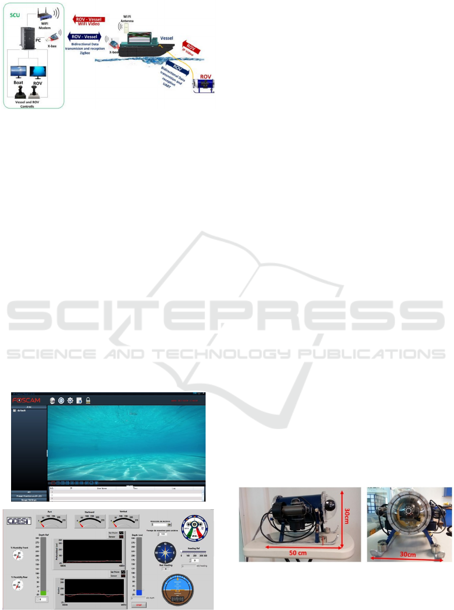
Figure 1: USV – ROV system.
2.1 Surface Control Unit
The SCU is the conjunction of the hardware (WiFi
modem, PC, XBee, Joysticks, Keyboard, etc) and the
software like the IP camera viewer and the Human
Machine Interface (HMI) that generates the
commands to perform a specific task. Additionally,
the SCU receives the status of the vehicles in real
time. The SCU is based on a computer that hosts the
HMI which is programmed in LabVIEW software,
where the data, status and images of both vehicles are
displayed. All the data and commands generated from
and to the vehicles are received and sent in real time
by a RF Xbee radio transmitter/receiver which uses
Zigbee protocol.
The SCU has two joysticks to command the
vehicles, one for the Surface Vessel and another one
for the ROV. The video transmission of the cameras
(one at the vessel and one at the ROV) is performed
by a dedicated WiFi communication channel. Figure
2 shows the Human Machine Interface (HMI).
Figure 2: Human Machine Interface.
• Data Managing: Both vehicles have a main
processing data board, which will be described
later in the sections ROV description and Vessel
description, these boards are responsible for
managing the data sent from the SCU to each
vehicle. The way that the data is sent is simple:
data frames are generated by the LabVIEW
program. Those frames contain values like:
thruster speed (for each thruster), thrust
direction (for each thruster) and others digital
functions, separated by commas. It’s important
to know that both vehicles have their own data
frame that is sent from the SCU by a serial port.
When the frames are received by the appropriate
vehicle each main board separates every data,
assigning it a value that generates a specific
output signal for each actuator. Backwards,
sensors data frames are generated by the main
boards of the vehicles, and sent via serial port to
the SCU, where they are classified and separated
to be displayed in their correct position.
2.2 ROV Description
The underwater vehicle is a small-sized ROV, named
Nu’ukul Ha (which in Mexican Mayan language
means “water instrument”). Its dimensions are: 50 cm
long, 30 cm wide and 30 cm height; as shown in
Figure 3. It has a cylindrical pressure chamber of 15
cm in diameter, where the major part of the electronic
architecture is placed. The total weight of the ROV is
10 kg. The electronic architecture of the ROV (shown
in Figure 3) was placed in a plastic 3D printed rack.
This architecture is divided into three groups:
instrumentation, signal and data acquisition, and
actuators. The instrumentation involves: pressure
sensor, leakage sensors, IMU (Inertial Measurement
Unit), voltage and electric current sensors.
The electronic architecture is managed by a
microcontroller (main board). Finally, the actuators
consist of four thrusters used to provide direction and
Figure 3: ROV Nu' ukul Ja (“water instrument” in Mexican
Mayan language). This ROV is connected to the boat by a
tether, which has twelve wires: eight are used to receive
video from the IP camera, two for the power connections
(24V and Ground) and four for the data UART transmission
(TX)/reception (RX).
Towards Teleoperation and Automatic Control Features of an Unmanned Surface Vessel-ROV System: Preliminary Results
293
displacement to the ROV, and an IP camera for
inspection missions.
Figure 4: ROV’s electronic architecture Diagram.
• Instrumentation: This ROV has a MS5837-
30BA pressure sensor which is placed outside
the pressure chamber of the submarine. This
sensor is a high resolution barometer which
obtains data of the surrounding hydrostatic
pressure. Once the hydrostatic pressure is
obtained the depth level is calculated by: ℎ=
, where ℎ= depth [m], = hydrostatic
pressure [mbar],
= atmospheric pressure
[mbar], = water density
and =
acceleration of gravity
.
In order to measure 3 DOF (degrees of freedom)
of the ROV (pitch, yaw and roll), a TCM-MB IMU is
used. The TCM sends hexadecimal serial packages
with a frequency up to 30 Hz. To prevent malfunction
of the electronics due to water presence, leakage
sensors are used. Besides, a voltage sensor (5 to 1 Vdc
divider) offers analog signal of voltage of the
batteries. A Hall effect current sensor (Pololu AC715)
measures the current consumption of the vehicle,
while the current sensors embedded in the motor
driver (Pololu VNH5019) allows to monitor the
operation of the thrusters.
• Signal and Data Acquisition: Inside the
pressure chamber of the submarine is located a
SAM3X8E ARM Cortex embedded in the
Arduino Due board. It has 54 general purpose
inputs and outputs, 12 of them PWMs, 12 analog
inputs, 4 UART ports and one I2C bus. This
board is used to manage communication
between the user and the small-sized ROV.
• Actuators: As mentioned previously, to control
the submarine in the horizontal plane, two
brushed SeaBotix BTD150 thrusters are placed
horizontally on each side of the underwater
robot. Two more BTD150 thrusters are placed
vertically on each side of the ROV to sink the
vehicle at will (Robert D, 2014), (see Figure 5).
The BTD150 thrusters are powered by 20
VDC@ 4 A.
• ROV Mechanical Considerations: The
mechanical considerations for the ROV design
were: small-sized remotely operated vehicle (50
cm long, 30 cm wide and 30 cm height),
maximum working depth 10 m. Additionally,
the ROV has a convenient shape to be launched
and recovered by the remotely controlled vessel
by using a LARS (Launch and Recovery
System). The Figure 5 shows some CAD views.
By using CAD the center of gravity and center
of buoyancy were calculated, and a structural
analysis was performed.
(5.a)
(5.b)
Figure 5: ROV’s frontal view (5.a) and lateral view (5.b).
2.3 Unmanned Surface Vessel (USV)
The instrumented vessel was developed at CIDESI.
Its dimensions are: 204 cm long, 137.5 cm wide, and
92 cm height (Figure 6). It has two floats: one has the
rack with the electronic architecture and the second
the batteries. Both floats have humidity sensors for
leak detection. The electronic architecture is shown in
figure 7, it is divided into three groups: instrumenta-
tion, signals and data acquisition, and actuators. The
instrumentation includes the following devices:
ICINCO 2017 - 14th International Conference on Informatics in Control, Automation and Robotics
294
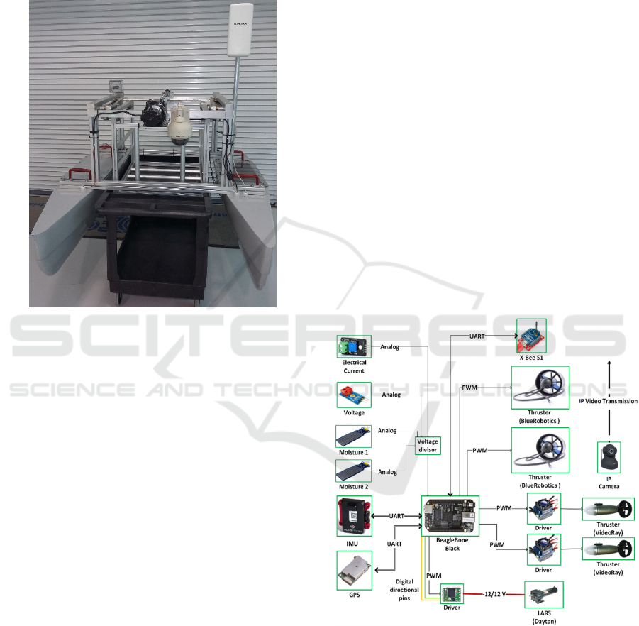
current, voltage and humidity sensors, IMU and GPS.
A BeagleBone Black computer is used to manage the
signal and data acquisition. Finally, the actuators
consist of four thrusters to provide direction and
displacement to the vehicle, and an IP camera is used
for surface inspections.
Figure 6: USV developed at CIDESI, mounted in a carriage
for ground transportation.
The communication SCU - Vessel is wireless
(Xbee cards) by using the UART peripheral, while the
wired communication Vessel - ROV uses another
UART peripheral. The vessel power supply is 24
Vdc.
• Instrumentation: The Surface Vessel, is a
mothership vehicle that carries the ROV, which
has data reception functions, a camera, while the
instrumentation has the following sensors:
Current Sensor: to monitor vehicle’s electrical
current consumption. Pololu ACS714 is a linear
sensor with a resolution of 0.066 V/A. Voltage
sensor: to measure the power supply. It is B25 analog
device with a resolution of 0.00489 Vdc. Two
humidity sensors: to detect water leakage, the high
sensitivity water sensors have an analog interface
with an output voltage signal of 0~4.2 Vdc. Inertial
sensor: to determine the Euler angles of the vehicle
(roll, pitch and yaw), (Robert D, 2014) the AHRS
DC-4EP Sparton device is used; this sends NMEA
serial packages or Euler angles only with a frequency
of 10 Hz. GPS 15xl-w Garmin device: for global
location of the Surface Vessel, this sends NMEA
serial packages with acquisition time less than 2
seconds.
The current, voltage and humidity sensors are analog
devices; these are connected to a voltage divisor
because the analog inputs of the BeagleBone Black
are 3.3 Vdc, while the AHRS and GPS are connected
to UART peripherals.
• Signal and Data Acquisition: A BeagleBone
Black development board is used for signal and
data acquisition, which has the following
specifications: a Sitara ARM Cortex-A8
processor running at 1000 MHz, 512 MB of
RAM, 4 UART ports, 8 PWM signals, 2 SPI
ports, 2 I2C ports, 7 A/D Converters, 2 CAN
bus, 4 Timers and a consumption of 210–460
mA, programmed with the software Eclipse IDE
Development (version Mars 2.0).
• Actuators: Two brushless motors VideoRay
with a Pololu’s VNH5019 driver at rear for
forward and reverse motion, they are powered
by 12Vdc and maximum current to 17 A. Two
brushless motors BlueRobotics for lateral
motion, the T100 Thruster are powered by
12Vdc and maximum current to 11.5 A. One
Permanent Magnet DC motor Dayton for the
LARS motion, it is powered by 12Vdc and 1/8
HP.
Figure 7: Vessel electronics Architecture Diagram.
• Vessel Mechanical Design: The mechanical
considerations for the vessel design were: The
boat is used for the surveillance in collaboration
with a ROV. The main task of the vessel is to
transport, launch and recover a small sized
ROV. The Figure 8 shows some views from the
CAD. A LARS is used to launch the underwater
Towards Teleoperation and Automatic Control Features of an Unmanned Surface Vessel-ROV System: Preliminary Results
295
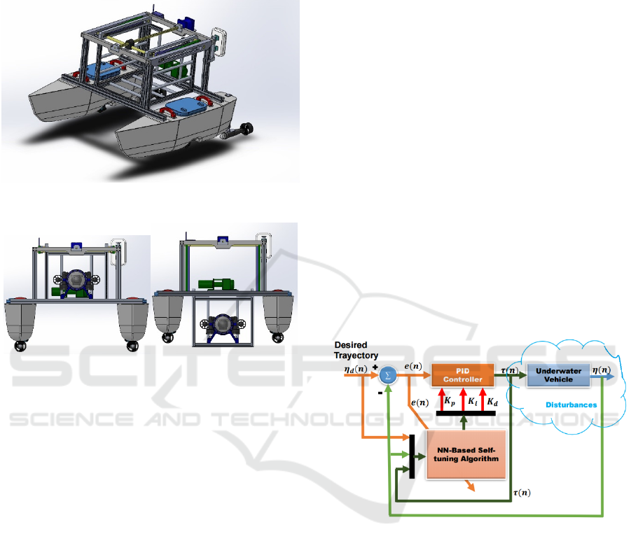
vehicle into the water and to recover it, without
direct human intervention. Figure 9 shows
LARS transportation position (top) and launch
and recovery position (bottom).
Figure 8: Vessel isometric view.
Figure 9: LARS (Launch and Recovery System). LARS
transportation position (left) and launch and recovery
position (right).
2.4 USV-ROV System Control
The USV-ROV system has two modes of control:
teleoperation and automatic control. In this section,
the implemented automatic control are explained.
Two control algorithms were implemented: a
conventional PID and an auto-tuned PID. The
controllers were tested in a set of real time
experiments.
2.4.1 PID Control
The PID controller is well known and widely used in
the industry and robotics to improve the dynamic
response of a system as well as to reduce or eliminate
the steady state error. PID control consists of three
types of control: Proportional, Integral, and
Derivative control. The tuning of PID controllers
depends on adjusting its gains (
,
,
) so that the
performance of the system under control becomes
robust and accurate according to the established
performance criteria. In the discrete time domain, the
digital PID algorithm can be expressed as follows
(10):
τ(n)=τ(n-1)+K_p (e(n)-e(n-1))+K_i e(n)+
K_d (e(n)-2e(n-1)+e(n-2)) (1)
where τ(n) is the original control signal,
=
− represents the position tracking error,
denotes the desired trajectory,
is the proportional
gain,
the integral gain,
the derivative gain, and
n-the sample time. This controller was applied to
heading control (ψ) in both vehicles: ROV and
Vessel.
2.4.2 Auto Tuned PID Control
In order to control the depth (z) of the ROV, an auto-
tuned PID controller based on an online Neural
Network (NN) was implemented. The purpose of
having an auto tuned depth control, was to allow the
vehicle to be modular, which means, makes the ROV
capable of adding or changing tools or different kinds
of instrumentation depending the mission to be
performed, avoiding the necessity to re-adjust the
control parameters.
A block diagram of the auto-tuning control with
an artificial neural network (NN) is shown in figure
10.
Figure 10: Auto-tuned PID control block diagram (8).
The algorithm used as auto-tuning is the
backpropagation method, chosen for its ability to
adapt to changing environments. The back-
propagation algorithm looks for the minimum of the
error function in weight space using the method of
gradient descent (D. Maalouf, 2013), (Hernández,
2016). The combination of weights which minimizes
the error function is considered to be a solution of the
learning problem.
The NN has seven neurons in the input layer, three
neurons on the hidden layer and three on the output
layer. The neurons placed on the output layer
correspond to the PID gains:
,
and
. The PID
algorithm used in the automatic tuning control is the
same as that presented in equation (1).
ICINCO 2017 - 14th International Conference on Informatics in Control, Automation and Robotics
296
3 USV AND ROV REAL TIME
EXPERIMENTS
This sub-section describes the heading control for the
vessel and the ROV. The pilot defines heading set
points in degrees referenced to the magnetic North.
These set points are sent to the Vessel and the ROV,
the automatics controls algorithms cause the two
vehicles headed to the same direction. The way that
the ROV and the boat change the heading is spinning
in opposite direction their lateral thrusters, generating
in this way a moment of torque with respect the center
of gravity of each vehicle.
3.1 Experiment Description
The procedure to perform the experiment is:
1) Locating the ROV at 1 m of depth by an auto
tuned PID, a set point of 110 ° heading is sent to
the ROV and the Vessel.
2) Once both vehicles are stable in the reference,
the experiment starts recording samples of:
actual heading, set points and output control
signals every 100 ms by 2 minutes.
3) After two minutes and without stop the
sampling, a reference of 45° is sent to the
vehicles for another two minutes.
4) Then, the set point is changed to 80° for 2
minutes.
5) Finally, the reference is changed to 180° for the
last two minutes.
6) The sampling time is 100 ms.
3.2 USV and ROV Heading Control:
Experimental Results
Following the procedure mentioned above, the PID
controllers for the vessel and the ROV were tested. In
the figure 11, graphs of the heading behavior are show.
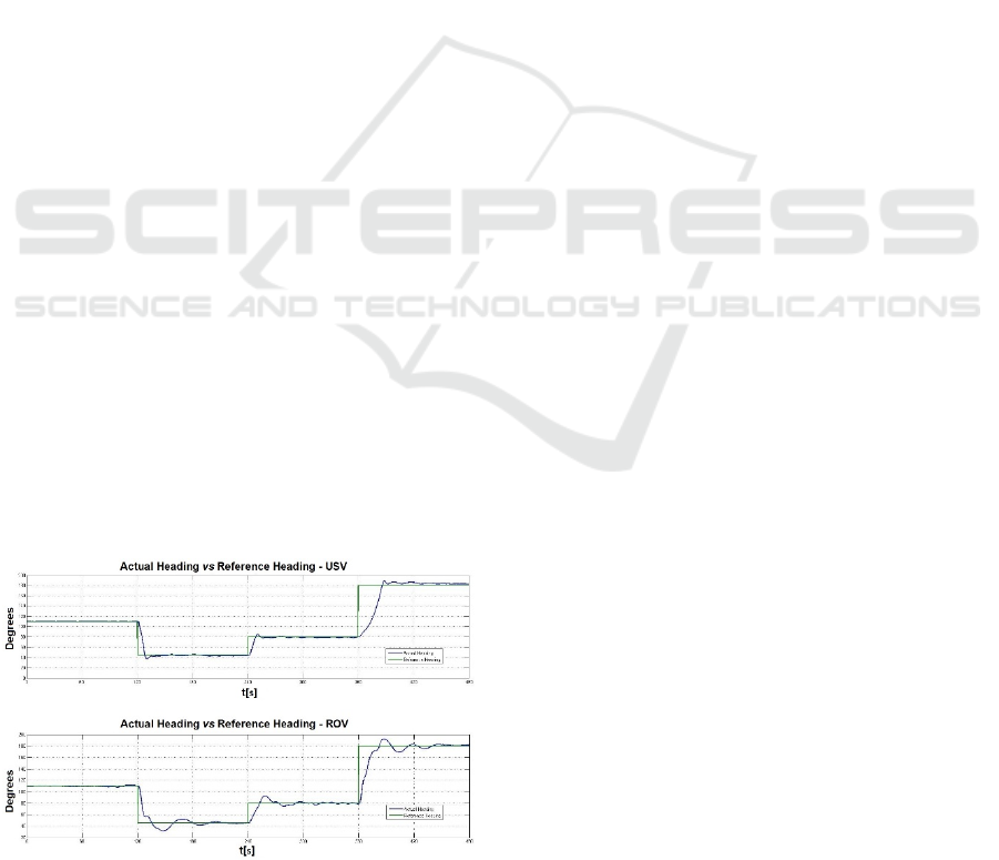
Figure 11: Heading vs time behavior for the vessel (above)
and the ROV (bottom).
Figure 11 shows that the vehicles have about the same
behavior when they are exposed to the same reference
signal. It is important that the vehicles have an
identical heading, which would be useful when they
are carrying out a structural inspection. The Root of
the Mean Squared value (RMS) was obtained for the
experiments. The vessel has 17.787 degrees and ROV
has 13.134 degrees.
3.3 ROV Depth Control
As detailed above: Throughout the heading
experiments the ROV depth reference point was 1 m.
The implemented controls were: PID and auto-tuned
PID.
These controls were evaluated by performing a
three-minute test with the following characteristics
(phases):
Phase 1:
- The ROV is placed at 1 m depth.
- Not disturbance was given to the ROV during
the first minute.
Phase 2:
- During the second minute, a 400 g lead weight
was placed on the top of the ROV.
Phase 3:
- Finally, at the third minute the weight was
removed, making the parameters of the vehicle
be exactly the same as when the experiment
was started.
The gains of the conventional PID control were
obtained by means of the NN. The ROV was
requested to get the set point of 1 m depth by using
the Auto-tuned PID controller. Once the ROV
reached the stability and the control gains computed
by the NN became stationary, these gains were
programmed into the conventional PID. It is
important to remark that once the conventional PID
was tuned, the gains remained constant along the
experiment, even when the disturbances took place.
The graphs obtained by this experiment divided
by its three phases are the ones shown in the figure
12, comparing the reference (blue) and the actual
depth (red) of the ROV during the experiment. Figure
12.a conventional PID control and figure 12,b auto-
tuned PID control.
Towards Teleoperation and Automatic Control Features of an Unmanned Surface Vessel-ROV System: Preliminary Results
297
(12.a)
(12.b)
Figure 12: Depth control. Conventional PID Controller
(12.a). Auto-tune PID (12.b).
The Root Mean Square Error (RMSE) is computed in
each experiment; A 3.51 cm error is obtained for the
conventional PID, while a 2.47 cm error is obtained
for the self-adjusted PID.
The RMSE of three phases was obtained and it is
shown in figure 13. It is important to note: the
conventional PID presents the biggest error in the
second phase (when the weight is added), proving the
need of re-tuning the PID gains.
Figure 13: RMSE of both experiments (convwnbtional PID
and auto-tuned PID) for each phase.
4 CONCLUSION
The development of an academic USV – ROV system
was presented, including electronic, data trans-
mission and mechanical considerations. Preliminary
control results are presented, towards automatic
collaborative techniques.
This USV – ROV system was designed thinking
in the application of inspection and surveillance of
marine and submarine structures. The main
contribution of this work is the collaborative USV –
ROV techniques considering a low cost - open
architecture system.
Future Work:
• Improve collaborative USV - ROV control
techniques.
• USV-ROV system field test.
• Suggest improvements to develop the inspection
of oil platforms in Mexican waters.
ACKNOWLEDGEMENT
Research supported by CONACYT projects:
PDCPN2013-01-215770.
This study is part of the project number 201441
“Implementation of oceanographic observation
networks (physical, geochemical, ecological) for
generating scenarios of possible contingencies related
to the exploration and production of hydrocarbons in
the deepwater Gulf of Mexico”, granted by SENER-
CONACyT Hydrocarbons Sectorial Fund.
ICINCO 2017 - 14th International Conference on Informatics in Control, Automation and Robotics
298

REFERENCES
Subsea Tech, Cat – Surveyor. (http://www.subsea-tech.com)
Marine Tech, RSV Sea Observer. (http://en.marinetech.fr/)
Thales-SAAB Seaeye, Halcyon USV & Falcon Remotely
Operated Vehicle (ROV). (https://www.thalesgroup.
com/)
J. Manley, “Unmanned Surface Vehicles, 15 Years of
Development”, Proc. MTS/IEEE Oceans’08
Conference, Québec, 2008.
V. Bertram, “Unmanned Surface Vehicles – A Survey”,
IEEE Standard for Application and Management of the
Systems Engineering Process, IEEE Std 1220-2005,
September 2005.
Vladimir Djapic and Dula Nad. “Using collaborative
autonomous vehicles in mine countermeasures”. Proc.
MTS/IEEE OCEANS’10, Sydney 24-27 May 2010.
Healey, Anthony J., Horner, D. P., Kragelund et al.
“Collaborative unmanned systems for maritime and
port security operations”. 7th IFAC Conference on
Control Applications in Marine Systems. 2007.
Robert D. Christ and Robert L. Wernli Sr., “The ROV
Manual”, Second Edition, Elsevier, 2014.
Fossen, T. I. “Guidance and Control of Ocean Vehicles”,
John Wiley & Sons, 1994.
Katsuhiko Ogata. “Discrete-Time Control Systems”,
Prentice Hall. Edición 2. 1995.
D. Maalouf, I. Tamanaja, E. Campos, A. Chemori, and V.
Creuze, “From PD to Nonlinear Adaptive Depth-
Control of a Tethered Autonomous Underwater
Vehicle,” 5th IFAC Symposium on System Structure
and Control, Volume 46, Issue 2, Pages 743-748,
Elsevier, 2013.
Hernández-Alvarado R., García-Valdovinos L. G.,
Salgado-Jiménez T., Gómez-Espinosa A. and Fonseca-
Navarro F., Neural Network-Based Self-Tuning PID
Control for Underwater Vehicles. Sensors (Basel).
2016 Sep 5; 16(9). 2016.
Towards Teleoperation and Automatic Control Features of an Unmanned Surface Vessel-ROV System: Preliminary Results
299
