
An Automated Quadcopter CAD based Design and Modeling Platform
using Solidworks API and Smart Dynamic Assembly
Mohammad Shaqura
1
and Jeff S. Shamma
2
1
Mechanical Engineering, Physical Science and Engineering, King Abdullah University of Science and Technology,
Thuwal, Saudi Arabia
2
Electrical Engineering, Computer, Electrical and Mathematical Sciences and Engineering,
King Abdullah University of Science and Technology, Thuwal, Saudi Arabia
Keywords:
Multirotor Robots, UAV, CAD Modeling, API, Dynamic Assembly, Flight Simulation.
Abstract:
Multirotors micro aerial vehicles (UAV) have become a standard platform in robotics and control research
related to algorithmic development as well as design innovation. Custom-built designs based on open-source
architecture and off-the-shelf components are attractive for researchers due to low cost and easy rapid pro-
totyping. Hardware selection and integration is usually based on heuristics. Building a realistic quadcopter
simulator requires accurate modeling and knowledge of its dynamics and the effect of each component on
that. Often, moving from simulation to actual experiment is a challenging task due to the huge dynamical
differences when working with the real system. The presented work aims to strengthen the bridge between
simulations and actual system through an automated CAD based modeling software system that generates re-
alistic models mathematically and visually for Matlab Simscape physics simulation and visualization utilizing
Solidworks API, smart mating techniques and dynamical analysis. A proof of concept application with user
friendly interface is built for Windows OS and the system components are further illustrated.
1 INTRODUCTION
Quadcopters have become popular testbeds in control
research due to their high maneuverability and ability
to execute complex motion patterns. This agility is re-
sulted from the large torques about the center of mass
caused by the propulsion forces away from the center.
Although several robust quadcopter systems are avail-
able in the market, most do not meet the autonomous
research needs, flexibility and modularity required for
development. Researchers often choose to build their
own quadcopter systems using off-the-shelf compo-
nents and open-source flight controllers. This allows
full access to hardware/software interfaces and con-
trol/estimation functions.
Testing high-level control algorithms such as au-
tonomous navigation, optimal coverage, multi-agent
control and mapping requires low level control sta-
bility meaning that the vehicle should achieve good
performance in hover and attitude control which re-
sults in better velocity and position control. If one
choose custom hardware building, the selection op-
tions of components is limitless and usually this is
done based on heuristics, suggestions and best guess.
Several generic quadcoptors simulation toolboxes
are available across multiple platforms. (Corke, 1996)
Usually, a simplified quadcopter model is utilized
with minimum geometrical and dynamical details. A
good knowledge of the model is assumed to be known
by the user and it is added as an input in the form
of a configuration or model structure file. The simu-
lation results is as good as the model describing the
actual system. Physical simulators, such as Matlab
Simscape, V-Rep and Gazebo, provide powerful real-
istic results through simulating the modeled individ-
ual components of the system. (Rohmer, 2013), (The
MathWorks Inc., 2016), (Koenig, 2004), (Meyer,
2012). The physics engine solver simulates the be-
havior of the system under components uncertainty
(sensors/actuators noise) and external forces. Users
of these simulators face two challenges, the high com-
putational and graphical requirements needed and the
hectic modeling, design and redesign task which usu-
ally require good expertise in Computer Aided Design
software tools. The first challenge is being attenuated
with the accelerated advancement in computer hard-
ware that made running some physical simulation en-
gine possible on a personal computer.
Prior to creating a realistic quadcopter simulation,
one need to acquire enough knowledge about the ge-
122
Shaqura, M. and Shamma, J.
An Automated Quadcopter CAD based Design and Modeling Platform using Solidworks API and Smart Dynamic Assembly.
DOI: 10.5220/0006438601220131
In Proceedings of the 14th International Conference on Informatics in Control, Automation and Robotics (ICINCO 2017) - Volume 2, pages 122-131
ISBN: Not Available
Copyright © 2017 by SCITEPRESS – Science and Technology Publications, Lda. All rights reserved

ometrical and aerodynamical effects. This includes
mass and inertial properties, thrust and power systems
modeling. These are classically determined through
mechanical assessment to measure thrust created by
each rotor, center of gravity (COG) with respect to
the vehicle center, total mass and individual compo-
nent mass and the inertia tensor(Domingues, 2009).
Different approaches have been applied to simplify
the modeling task and determine an easily controlled
model representation of the quadcopter system. This
can be in the form of linear approximation, experi-
mental data driven models or online model parameter
identification using deterministic and stochastic esti-
mation techniques (Sa, 2012).
Modern Computer Aided Design (CAD) tools are
packed with tremendous engineering capabilities be-
yond the 3D design default functionality. Solidworks
for instance offer powerful engineering tools for de-
sign, modeling and analysis such as flow simulation
with embedded CFD solvers and motion assessment
(Zhang, 2014), (Kuantama, 2017).
In this work, a system to automate the quad-
copter design, modeling and simulation is developed
in the form of user friendly interface. The tool is
developed based on the Solidworks Application Pro-
gram Interface (API) and Matlab Simscape toolbox
for model validation, simulation and control devel-
opment. Solidworks API allow developers to cre-
ate a standalone applications that utilized its engi-
neering capabilities. Using this interface, the user
specifies the quadcopter frame and components specs
including material, weight, dimensions and location
or choose from the library of commercially available
products. The software uses the provided specifica-
tions to generate the 3D model, identify its parameters
and the Matlab simulation environment files. In the
next section, the quadcopter equation of motions and
model parameters are presented. Then, the compact
component representation is discussed and how smart
mating works in an automated environment. In sec-
tion 4, general overview of the software tool use and
functionality is presented. Then, the article is con-
cluded with opportunities and future directions of this
project.
2 QUADCOPTER DYNAMICAL
MODEL
The quadrotor model is a 12 states nonlinear model,
x,y, z denotes position, v
x
,v
y
,v
z
denote the velocities,
φ,θ,ψ denote the roll, pitch and yaw attitude angles
respectively, ω
x
,ω
y
,ω
z
denote the rotational veloci-
ties. When presenting the quadrotors dynamics, one
should define a reference frame or known as inertial
frame where the states of the system are evolving with
respect to that reference. The actuation mechanism
(propulsion) in quadrotors acts directly on the body
frame, to illustrate this, the z-axis coincides with the
line pointing outward from the center of the quadro-
tors regardless of the orientation. In the inertial refer-
ence frame, the z-axis is fixed and present the altitude
of the quadrotors from a reference plane, e.g. ground.
Entities in the body frame should be transformed to
the inertial frame through a rotational matrix that is a
nonlinear function of the attitude angles. Let A and
B denote the inertial and body frames respectively, to
transform a vector from B to A, it is multiplied by the
rotational matrix:
R
A
B
=
cψcθ − sφsψsθ −cφsψ cψsθ+ cθsψsφ
cθsψ + cψsθsφ cφcψ sψsθ− cψcθsφ
−cφsθ sφ cφcθ
(1)
where c denotes the cosine function and s the sine
function. The dynamical model of forces and mo-
ments can be written as:
m
¨r
x
¨r
y
¨r
z
−
0
0
mg
= R
A
B
F
x
F
y
F
z
(2)
J
˙
ω
x
˙
ω
y
˙
ω
z
+
ω
x
ω
y
ω
z
× J
ω
x
ω
y
ω
z
=
τ
x
τ
y
τ
z
(3)
where ¨r
x
, ¨r
y
, ¨r
z
are the accelerations in the inertial
frame, m is the mass of the quadrotor, g is the gravita-
tional acceleration 9.81m/s
2
, F is the total thrust force
generated by all engines and F
x
,F
y
,F
z
and τ
x
,τ
y
,τ
z
are
the forces and torques in body frame. J is the iner-
tia matrix. The thrust and torque acting on the air-
frame that is generated by each rotating engine are
denoted by T
i
and Q
i
respectively for i ∈ {1, ..., 4}.
These forces and torques are directly proportional to
the square of the rotor speed.
T
i
= p
T
s
2
i
Q
i
= p
Q
s
2
i
(4)
p
T
and p
Q
are the thrust and torque coefficients.
These are functions of motor specs, rotor radius and
area and density of air. s
1
..s
4
denote the rotor speeds.
The forces and torques in body frame can be ex-
pressed as:
F
x
F
y
F
z
= (
4
∑
i=1
|T
i
|)
0
0
1
+
P
x
P
y
P
z
(5)
τ
x
τ
y
τ
z
=
L p
T
(s
2
2
− s
2
4
)
L p
T
(s
2
3
− s
2
1
)
p
Q
(−s
2
1
+ s
2
2
− s
2
3
+ s
2
4
)
(6)
An Automated Quadcopter CAD based Design and Modeling Platform using Solidworks API and Smart Dynamic Assembly
123
Where P
x
,P
y
,P
z
are the induced aerodynamical forces
acting on the vehicle when it is away from hover state.
L is the length of vehicle’s arm (distance between cen-
ter of the quadcopter and the effective thrust point).
The better the knowledge of thrust model, aerody-
namical effect and mass and inertial properties, the
more accurate the model is represented.
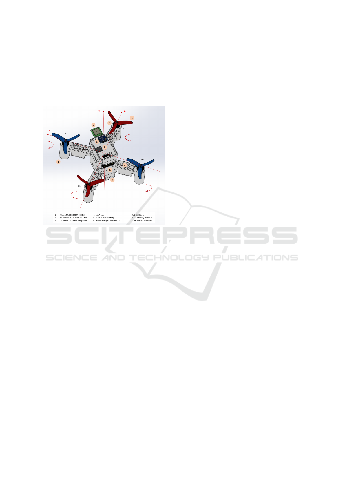
Figure 1: RISC Frame With Actual Hardware Mass, Mate-
rial and Representation Properties.
2.1 CAD based Model Identification
Quadrotors mainly consist of several parts beside the
main frame, more discussion of the main hardware
subsystems are presented in the next section. Each
part is made of certain material and we assume ho-
mogeneity in densities except for parts that are made
of multiple components and each has a considerable
mass relative to the part and the full assembly.
2.1.1 Mass and Inertia Matrix
Mass is calculated for each part in Kilograms and the
full weight of the assembly is computed using the vol-
ume and density of every part utilizing Solidworks
mass calculation and library of materials. The mass
of any part can be overridden if custom designed or
non-standard material is used to build the part. Cen-
ter of Gravity can be estimated numerically which
can be a challenging task. Some experimental ap-
proximation techniques are available. CAD engineer-
ing tools offers accurate calculation of the center of
gravity (COG). Good approximation of COG is in-
deed important as the equation of motions forces and
torques caused by the off center actuators acts on that
point. The non homogeneity of quadcopter different
parts and the way they are assembled affects the loca-
tion of the COG and therefore affect the dynamics of
the vehicle Some heuristics are also employed here by
considering centering the parts with the considerable
relative mass, e.g. batteries. The inertia matrix of a
3D object in free motion is given by:
J =
J
xx
J
xy
J
xz
J
yx
J
yy
J
yz
J
zx
J
zy
J
zz
(7)
Under the assumption of rigid body fixed mass vehi-
cle and alignment of quadcopter axis with the princi-
ple axis of inertia. One can neglect the off-diagonal
inertial components and consider only the principle
moments of inertia J
xx
, J
yy
& J
zz
. Here we take the
vehicle as is and we do not assume symmetrical mass
distribution. The full inertia matrix is computed using
Solidworks Mass Properties utility.
2.1.2 Thrust and Torque Model
The aim of this analysis is to illustrate the use of
CAD simulation to generate the model of the force
and torque effect on the frame exerted by each rotor.
The model of this effect can be complicated which is
in general a nonlinear function of the rotational speed
of the rotor, further detailed discussion are present in
(Mahony, 2012). A quadratic model similar to equa-
tion (4) or a higher polynomial model can be consid-
ered. The goal is to find the rotor parameters p
T
& p
Q
using physics engine of the CAD software. A sub-
assembly that consists of the engine, the propeller and
their mount on the frame is considered for the rota-
tional speed effect of the rotor on the frame as shown
in figure (2). Motion Analysis and Simualtion toolbox
is used to solve for the forces and torques acting the
motor frame interface for a series of rotational speed
s
0
i
, s
1
i
, s
2
i
, ..., s
n
i
where s
0
i
> 0 , s
n
i
< s
max
. s
max
is
the maximum motor rpm which can be found as part
of the engine specifications. One can easily change
the motor/propeller configuration and recompute the
force and torque. An example of force and moment
quadratic fit is shown in figure (2).
Further analysis is carried out to understand the
force and torque models affecting the full frame. Flow
Simulation Toolbox in Solidworks with its embed-
ded computational fluid dynamics (CFD) solver is
used to compute the overall thrust and torque effect
by the four rotors on the frame with all components
mounted. In addition to modeling purpose, this anal-
ysis is useful for design and performance optimiza-
tion. It allows the user to examine different hardware
selections and configurations for better stability and
controllability. Examples of these analyses are:
ICINCO 2017 - 14th International Conference on Informatics in Control, Automation and Robotics
124
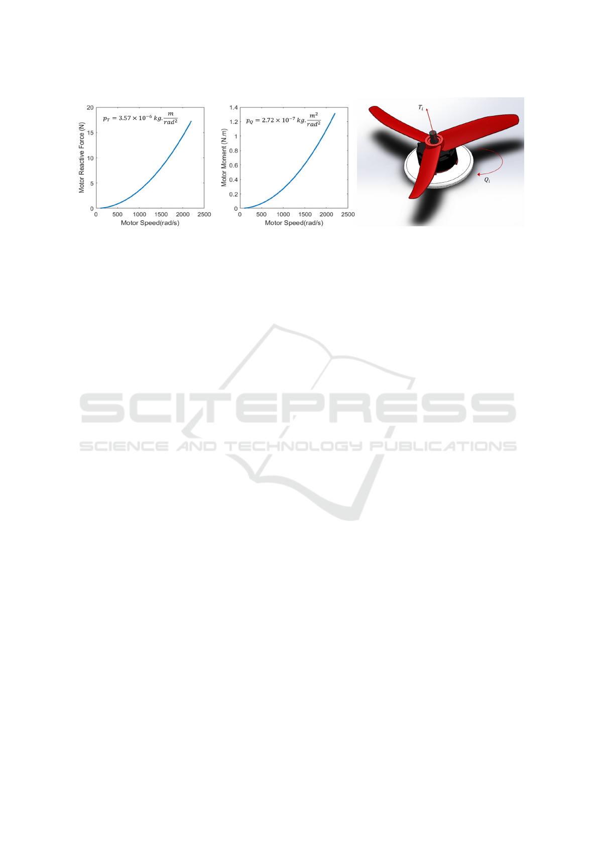
Figure 2: Left: Force and Moment of Brushless Motor and Propeller. Right: Motor/Propeller Model ID Setup In SolidWorks
Motion Analysis Toolbox. Material and Physical Specs Match The Actual Hardware.
• Lift Force Analysis: by rotating the four engines at
variable speeds and recording the generated force
in the body frame z direction. It is important to
make sure the actuators are capable of generating
thrust force that is sufficient to lift the weight of
full frame. Higher maximum thrust is preferable
but it is limited by the motor/propeller selection
which is restricted by the size of the frame and
other power components. See figure (3).
• Vorticity and Turbulence: this analysis can help in
frame sizing. In general, the larger the distance
from center of the quad to center of the rotor (L),
the lower the vorticity and the overall thrust gen-
erated. High value of vorticity affects stability of
the vehicle and make the control more challenging
and less robust(4).
• Frame Optimization: in case of customized de-
sign frame. Vibration analysis of the frame due to
material selection or design geometry to minimize
vibration is desired. High values affects stability
and create large amount of noise in the inertial and
visual sensing components.
• Power Requirements: after the selection of desired
performance and operating time, one need to ex-
amine the system with the extra load of electrical
speed controllers (ESC) and batteries. This pro-
cess can be iterative until a trade-off of total mass,
generated thrust and operating time is found.
• Motor/Propeller Sizing: different combinations of
motor/propellers can be examined to maximize
thrust output and avoid incompatibilities
• Components Reconfiguration: optimizing parts
attachment to the main frame by examining dif-
ferent configurations that led to different mass dis-
tribution and determining maximum and optimal
loading.
• Heat and Structural Stress: this is an advanced
analysis that requires through understanding of
hardware specifications to simulate heat generated
from each component and stress on the frame and
attachment interfaces. This analysis requires ad-
vance simulation tools and considerable computa-
tional resources.
2.1.3 Aerodynamical Effect
The aerodynamical drag can be neglected when op-
erating in near-hover state where φ, θ, ω
x
, ω
y
& ω
z
are zero or close to zero. This effects increases during
rotational and translational motion resulting in deflec-
tion from its desired state or trajectory tracking errors.
Often, this effect is neglected when modeling multi-
rotors unlike the case of fixed wing UAVs and con-
sidered as noise in the model that is compensated for
in the estimation and control level. As the vehicles
becomes larger and more agile, the higher the impor-
tance of modeling or estimating these forces.
A common aerodynamical effect is Blade Flap-
ping that occur mostly when the quadcopter flies in
horizontal translational motion. The advancing blade
of the rotor generates more lift compared to the re-
treating blade which causes inconsistency in the gen-
erated lift and therefore creating oscillation in the ro-
tor blade. This results in shift of the effective thrust
vector. Mathematical modeling of blade flapping
and other aerodynamical effects depends on generated
thrust, rotor size and shape and material properties.
Flow Simulation Toolbox in SolidWorks is used to
generated a table of forces and moments with differ-
ent initial conditions of quadcopter attitudes and ro-
tational speed. The solvers computes the forces and
torques in the three direction F
x
, F
y
, F
z
, τ
x
, τ
y
, τ
z
.
The aerodynamical effect is calculated by subtracting
the rotor thrust and toques from the total values.
An Automated Quadcopter CAD based Design and Modeling Platform using Solidworks API and Smart Dynamic Assembly
125
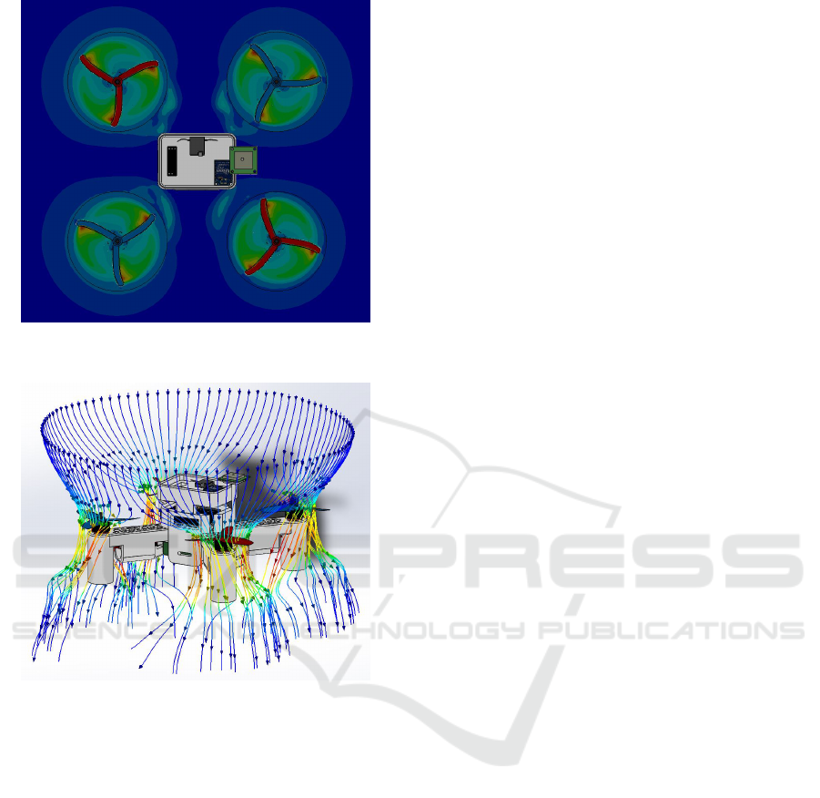
Figure 3: Airspeed Cut Plot Around Propellers (Red: Max-
imum Speed, Blue: Minimum Speed).
Figure 4: Air Profile Around Quadcopter (Red: Maximum
Speed, Blue: Minimum Speed).
3 DYNAMICAL QUADCOPTOR
ASSEMBLY AND SMART
MATING
In this section, the main idea behind automating the
process of CAD design and quadcopter modeling is
presented. The objective is to generate the 3D draw-
ing of each part and this involves geometrical data,
material specifications and visual appearance. Once
the model of every part is generated, the parts are au-
tomatically assembled introducing what we call smart
mating where each generated part is coupled with de-
fault or customized geometrical mating file. This al-
lows parts being connected properly to form the as-
sembly. Some less common parts may have multiple
mating configurations or no default configuration.
3.1 Component Representation
A Quadcopter system consists of several components
attached mainly to the frame. In order to make rep-
resentation easier, different classes of components is
introduced where each class has its special descriptive
parameters that are entered by the user or automati-
cally generated if a hardware part is selected from the
available library. We classify the components as fol-
lows:
• Frame: its parameters includes size, hub length,
hub width, arm width, rotor mount diameter, legs
length, thickness, material, color.
• Engine: main parameters are mass, maximum di-
ameter, minimum diameter, hub size, color, wire
length, wire type, hole spacing, shaft, hight, KV,
input voltage.
• Propeller: parameters are material, hub size,
length, width, pitch.
• Power: this class involves power components like
batteries, ESCs and electronic controller power
module.
• Hardware A: this class contains other additional
components that is commonly present in every ve-
hicle such as flight controller, telemetry module
and RC receiver.
• Hardware B: other additional sensors are present
in this class such as GPS, range finders and cam-
eras.
The components in the last three classes share some
similar parameter descriptions with some few differ-
ences. It is important to note that not all parame-
ters need to be entered by the user and those missing
values are determined from some ratios of the other
parameters. Certain design rules are predefined for
each class and every component in the class to closely
match reality in terms of geometry and visual proper-
ties. Parameters related to material specifications or
hardware interface are essential for some classes like
materials of Frame and Propellers that are important
for the mass and inertial properties as well as motion
analysis and flow simulation. Length of the propeller,
diameter of frame, propeller shaft are examples of pa-
rameters that are important for hardware comparabil-
ity to prevent sizing or overloading issues. A template
of the design and the model parameters are the two
main components, the desired part can be generated
using one of the following approaches:
1. Full model drawing: it requires considerable
amount of time and engineering design experi-
ence. The model can be made with realistic ge-
ometrical and appearance details.
ICINCO 2017 - 14th International Conference on Informatics in Control, Automation and Robotics
126

2. Template manual modification: as part of this
work, a CAD drawing and properties file is cre-
ated. One can update this template file with di-
mensions, mass and material properties of the de-
sired part design.
3. Macro file modification: if a Macro file exists for
the part template, the user can modify the param-
eters in the Macro code to match desired model.
It requires familiarity with Macro file format and
the 3D design software currently in use.
4. Solidworks API: the application programming in-
terface offers interacting with the engineering de-
sign software through another compatible appli-
cation or standalone applications. API is utilized
in this work to automate the process of generating
the model of each part and many other tasks.
The process of automated part generation start by get-
ting the part specifications/parameters from its techni-
cal description, e.g. webstore, datasheet, ...etc. This
data is entered by the user in an application with
Graphical User Interface (GUI) prompting the user
to enter the proper data. The software uses this en-
tered data and the selected hardware class to gener-
ate the parameter description file. Once generated,
these parameters are used to generate a custom call
to the design software (Solidworks is used in this
work) through its API to generate the model from
scratch to satisfy the entered parameters or modify
one of default templates if they exist within the hard-
ware database. This process is illustrated in the chart
shown in (5).
3.2 Smart Mating
Assemblies and parts are the building blocks for cre-
ating the final model of the vehicle. Assemblies are
created by mating parts; introducing geometrical re-
lations between different entities of the parts such as
surfaces, faces, edges and vertices. This is usually
done using assembly mating utility within the design
software. To automate this mating process, one can
introduce rigid geometrical relations between parts
where a specific face/edge from one part is mated with
another compatible entity in the other part. Although
this approach is doable through the software API au-
tomatically, it poses multiple challenges.
The number of possible sub-assemblies grows
with the number of components option which loads
the database further and slow down the process. Ad-
ditionally, it limits modularity of the design which
would make creating a custom model or a sub-
assembly that does not exist in the library more time
consuming and less immune to mating or rendering
errors due to irregularities in some parts’ geometry.
Smart mating is a virtual massless properties that
can be for instance surfaces and edges introduced for
every part. The purpose of these virtual entities is in-
troducing one of multiple mating configurations. Mo-
tors are mounted to the frame using their own mount-
ing bases while propellers are mounted to propeller
through circular alignment of their hubs and the mo-
tors’ hubs.
This configuration of parts can be seen as a pre-
conditioning step to allow smoother automated gen-
eration of the quadcopter assembly. It allows proper
universal way to integrate parts in different vehicles
and early detect incompatibility of parts and sub-
assemblies and therefore prevent possible rendering
errors in the design or degraded performance. Modu-
larity is another strength of this approach where parts
can be exchanged within the software and multiple
combinations can be tried.
Each part to be generated requires two descriptor
files: the first includes the parameters of the compo-
nent that are related to physical and appearance prop-
erties as illustrated in (3.1). The second descriptor
includes information regarding the virtual mating en-
tities and specifies default and alternative configura-
tions. It is essential for the mate descriptor to include
the class of the component and part type.
The process starts with having at least two compo-
nents with their parameters files created as mentioned
previously. The software will start searching for the
mating data of each component. If these files does not
exist, then it is created with the assumption that part
is in the default orientation. If the files exist, then the
software will examine the type of available mates and
its compatibility with the other mates. This insures
the proper parts are being mated. Figure (6) shows an
example of mating surfaces in an airframe.
Each virtual entity in the smart mate file is as-
signed a class and type of hardware. For instance,
a quadcopter frame mating configuration file would
have several virtual surfaces to mount other different
types of hardware. None of these surfaces correspond
to propellers as they are not in physical contact with
the frame. When mating multiple components to the
frame, the software searches for the mate identity in
the frame and match it with its corresponding peer in
the other parts.
4 AUTOMATED QUADCOPTER
MODEL GENERATION
The developed software tool that automate the full
design and modeling process described in the previ-
ous two sections. The system structure is first dis-
An Automated Quadcopter CAD based Design and Modeling Platform using Solidworks API and Smart Dynamic Assembly
127
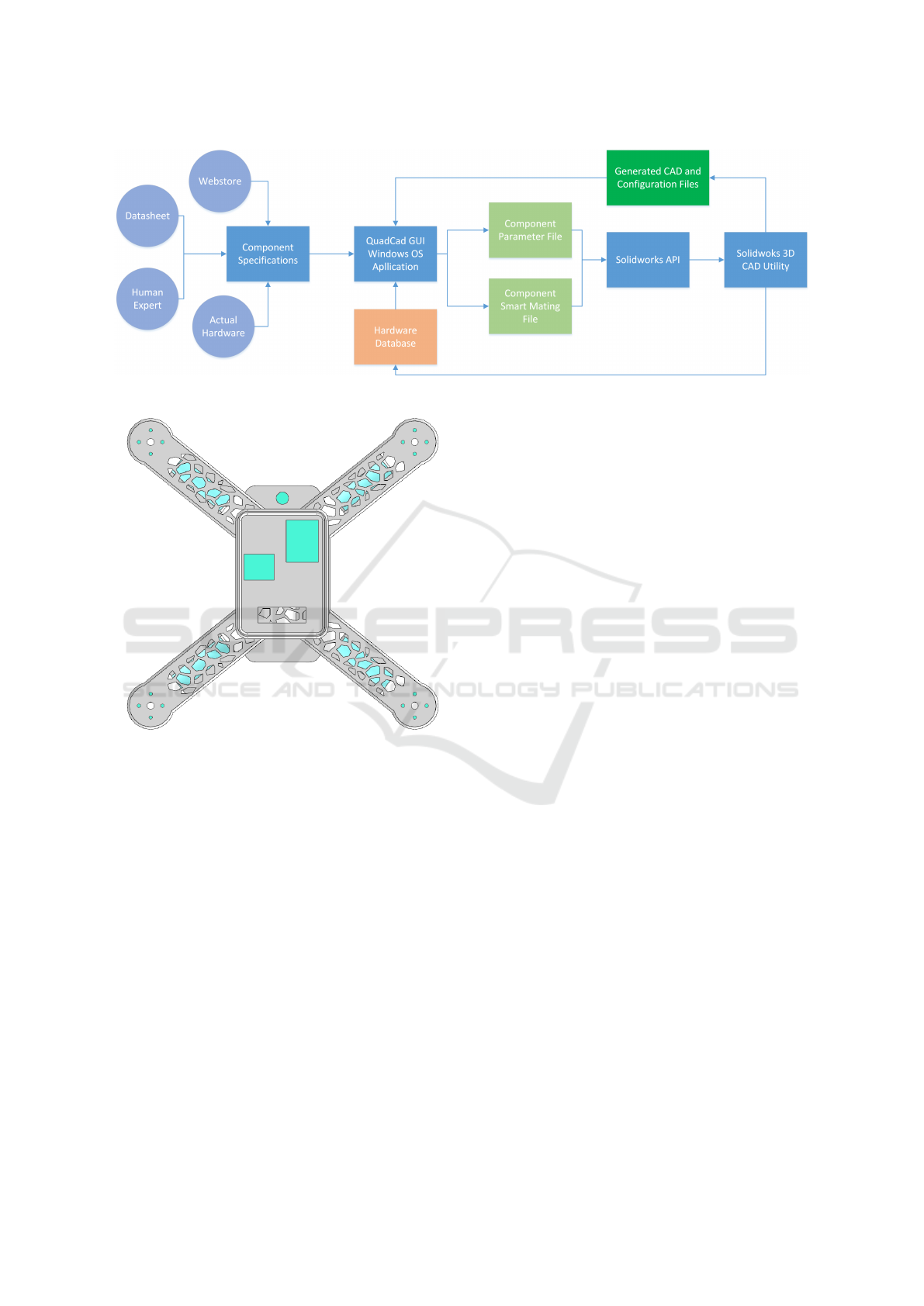
Figure 5: Automated Component Generation Process.
Figure 6: RISC Pixhawk Frame (Top View) With High-
lighted Smart Mating Surfaces.
cussed then the friendly user interface application
is illustrated. Some details of how the Solidworks
API works and the analysis toolboxes are deliberately
omitted here for the sake of focusing the discussion
on the proposed system and developed software, more
details on explaining the functionality of these can be
found in (Kurowski, 2013), (Matsso, 2013).
4.1 System Structure
The system aims to simplify the process of acquir-
ing detailed models that improve the mathematical
and visual description of a model under control study.
It relieves the need for design experience and system
identification using the an automated CAD based 3D
design and modeling. The overall system structure
is shown in figure (7). The system consists of three
main components, User interface, Software layer that
is the main novelty of this work and the CAD based
design and modeling which is handled by Solidworks
3D design utility, solvers and simulation tools. The
first component is presented in (4.2). The third com-
ponent is discussed in the first 2 sections. In this sec-
tion, the software layer is discussed. Four main func-
tions are performed within this layer.
• Hardware Configuration Files: these are the de-
scriptive .XML files of every part in the assembly.
The content of each file may differ depend on the
class and type of hardware as described earlier.
The file contains physical and geometrical param-
eters of the hardware it is describing. It worths
noting that this file can be generated by typically
reading input data from the user but it can also
be constructed from the CAD models if they ex-
ist. The smart mating configuration files are also
generated for every components to include the de-
scription of the correct orientation and attachment
interface for each part in the assembly.
• Hardware Database: it includes generic compo-
nents and off-the-shelf components 3D designs,
parameters and mating descriptors. This allows
the user to rapidly prototype or customize par-
tially or fully the desired design. The CAD de-
signs are saved as model files to allow quick re-
trieval for components in a different assembly and
dynamic Macros to allow easy modifications of
the components for utilization in updated models.
This database save tremendous amount of time
and computational cost by avoiding performing
the designs from scratch every time the user run
the application.
• Solidworks API Interface: this is the core bridg-
ing function between QuadCAD application and
Solidworks engineering tools (Shen, 2014). The
first basic functionality is 3D modeling of parts
by reading the hardware parameters files and con-
verting them to geometrical programming com-
ICINCO 2017 - 14th International Conference on Informatics in Control, Automation and Robotics
128

mand. Then the mating data is be integrated
through introducing virtual geometrical features
to the designed parts. After that, the assem-
bly function scans the parts configuration files
and mating properties and try to fix any simple
incompatibility by introducing dynamic adapters
between parts and generate warning or errors if
serious hardware conflicts occur between the se-
lected components. The parts are mated using
the smart mate interface in every part to create
sub-assemblies and the main assembly. The mass
properties are then calculated before starting the
motion analysis and flow simulations. The user
choose to perform the CAD based modeling and
select operating conditions and accuracy of anal-
ysis.
• Simulation File Generation for Matlab Simscape:
the application received the simulation results
for the CAD utility and generate model parame-
ters m-file and nonlinear dynamical model of the
quadcoptor utilizing the vehicle equations of mo-
tion. In addition, the CAD models and Simscape
simulation files are generated using a modified
version of the files produces by the Solidworks-
Matlab add-on.
Additional functions related to operating system and
computation and memory resources handling in ad-
dition to interfacing and file processing functions are
not discussed in this context.
4.2 User Interface
The application is developed using Microsoft Visual
Studio Visual Basic and the graphical user interface is
developed using VS WPF (Schneider, 2013). The cur-
rent version run on Windows 7 OS and later. The inter-
face shown in figure (8) is simple self descriptive that
consists of multiple tabs. The first three tabs where
the user inputs hardware specifications for parts or
choose off-the-shelf or previously saved components
instead. If the user skipped one of parts, then the soft-
ware add this part to the assembly if it essential and
neglect it if it is optional. In either case the user is
given a warning for the missing or mismatched com-
ponents. In the Assembly Setting tab, the options to
select default smart mating or custom mating can be
found with other special options to choose one config-
uration in case the component has multiple mounting
possibilities.
Modeling Setting tab contains the analysis and
CAD simulations parameter. The user can here select
the option to apply all system identification related
simulations or select some of them. This part is the
most consuming for computer resources and gener-
ation time especially if high accuracy high resolution
design simulation is required. The process of generat-
ing the CAD model of a quadcopter with good model
identification last for 13-16 hours on an i7 processor
and 8GB RAM laptop machine. This time exponen-
tially increases with the increase in mesh resolution
or solvers constrains.
The Simulation Setting Tab lists the options that
are related to generating the Matlab/Simulink files
with 3D Simscape model with the available simula-
tion setup and assumption. The quadcopter model
assumptions are chosen in this part. The user can
choose to generate the 3D model with its parameters,
the mathematical model or both.
4.3 Simulation Files Generation for
Matlab Simscape
The generated matlab simulation files are combina-
tion of CAD models converted to a format compatible
with Simscape simulation utility. Simulink models
are generated for the control purpose. These are either
models describing the physical system components
for Simscape simulations or mathematical models of
quadcopters for model validation or model based con-
trol design purposes. Other files involve environmen-
tal and gravitational effects in the simulation environ-
ment, system parameters and plotting functions.
The generated simulation setup allows the user
to focus on the design and assessment of controllers
for multirotors vehicles. The inputs to the simulation
model are the rotational speed of the rotors s
1
, s
2
, s
3
,
and s
4
and the outputs are 12 states, 6 translation mo-
tion positions and velocities and 6 rotational motion
attitude and rotational speeds. In addition to stability
and tracking controllers, one can consider advanced
robustness analysis against external disturbances or
operating under partial or full hardware failure. This
can be done through examining different configura-
tions of the Simscape simulation.
5 CONCLUSION AND FUTURE
WORK
An automated software system for the design and
modeling of quadcopter UAV is presented. The appli-
cation is build with a user friendly interface to atten-
uate the difference between quadcopter simulations
and actual experimentation. The system with its hard-
ware library allows the user to rapidly build custom
models with realistic components specifications and
visual representation. Benefiting from the state of the
An Automated Quadcopter CAD based Design and Modeling Platform using Solidworks API and Smart Dynamic Assembly
129
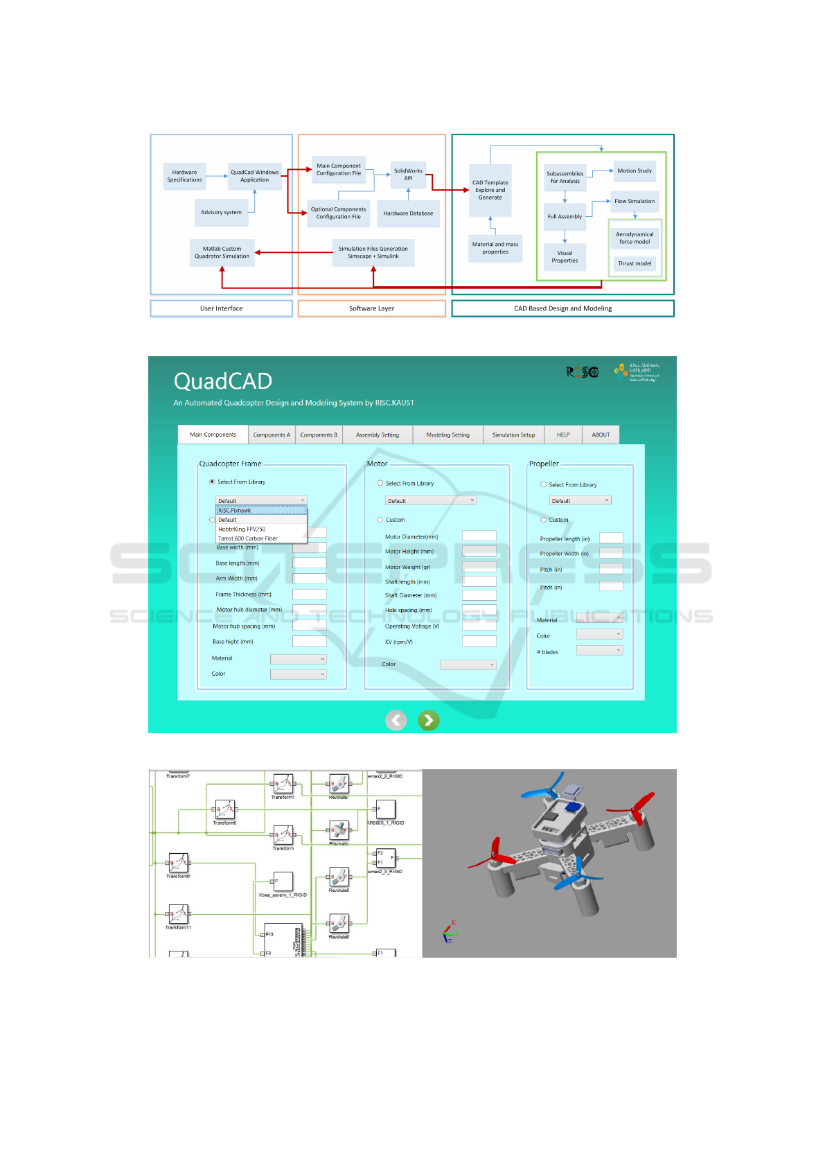
Figure 7: Automated Quadcopter Design and Modeling System Overview.
Figure 8: QuadCAD Design and Modeling Software Interface.
Figure 9: Simscape/Simulink Quadcopter Simulation.
ICINCO 2017 - 14th International Conference on Informatics in Control, Automation and Robotics
130

art CAD based design and analysis tools, we build
and easy to use method to generate high quality mod-
els with that do not require prior expertise with this
class of engineering tools. User can iterate between
control design and hardware system examining.
This software is being developed and maintained
by the Robotics, Intelligent Systems and Control Lab
(RISC) at KAUST. We intend to make this project
available for community through an online database
for designers and researchers collaboration. Although
this system is built based on Solidworks API and the
its tools, the concept can be generalized to other CAD
software or standalone system if the appropriate utili-
ties and solvers are available.
Further improvements can be done on the opti-
mization of the application performance and cross
platform availability. Additional more detailed mod-
eling of quadcopter can be considered or simpler
models can be investigated for control development
purposes. Beside the main objective of the system
which is simplifying design and modeling for control
development, it can be used as a hardware advisory
system where users examine different combination of
components and the effect on performance. Further
functionality can be added to the Matlab simulation
environment and other simulation platforms can be
supported.
REFERENCES
Mahony, R., Kumar, V., & Corke, P. (2012). Multirotor
aerial vehicles. IEEE Robotics and Automation mag-
azine, 20(32).
Domingues, J. M. B. (2009). Quadrotor prototype. Unev-
ersidade Tecnica deLisboa. Dissertacio.
Corke, P. I. (1996). A robotics toolbox for MATLAB. IEEE
Robotics & Automation Magazine, 3(1), 24-32.
Rohmer, E., Singh, S. P., & Freese, M. (2013). V-
REP: A versatile and scalable robot simulation frame-
work. In Intelligent Robots and Systems (IROS), 2013
IEEE/RSJ International Conference on (pp. 1321-
1326).
Simscape, Matlab Toolbox (2016). Natick, Massachusetts:
The MathWorks Inc..
Zhang, X., Li, X., Wang, K., & Lu, Y. (2014). A survey
of modelling and identification of quadrotor robot. In
Abstract and Applied Analysis (Vol. 2014). Hindawi
Publishing Corporation.
Kuantama, E., Craciun, D., Tarca, I., & Tarca, R. (2017).
Quadcopter Propeller Design and Performance Anal-
ysis. In New Advances in Mechanisms, Mechanical
Transmissions and Robotics (pp. 269-277). Springer
International Publishing.
Kurowski, P. (2013). Engineering Analysis with SolidWorks
Simulation 2013. SDC publications.
Matsson, J. E. (2013). An Introduction to SolidWorks Flow
Simulation 2013. SDC publications.
Sa, I., & Corke, P. (2012). System identification, estima-
tion and control for a cost effective open-source quad-
copter. In Robotics and automation (icra), 2012 ieee
international conference on (pp. 2202-2209). IEEE.
Shen, H., Yang, Y., & Zhang, J. (2004). SolidWorks API
methods based on VB technology [J]. Computer
Aided Engineering, 4, 014.
Schneider, D. I. (2013). An Introduction to Programming
Using Visual Basic 2012. Prentice Hall Press.
Koenig, N., & Howard, A. (2004). Design and use
paradigms for gazebo, an open-source multi-robot
simulator. In Intelligent Robots and Systems,
2004.(IROS 2004). Proceedings. 2004 IEEE/RSJ In-
ternational Conference on (Vol. 3, pp. 2149-2154).
IEEE.
Meyer, J., Sendobry, A., Kohlbrecher, S., Klingauf, U., &
Von Stryk, O. (2012) Comprehensive simulation of
quadrotor uavs using ros and gazebo. In International
Conference on Simulation, Modeling, and Program-
ming for Autonomous Robots (pp. 400-411). Springer
Berlin Heidelberg.
An Automated Quadcopter CAD based Design and Modeling Platform using Solidworks API and Smart Dynamic Assembly
131
