
Refactoring Object-Oriented Applications for a Deployment in the Cloud
Workflow Generation based on Static Analysis of Source Code
Anfel Selmadji, Abdelhak-Djamel Seriai, Hinde Lilia Bouziane, Christophe Dony
and Chouki Tibermacine
LIRMM, CNRS and University of Montpellier, Montpellier, France
Keywords:
Object-Oriented, Refactoring, Workflow, Data Flow, Control Flow, Cloud.
Abstract:
Cloud Computing delivers to customers computing/storage resources as services via the internet. It is charac-
terized by its elastic nature and its payment model (pay-as-you-go). To optimize the use of these resources, one
of the requirements related to this type of environment is to dynamically configure the applications to reduce
the costs of their deployment.The dynamic configuration requires the ability to determine which resources
are used, as well as when and where they are utilized. This can be done using workflows. In fact, several
works rely on workflows to reduce execution costs in the cloud. Unlike workflows, OO applications have an
architecture which exposes little or no behavioral (temporal) aspect. Hence, to execute an OO application in
the cloud, the entire application needs to be deployed and all its used resources need to be allocated during its
entire execution time. To reduce execution costs, we propose a re-engineering process aiming to restructure
these applications from OO architectural style to workflow style. In this paper, we focus on the first step of
the process which has as a goal generating a workflow from OO source code.
1 INTRODUCTION
Cloud computing is a technology that uses the internet
and central remote servers to provide services for its
customers on demand (Kaur et al., 2011; Mell et al.,
2011). Google App Engine, Amazon EC2, Aneka
and Microsoft Azure are some of the prominent cloud
computing platforms (Masdari et al., 2016).
Generally, the services provided by the cloud can
be classified as SaaS (Software as a Service), PaaS
(Platform as a Service) and IaaS (Infrastructure as a
Service) (Wu et al., 2013). SaaS is a software deli-
very paradigm, where the software is developed by
service providers and delivered via internet (Espadas
et al., 2013). PaaS provides platforms to develop
and deploy applications in cloud infrastructure using
programming languages, libraries and so on (Fak-
hfakh et al., 2014). IaaS providers deliver proces-
sing, storage, network and other fundamental com-
puting resources to deploy and run customers’ soft-
ware (Dillon et al., 2010; Mell et al., 2011). In fact,
customers can provision resources (e.g. processors,
storage space, network, etc.) whenever they want and
release them when they are no longer needed (Dillon
et al., 2010). However, based on the ”pay-as-you-go”
model, customers are usually charged following the
resource usage. Consequently, it is important to have
the ability to adjust this usage, i.e., allocate resources
only when needed and release them when they are no
longer used, in order to reduce costs. This can be done
by dynamically allocating and releasing resources ba-
sed on their usage (Fakhfakh et al., 2014; Xu et al.,
2009). Nevertheless, the dynamic allocation and rele-
ase requires determining, for each application, which
resources are used, as well as when and where they
are utilized.
Object-Oriented (OO) style is one of the most
used architectural styles to develop software applica-
tions (Taylor et al., 2009; Garlan and Shaw, 1993).
However, without any prior restructuring, to execute
an OO application in the cloud, the entire application
needs to be deployed and all its used resources need
to be allocated during its entire execution time. Con-
sequently, a customer will be billed based on the used
resources even if some of them were unnecessarily
occupied for certain periods (Fakhfakh et al., 2014).
For the data used by certain types of applications
such as scientific ones, it is possible to determine the
required resources to execute them: storage space,
network, processor, etc. These resources are neces-
sary for the storage, acquisition/transmission and pro-
cessing of data.
Selmadji, A., Seriai, A., Bouziane, H., Dony, C. and Tibermacine, C.
Refactoring Object-Oriented Applications for a Deployment in the Cloud.
DOI: 10.5220/0006699101110123
In Proceedings of the 13th International Conference on Evaluation of Novel Approaches to Software Engineering (ENASE 2018), pages 111-123
ISBN: 978-989-758-300-1
Copyright
c
2019 by SCITEPRESS – Science and Technology Publications, Lda. All rights reserved
111

The data flow architectural style is adapted to de-
ploy this kind of applications in the cloud. In fact, this
style focuses on how data moves between processing
elements of an application (Taylor et al., 2009; Bass,
2007). Hence, these elements and their consumed/-
produced data are explicitly identified allowing to de-
termine resources needed by each one of them. In ad-
dition, it allows to determine when each element can
be executed, and therefore when its needed resour-
ces are used. Note that, by extending the data flow
style with a richer control flow, i.e. a control flow that
expresses sequences, conditional branches and loops,
an architectural style that represents a workflow (Hol-
lingsworth, 1995), in which each architectural com-
ponent is a task, can be obtained. Several works
rely on the data flow style in order to perform dyn-
amic configuration to optimize resources usage in the
cloud, and thus to reduce execution costs (Zhu et al.,
2016; Masdari et al., 2016; Fakhfakh et al., 2014; Xu
et al., 2009; Lin and Lu, 2011).
In order to deploy OO applications in the cloud
while reducing costs, we propose a re-engineering
process aiming to restructure these application from
OO architectural style to data flow style. In this paper,
we focus on the first step of the process which has as a
goal generating a workflow description from existing
OO application. This generation requires the ability
to map OO concepts into the worklow ones. For ex-
ample, we need to determine what is the mapping of
the concept task compared to the OO concepts. Once
such a mapping is defined, the refactoring consists,
in recovering the constituents of a worklow from a
source code, i.e. a set of tasks, a control flow and a
data flow.
The originality of our approach can be viewed
from two aspects. On the one hand, we use source
code refactoring in order to adopt OO application to
a deployment in the cloud instead of either executing
them with high costs or redeveloping them from scra-
tch. On the other hand, techniques used in our ap-
proach allow us to recover the entire workflow while
a majority of the existing works (e.g. (Kosower and
Lopez-Villarejo, 2015), (Korshunova et al., 2006),
(Zou et al., 2004) ) propose to extract only a part of a
workflow (i.e. either control flow or data flow). More-
over, although some approaches propose to extract a
description of the workflow by analyzing source code,
they do not propose to generate the code of this work-
flow (see section 7).
The remainder of this paper is organized as fol-
lows. Section 2 presents a possible mapping from OO
concepts to workflow ones and announces addressed
refactoring issues. Section 3 presents a solution for
task identification, while section 4 presents control
and data flow recovery solutions. Section 5 discusses
a workflow implementation. Section 6 evaluates our
proposal. Section 7 outlines related works. Finally,
section 8 concludes the paper.
2 OBJECT-ORIENTED VERSUS
WORKFLOW-BASED
ARCHITECTURAL STYLES
2.1 Background : Workflow-Based
Style
The term workflow has been initially defined by the
WorkFlow Management Coalition (WFMC) in 1995
(Hollingsworth, 1995) as:
”The computerized facilitation or automation of a
business process, in whole or part.”
This standard definition proposes a reference mo-
del for the creation, deployment and control of work-
flow applications. It refers to a workflow as a solu-
tion for business processes automation. A process is
defined as a coordinated sequence of a set of tasks le-
ading to a determined result. Coordination specifies
the sequencing mode of tasks, as well as the data ex-
changed between them. In other words, a workflow
can be seen as an application constructed by a set of
tasks, with possibly dependencies specified by follo-
wing two classical formalisms: data flows and control
flows. In this paper, these concepts are defined as fol-
lows:
• Task: a task is the basic unit of composition of
a workfow. It is the smallest execution unit, re-
presenting an execution stage in a whole applica-
tion. Its implementation is independent of other
tasks and can be reused in different contexts. A
task can define input and output data, where input
data represent data required for executing the task
and output data, the produced ones. A task can be
either primitive or composite. A composite one
can be viewed as a sub-workflow enclosing pri-
mitive or composite tasks.
• Control Flow: a control flow describes the exe-
cution order of tasks through different constructs
such as sequences, conditional branches (if and
switch) and loops (for and while).
• Data Flow: a data flow specifies data dependen-
cies between tasks. If the outputs of a task T
i
are
inputs of a task T
j
, then the execution of T
j
de-
pends on that of T
i
.
Figure 1 shows an example of a workflow con-
sisting of three tasks. On the one hand, the control
ENASE 2018 - 13th International Conference on Evaluation of Novel Approaches to Software Engineering
112
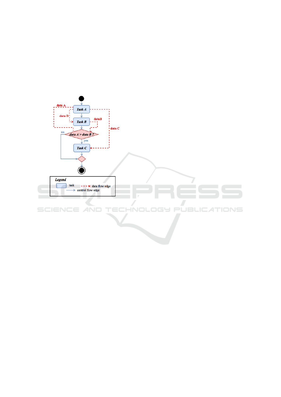
flow specifies that Task A and Task B are executed se-
quentially, whereas Task C can be executed only if
the condition ”data A>data B” is true. On the ot-
her hand, the data flow indicates that Task A produces
three output data data A, data C and data D, while
Task B produces an output data data B. data D and
data C are respectively used by Task B and Task C,
whereas data A and data B are utilized to evaluate the
condition ”data A>data B”.
Figure 1: Example of a workflow.
2.2 A Mapping from Object-Oriented
Code to Workflow
A task is the basic unit of composition of a workfow.
It is the smallest execution unit, representing an exe-
cution stage in a whole application. Based on this de-
finition, we consider that a method can be mapped to a
task in a workflow (see Figure 2). In particular, we as-
sume that a method that contains only assignment sta-
tements or invokes only methods provided by a stan-
dard library is mapped to a primitive task, a method
that includes a sequence of methods invocations and
control statements is mapped to a composite task. For
methods including both methods invocations, control
statements and other statements, the source code has
to be refactored to wrap these later in a method. In
fact, a workflow, as seen in Figure 2, does not include
assignment statements as a unit of composition.
A task can define input and output data, where
input data represent data required for executing the
task and output data, the produced ones. Due to the
fact that a task corresponds to an OO method, task in-
puts represents data needed to execute the correspon-
ding method, while task outputs is the data produced
from this execution. In order to be executed, a met-
hod requires a receiving object and its input parame-
ters. Once executed, the method’s produced data is
its modified inputs (i.e. receiving object and/or input
parameters), and/or its output parameter (i.e. returned
value). Hence, each method’s produced data that re-
presents a modified input corresponds to two data in a
workflow, an input and an output data (see Figure 2).
In a workflow, the execution order of tasks is ex-
pressed using different control constructs such as se-
quence, conditional branches and loops. In OO style,
the execution order of methods invocations, which
corresponds to the execution of tasks, depends on
control statements (e.g. if statement, while statement,
etc.). Hence, we chose to consider that a control state-
ment can be mapped to a control construct. Thus, the
input data of a control construct corresponds to data
manipulated in the corresponding control statement,
i.e. in the condition and the body of the control sta-
tement, while control construct outputs are the data
defined in the control statement and used in the follo-
wing statements.
The explained mapping between OO concepts and
workflow ones is illustrated in Figure 2.
2.3 Refactoring Process and Issues
Our goal is to generate a workflow based on static
analysis of OO source code. In order to achieve this
goal, a refactoring process, that can be seen as a re-
engineering horseshoe model (see Figure 3), was pro-
posed. The existing OO system is represented on the
left side of the figure and the target system on the right
side.
The refactoring process consists of three steps.
These steps are represented in Figure 3. In the first
step, existing source code is analyzed to identify
the application structural elements (classes, methods,
etc.) and their links (method calls, class inheritances,
etc.). The aim of the second step is to map OO con-
cepts to wokflow ones. Starting by, identifying pri-
mitive and composite tasks (see section 3), as well as
their respective input and output data, and then reco-
vering the control flow and the data flow (see section
4) associated to these tasks to preserve the same be-
havior then the OO application. The last step of our
process consists of transforming the OO source code
to conform to this workflow (see section 5).
For this refactoring process, we chose to preserve
the object entities of the original source code to gene-
rate the new structure of the application. This means
that object instances will not be transformed into pri-
mitive elements (i.e. the values of their attributes).
Thus, the result of the refactoring is an implementa-
Refactoring Object-Oriented Applications for a Deployment in the Cloud
113
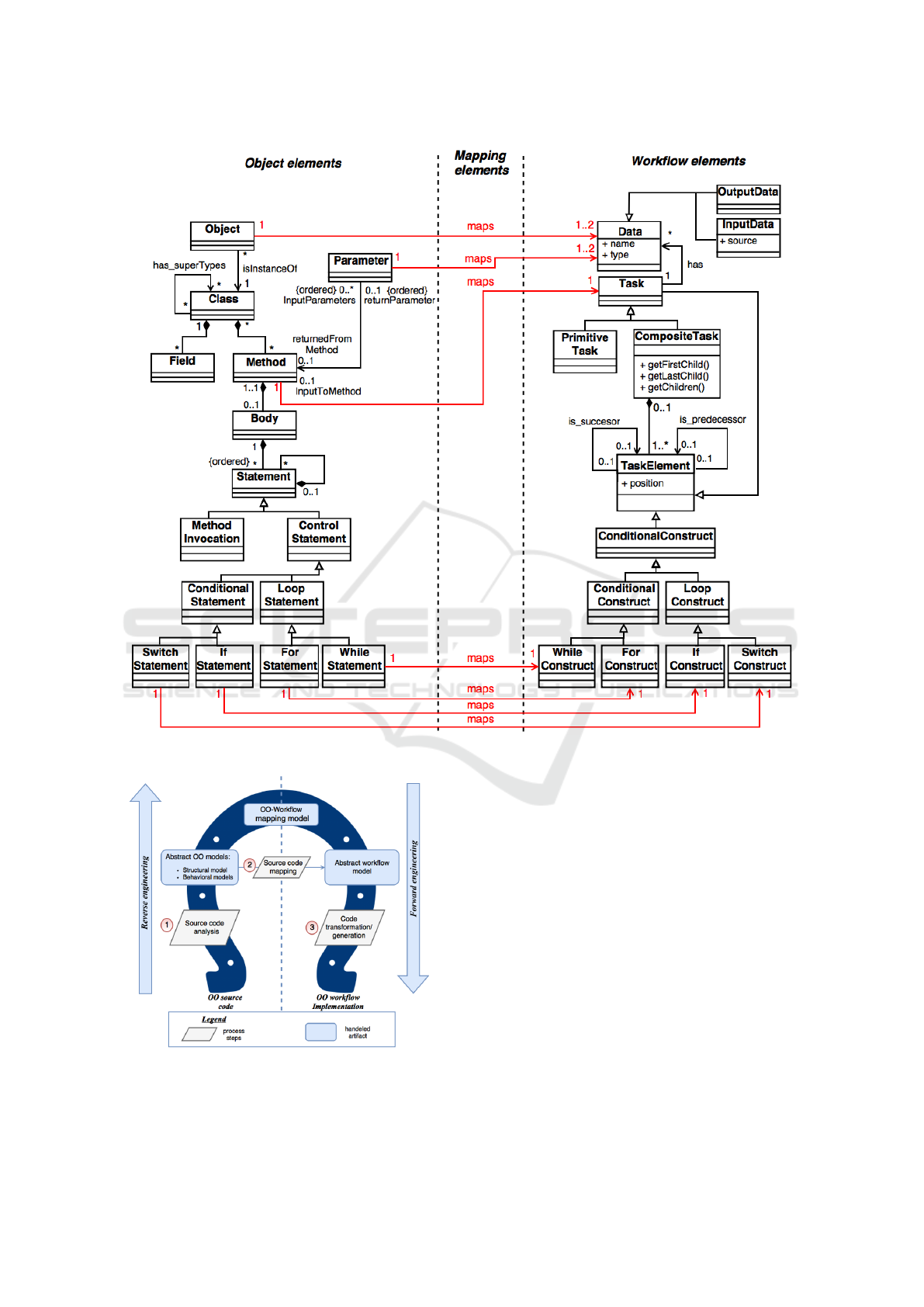
Figure 2: From OO elements to workflow ones: the mapping model.
Figure 3: OO versus workflow: the re-engineering process.
tion based on ”task” entities connected by input and
output data and whose control flow is explicitly repre-
sented at the architectural level. In other words, the
target source code is composed of task entities, im-
plemented based on the object entities of the original
source code.
The realization of this process requires answering
the following questions:
• Q1: what are the tasks that reflect the workflow
corresponding to the analyzed OO application?
The answer to this question requires identifying
a matching at the instance level between task enti-
ties and OO methods invoked on object instances.
• Q2: what is the control flow to be defined bet-
ween the identified tasks with preservation of the
same behavior as the analyzed OO application?
The answer to this question requires, among ot-
hers, to make explicit the implicit control flow due
to OO features, for example, polymorphism and
dynamic binding.
• Q3: what is the data flow to be associated with
ENASE 2018 - 13th International Conference on Evaluation of Novel Approaches to Software Engineering
114

the identified tasks and control flow? The goal is
to define for each task its input and output data
in such a way that the application architectured as
tasks gives the same results as the application ar-
chitectured as objects, i.e. given the same inputs,
the two variants of the application produces the
same outputs. This is mainly to identify the flow
of objects attached to tasks already identified.
• Q4: what model of implementation to structure
the target application into new object entities that
reflect the identified tasks, control flow and data
flow while preserving the object entities of the ori-
ginally crafted application?
3 TASK IDENTIFICATION
Our OO-to-Workflow mapping model establishes a
unique mapping for a workflow tasks, a task corre-
sponds to a method in the OO source code (see Fi-
gure 2). Thus, we transform all statements that do
not represent method invocations in the OO code into
method invocations based on code refactoring. Once
this refactoring is done, we determine among all the
code methods those to transform into primitive tasks
from those to transform into composite ones. Finally,
we determine the input and output data for each task.
3.1 Extract Method Refactoring
The refactoring of OO source code consists to extract
each sequence of statements delimited by user method
invocations as a new method and replace the sequence
by an invocation of this method. Note that, only state-
ments that belong to the same block can be extracted
to ensure that the new method is syntactically correct.
Figure 4 shows an example of extract method re-
factoring. In this example, the statements delimited
by method invocations method1() and method2(a) do
not belong to the same block and thus it is not pos-
sible to extract them as a new method. Nevertheless,
this sequence can be divided into two fragments ba-
sed on whether the statements belong to the same bloc
or not. Each fragment is extracted as a new method
(method m1 and method m2).
Once statements to be extracted are identified, the
extraction begins. Variables acceded (defined or used)
but not declared by these statements (i.e. the variables
declaration statements do not belong to these state-
ments) should be passed in as input parameters of the
new method. Whereas, variables defined by these sta-
tements and acceded by following fragments should
be passed out as its output parameters. Note that, a
variable is considered as defined if its value is modi-
fied (i.e. writing access) and it is considered as used
if its value is read (i.e. reading access).
Figure 4: Example of extract method refactoring.
Some OO languages, such as Java, imposes that a
method can not have more than one output parameter
(i.e. returned value). Thus, if a sequence of state-
ments has multiple output values, this sequence will
be divided into several fragments. Each one of them
is extracted as a new method and return at most one
output parameter. This code fragmentation and met-
hod extraction do not re-order code statements, which
eliminates the possibility of breaking down program
semantics.
3.2 Task Identification based on
Analysis of the OO Application Call
Graph
A workflow consists of two types of tasks: primitive
and composite ones. As a task is mapped to an OO
method, then a method that does not include calls to
other ones is considered as a primitive task, otherwise,
it is a composite one. The identification of primitive
and composite tasks is based on the analysis of the
OO application’s call graph.
In order to build a call graph, the source code is
analyzed to determine for each caller method its cal-
lees. Call graph leafs are mapped to primitive tasks,
whereas the rest of nodes are mapped to composite
ones.
A particular case related to the analysis of the
call graph concerns direct or indirect recursive calls.
Since recursive transitions between tasks (i.e. the abi-
lity of a task to invoke itself directly or indirectly du-
ring its execution) are not always supported by work-
flows (Russell et al., 2006), recursive calls between
methods are transformed as follows: a method M in a
directed cycle is mapped to a primitive task if all the
methods invoked by M belong the this cycle (see met-
hod Foo.incX in Listing 1). Otherwise, this method is
mapped to a composite task (see method Foo.setX in
Listing 1).
Refactoring Object-Oriented Applications for a Deployment in the Cloud
115
Listing 1: Classes Foo, Bar and Main.
1 class F oo {
2 int x ;
3 void s et X (int y , boolean i s Di f f er e n t ){
4 if ( is D i ff e r en t )
5 in i t ia l i ze X ( y ) ; i ni t i al i ze
6 else
7 inc X ( 2* y ); }
8 int i nc X (int y ){
9 if ( x != y )
10 set X ( y , true);
11 else
12 set X ( y , false);
13 return x ;}
14 int g et X ( ){
15 return x ;}
16 void in i ti a l iz e X (int y ) {
17 x = y ;} }
18 class B ar {
19 Foo f oo = new Foo ( );
20 void m ( ){
21 foo . i ni t i ali z e X ( 1) ;
22 int x = fo o . g et X () ;
23 while (x < 2 0) {
24 x = fo o . in c X ( x ); }} }
25 class M ai n {
26 static B ar b ar = new Ba r () ;
27 public static void m ai n ( S tr i ng [ ] a r gs ){
28 bar . m () ;} }
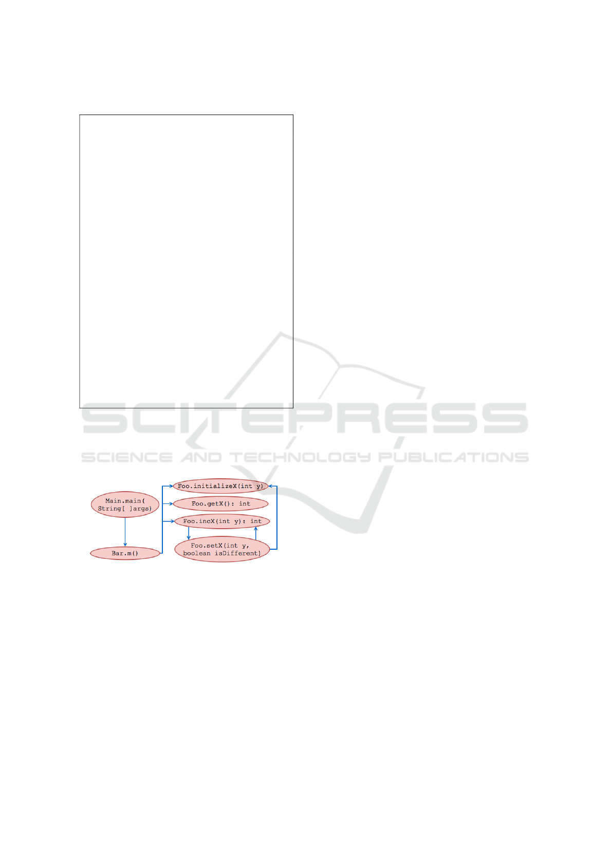
Figure 5 represents the call graph built from
the source code shown in Listing 1. The met-
hods Main.main, Bar.m and Foo.setX map compo-
site tasks, while the methods Foo.initializeX, Foo.getX
and Foo.incX correspond to primitive tasks.
Figure 5: Call graph built from the source code shown in
Listing 1.
3.3 Identifying Tasks Inputs and
Outputs
Each of the identified tasks, primitive or composite,
have input and output data. As explained in section
2.2, the inputs correspond to the parameters and the
receiving object of the corresponding method, whe-
reas the outputs are the inputs that have been modified
and the returned value by the corresponding method.
Note that the modified inputs of a task are considered
as its outputs because their new values are produced
by this task.
To identify which inputs can be modified by a met-
hod, we compute for each method M both its DEF
and USE sets. The DEF (resp., USE) set contains pa-
rameters and attributes defined (resp., used) by M, i.e.
parameters and attributes that their values are modi-
fied (resp., read) by M. An input INDATA of a task is
considered as modified if either 1) INDATA is the re-
ceiving object of M and at least one of its attributes ∈
DEF(M) or 2) INDATA ∈ DEF(M).
For instance, the inputs of the corresponding task
to the method initializeX of the class Foo, shown in
Listing 1, are the receiving object and the parameter
y, whereas the output of this task is the receiving ob-
ject because its attribute x is defined in the method
initializeX (in Line 17).
3.3.1 Computing DEF and USE Sets
We consider that assignment on a variable of a primi-
tive type (type which is not a class) is a DEF opera-
tion. All others operations on primitive variables are
considered as USE ones (Martena et al., 2002). Ho-
wever, we consider that operations on an object are
DEF ones in the following cases: 1) this operation
defines some of the attributes of the object 2) it is a
constructor invocation 3) it is a call of a method that
modifies this object (Chen and Kao, 1999). Other-
wise, these operations are of USE category.
Determining whether an input INDATA of a met-
hod M (i.e. a parameter or the receiving object) be-
longs to DEF or to USE sets depends on the DEF and
USE sets of the methods called by M. An input IN-
DATA of M is considered as defined (resp., used) if
it is defined (resp., used) by either 1) a statement of
M which is not a method invocation (e.g. assignment,
etc) or 2) at least one of the methods invoked by M.
More precisely, an input INDATA is considered as de-
fined (resp., used) in a called method CalledM by M
in two cases:
• Case 1: INDATA is the receiving object of the in-
vocation of CalledM and the DEF(resp., USE) set
of CalledM contains at least one of the attribute
of INDATA. For example, the receiving object of
the invocation of the method initilizeX in Line 21
(see Listing 1) is considered as defined because
the the method initializeX defines the attribute x
of the receiving object in Line 17.
• Case 2: INDATA is passed as a parameter in the
invocation of CalledM and its corresponding for-
mal parameter is in the DEF(resp., USE) set of
CalledM. For example, the input y passed as para-
meter in the invocation of the method initializeX
in Line 21 (see Listing 1) is considered as used
ENASE 2018 - 13th International Conference on Evaluation of Novel Approaches to Software Engineering
116
because its corresponding formal parameter (i.e.
y) is used in the method initializeX Line 17.
The above constraints related to computing DEF
sets are formalized below:
Where:
• Statements(M) denotes the set of statements of
M.
• MethodCalls(M) represents the set of method
calls in M.
• ReceivingOb j(call) specifies the receiving object
of a method call.
• AttributeO f (INDATA) denotes the set of attribu-
tes of INDATA.
• ActualParameter(call) specifies the set of actual
parameter in a call.
• FormalParameter(INDATA) denotes the corre-
sponding formal parameter of an actual parameter
INDATA.
• CorrespondingMethod(call) represents the cal-
led method in call.
Note that, by replacing the DEF set with USE
set in the former formula, it specifies when an input
INDATA is considered as used.
To compute DEF and USE sets, an analysis order
of methods is required. For example, to compute DEF
and USE sets of the method m (see Listing 1), DEF
and USE sets of the called methods on the attribute
foo (initializeX, getX and incX ) are required to check
whether foo is defined and/or used.
The built call graph allows the definition of a to-
pological total order of its nodes. Analyzing methods
according to this order guarantees that a called met-
hod is always analyzed before its caller. The first met-
hods in the total order are the ones that do not invoke
others. These methods correspond to the leaves of the
graph.
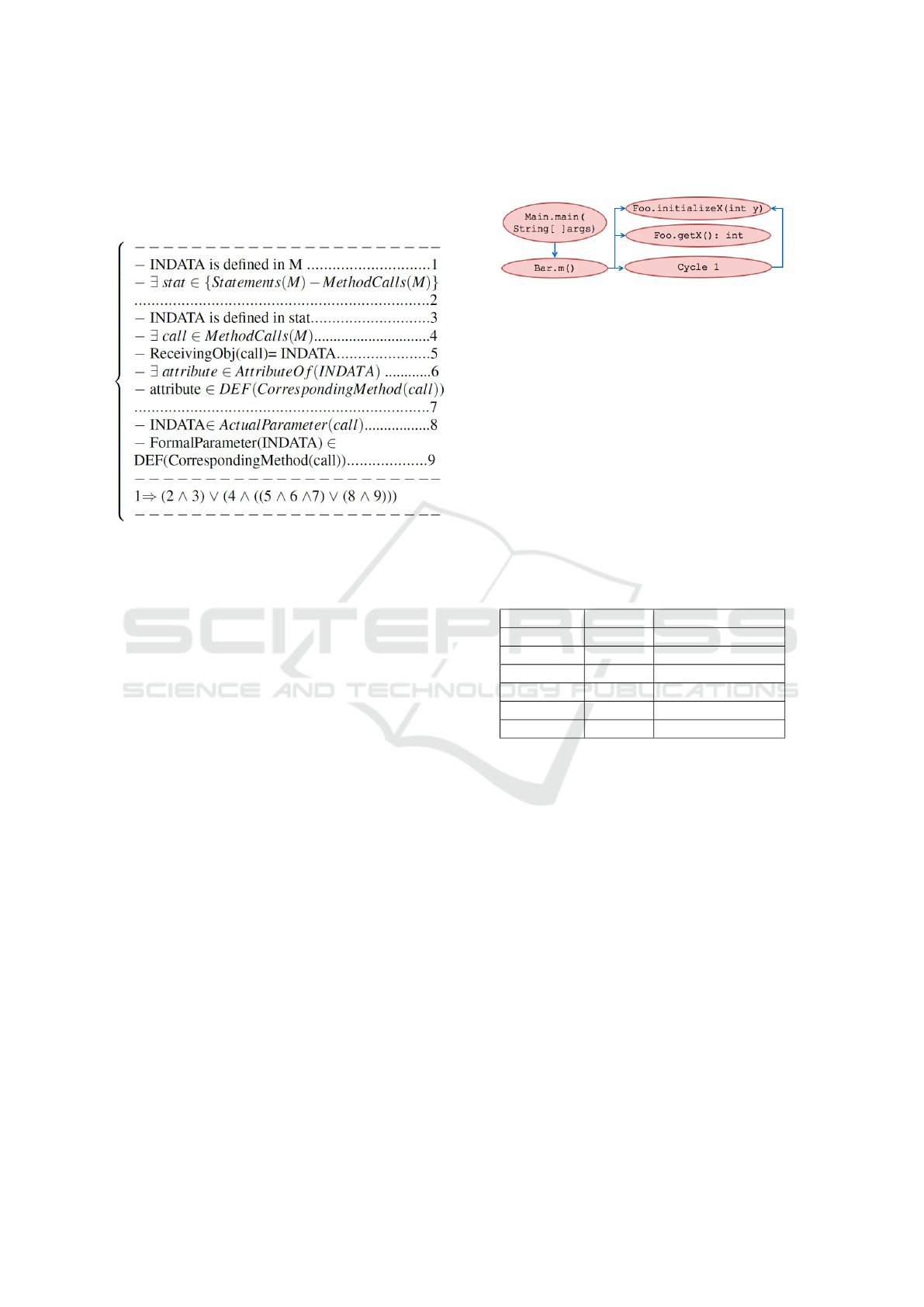
Figure 6: Acyclic call graph.
In the presence of direct or indirect recursion, the
call graph contains cycles, and hence it is not possible
to determine an order. To tackle this problem, each
cycle in the graph is replaced by a representative node
allowing the definition of a total order. The call graph
nodes are then analyzed following this order. If a node
represents a method, then DEF and USE sets are com-
puted using the former constraints. If the node is a re-
presentative, DEF and USE sets of each method in the
cycle represented by this node are computed, firstly,
without considering calls to the methods belonging to
the cycle, and then these sets are re-computed while
taking into account the calls between the methods of
the cycle.
Table 1: DEF/USE sets of the methods shown in Listing 1.
Method DEF set USE set
initializeX {x} {y}
getX
/
0 {x}
setX {x} {x, y, isDifferent}
incX {x} {x, y}
m {foo} {foo}
main {bar} {bar}
For example, to compute DEF and USE sets of
the methods shown in Listing 1, the cycle containing
methods setX and incX is replaced with a represen-
tative node (see Figure 6) allowing the definition of
the following order: 1) Foo.initializeX, 2) Foo.getX,
3) Cycle1, 4) Bar.m and 5)Main.main. Table 1 shows
DEF and USE sets computed for these methods.
4 CONTROL AND DATA FLOWS
RECOVERY
4.1 Control Flow Recovery
The recovery of workflow requires to build the corre-
sponding control flow. This later describes the exe-
cution order of tasks. The control flow of composite
ones describes the execution order of their enclosed
tasks. In our approach, we represent a control flow as
a graph, i.e. a Control Flow Graph (CFG). A CFG is
Refactoring Object-Oriented Applications for a Deployment in the Cloud
117
a graph where a node represents either a method call,
a predicate or a control. A predicate specifies a condi-
tion used in a control statement such as if statement.
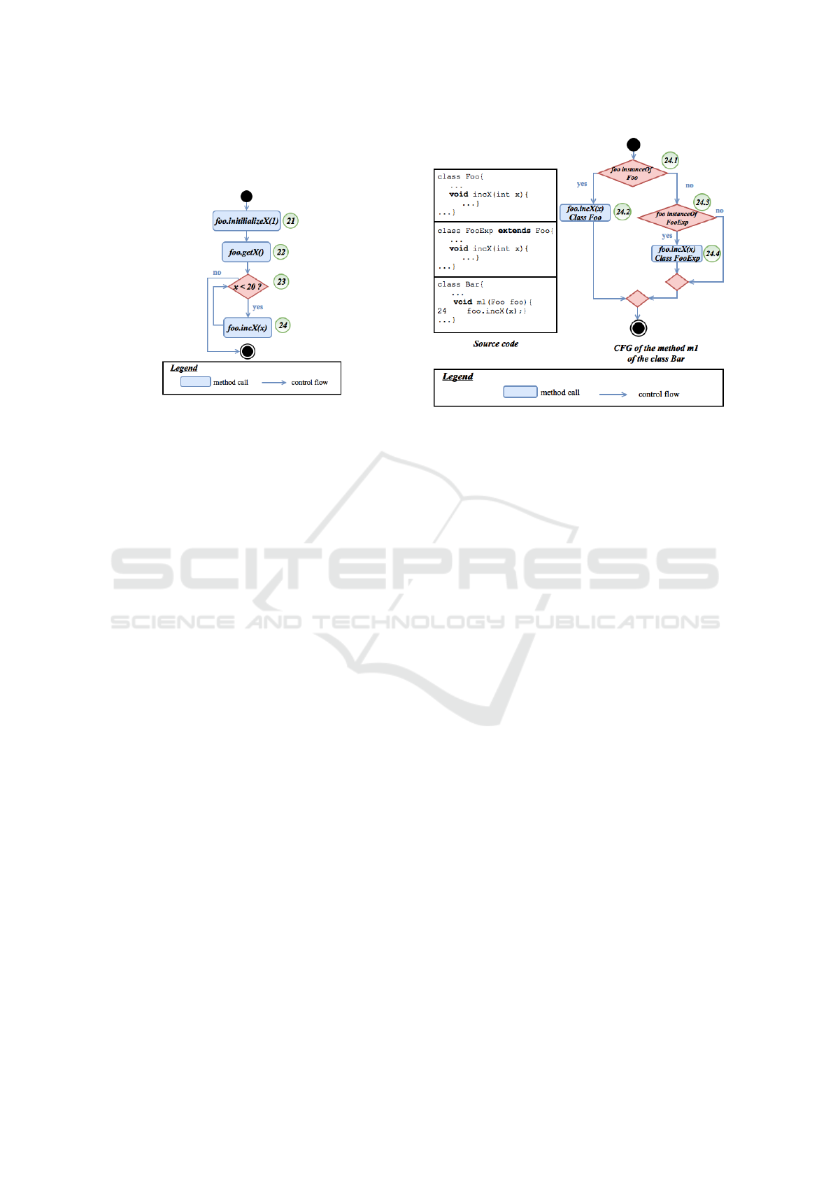
Figure 7: The CFG corresponding to the task mapped to
the method m of the class Foo shown in Listing 1.
Each node representing a method call or a predi-
cate is labeled based on its line number in the source
code. Edges of the CFG indicates the execution order
of method calls and evaluation of predicates.
A CFG is built incrementally by traversing the sta-
tements, which represents the body of the correspon-
ding method to this task (see Figure 7).
In the CFG, a node can represent a method call. If
the latter is dynamically dispatched, the exact method
to call can not be resolved statically (at compile time).
To be able to build a CFG statically, our idea is to re-
factor each dynamically dispatched call by replacing
it with nested if-then statements. In these statements,
conditions represent the possible run-time types of the
receiving object of the call, while the branches are
the different implementations of the called method in
each possible receiving object type. Figure 8 shows
an example of a CFG recovered in the presence of
dynamically dispatched calls. The method m1 of the
class Bar invokes the method incX of the class Foo
or the class FooExp. Hence, the corresponding CFG
contains a path for each possible run-time type of the
receiver.
4.2 Data Flow Recovery
In addition to the identification of the tasks and their
inputs/outputs (see Section 3.3), the construction of
a workflow also requires the identification of depen-
dency links between the data of these tasks (i.e. which
output data of a task represents an input data of anot-
her one). These dependency links constitute the data
flow. We present a data flow as a graph, a Data Flow
Graph (DFG) which have the same nodes of a CFG.
However, an edge is created between two nodes N
i
Figure 8: Example a CFG recovered in the presence of
dynamic binding.
and N
j
if a variable v defined in N
i
is used in N
j
. This
edge is then labeled using the name of the variable v
(see Figure 9).
It should be noted that a composite task encloses
other primitive and composite ones.Thus, a data flow
is recovered for each composite task so as to deter-
mine data dependencies between its enclosed tasks.
To build a DFG for a composite task, we compute
def-use triplets for the method mapped to this task.
Each triplet (var, def, use) specifies respectively the
name of a variable, the line number at which this va-
riable is defined and the line number at which it is
used. As explained in section 4.1, CFG nodes are la-
beled based on the corresponding line numbers in the
program. Hence, a data flow edge is created between
two nodes denoted by k and l if a def-use triplets (v, k,
l) exists.
For example, in Figure 9 an edge is created bet-
ween nodes denoted by 21 and 22 due to the existence
of a triplet (foo,21,22). In the rest of this section, the
process of computing def-use triplets is explained in
details.
4.2.1 Computing Def-Use Triplets
Computing def-use triplets is performed in three
steps. The first step allows to compute VarUsed sets.
It consists in determining variables used in each CFG
node. The goal of the second step is to compute Re-
achDef sets. It is the specification of definitions that
reach each node of the CFG. A definition of a varia-
ble v in a node N
i
, denoted (v,N
i
), reaches a node N
j
if
there is a path in the CFG between N
i
and N
j
without
a redefinition of v. In the third step, def-use triplets
are computed using VarUsed and ReachDef sets.
ENASE 2018 - 13th International Conference on Evaluation of Novel Approaches to Software Engineering
118
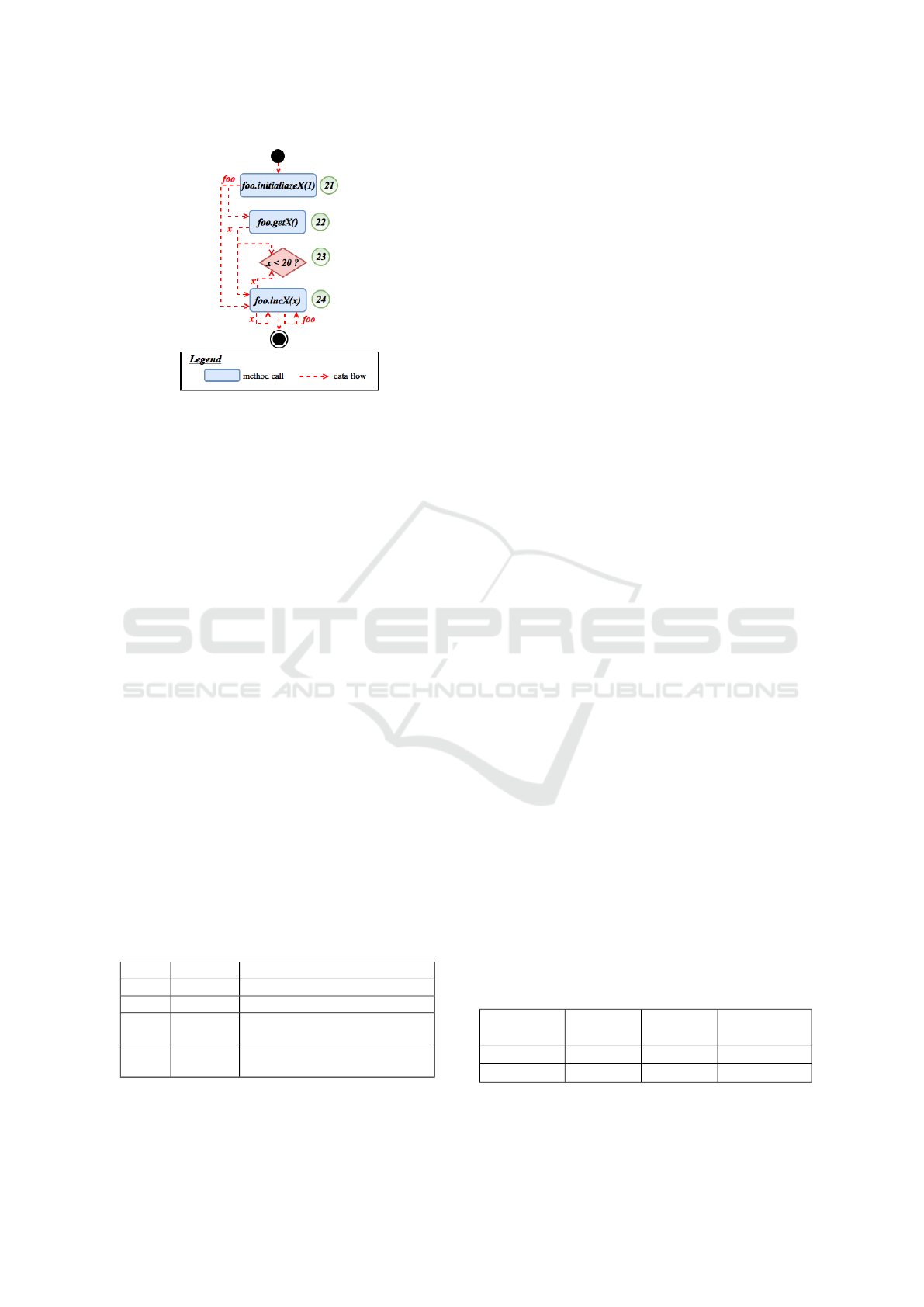
Figure 9: The DFG corresponding to the task mapped to
the method m of the class Foo shown in Listing 1.
Step1: Computing VarUsed Set: in order to
compute the VarUsed sets, first we compute DEF and
USE sets (see section 3.3.1 ). For each node in the
CFG representing a method call, the receiving object
is used if at least one of its attributes is in the USE
set of the invoked method. An effective parameter is
used if its corresponding formal parameter is in the
USE set of the invoked method. The VarUsed of a
predicate node contains variables which are used in
the corresponding expression.
Step2: Computing ReachDef Set: to determine
reaching definitions, first we compute DEF sets, i.e.
definitions produced by each node. For each node in
the CFG that represents a method call, the receiving
object is considered as defined if at least one of its
attributes is in the DEF set of the invoked method.
An effective parameter is considered as defined if its
corresponding formal parameter is in the DEF set of
the invoked method.
Once definitions produced by each node are spe-
cified, reaching definition are determined using the
propoagation algorithm proposed by Aho Alfred et al.
(Aho Alfred et al., 1986).
Step3: Computing Def-Use Triplets: for each
CFG node N, a triplet (v,def,N) is constructed if v ∈
VarUsed(N) and (v,def) ∈ ReachDef(N).
Table 2: VarUsed and ReachDef computed for each node of
the CFG shown in Figure 7.
Node VarUsed
ReachDef
21
/
0
/
0
22 {foo}
{(foo, 21)}
23 {x}
{(foo, 21), (foo,24), (x,22),
(x,24)}
24 {x,foo}
{(foo, 21), (foo,24), (x,22),
(x,24)}
For example, using VarUsed and ReachInDef
sets (see Table 2) computed for each node of the
CFG shown in Figure 7, def-use triplets constructed
are (foo,21,22), (foo,21,24), (foo,24,24), (x,22,23),
(x,22,24), (x,24,24) and (x,24,23).
5 WORKFLOW
IMPLEMENTATION
In the previous sections, we showed how elements of
the workflow mapping an OO application can be iden-
tified. In order to be able to execute the workflow,
we present in this section the workflow implementa-
tion. The corresponding implementation model is re-
presented in Figure 10. In this model each task is an
instance of the class Task. It has a list of input data
and a list of output data. To execute a task, we need to
invoke the method run on the corresponding instance.
If a task is primitive, the method run initializes
inputs and invokes the method mapped to this task.
Otherwise, instances corresponding to the elements
of the composite task are created and their methods
run are executed. These elements can be either con-
trol constructs or other tasks. The order of execution
of these elements is defined by the attribute task tas-
kSubelements.
Similarly, to run a control construct (if construct
or while construct), an instance corresponding to this
construct is created and its run method is invoked.
The run method initializes control construct inputs
and evaluates its condition. For example, in the case
of while construct, if the condition is true then instan-
ces corresponding to the elements of the list whileEle-
ments are created and their run methods are executed.
6 EXPERIMENTATION AND
VALIDATION
6.1 Data Collection
As a proof of concept of the proposed refactoring pro-
cess, we performed a case study on two applications.
Table 3 provides insight into the nature of the used
applications in our case study.
Table 3: Applications characteristics.
Application
name
No of
classes
No of
methods
No of lines
of code
eLib 9 80 555
PostOffice 6 57 231
eLib application is a Java program that supports
the main functions operated in a library: 1) insert
Refactoring Object-Oriented Applications for a Deployment in the Cloud
119
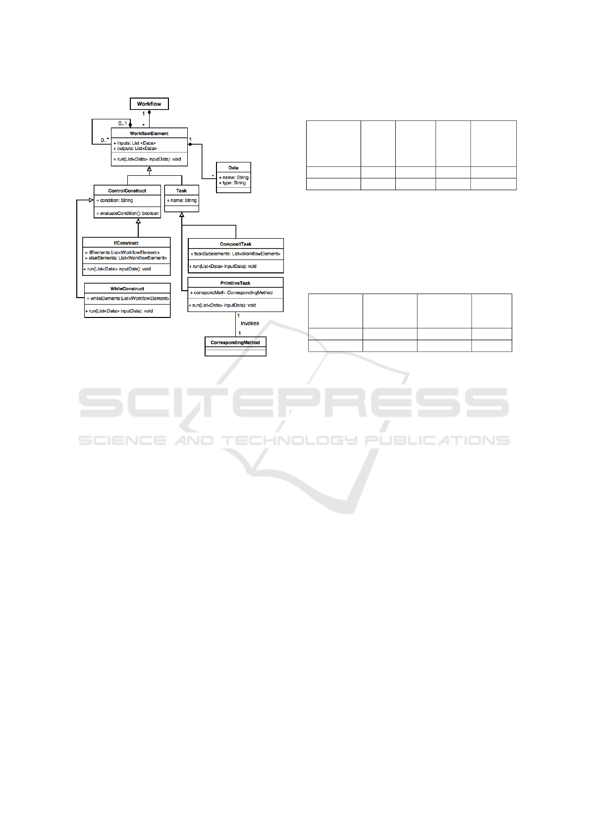
Figure 10: Workflow implementation model.
and remove of users/documents, search for users/do-
cuments and loan management. Its code is provided
in (Tonella and Potrich, 2005).
PostOffice application is also a Java program that
computes for each postal item its postage fee and its
reimbursement rate. In addition, it prints item infor-
mation. There are three types of postal items: letters,
parcels and express parcels.
6.2 Refactoring Results
We applied the workflow refactoring process on the
source code of each application in order to generate
the corresponding workflow.
As explained previously, the first step in our re-
factoring process is task identification which requires
applying extract method refactoring. Table 4 shows
the applications characteristics after applying extract
method refactoring using the built in functionality Ex-
tract method within eclipse IDE.
As we can notice, the number of methods after
applying extract method refactoring increased by an
average of 27,15% with a standard deviation of 16,61.
This can be explained by the fact that new methods
were created depending on the number of fragments
to be extracted, i.e. fragments consisting of state-
ments delimited by user method invocations that be-
long to the same block, in the application’source code.
Once the code is refactored, we analyze it to iden-
Table 4: Applications characteristics after applying extract
method refactoring.
Application No of
clas-
ses
No of
met-
hods
No of
lines
of
code
% of the
added
methods
eLib 9 115 788 43,75%
PostOffice 6 63 341 10,53%
tify tasks. Table 5 shows the results in term of number
of primitive and composite tasks for each application,
as well as the total number of identified tasks. This
total number equals the number of methods in the OO
application since each method is mapped to a task in
a workflow.
Table 5: Workflow refactoring results.
Application No of
primitive
tasks
No of
composite
tasks
Total
eLib 80 35 115
PostOffice 51 12 63
To demonstrate that the code of the generated
workflow preserves the semantic of the original one,
we executed both the code corresponding to this
workflow and the one corresponding to the analy-
zed OO application based on the same test suite. We
found out that the produced results are the same.
6.3 Threats to Validity
6.3.1 Threats to Internal Validity
There are four aspects to be considered regarding the
internal validity. These are as follows:
1. Control flow recovery from OO source code in the
presence of polymorphism and dynamic binding
requires taking into account all the possible run-
time types of a receiver, as explained in section
4.1. Therefore, if a method contains N virtual
calls and each one have M run-time types of a re-
ceiver, the CFG will contain at least N*M paths.
Hence, the scalability of our approach is not assu-
red. As a solution, we count to combine dynamic
and static analysis. Dynamic analysis is used to
determine the exact run-time type of a receiver,
while static analysis collect the rest of informa-
tion, i.e. methods, parameters, etc.
2. In our case studies, we constructed CFGs without
considering exception-handling. This requires to
extend our control flow recovery method to be
able to handle implicit transfers related to excep-
tion raising.
ENASE 2018 - 13th International Conference on Evaluation of Novel Approaches to Software Engineering
120

3. The presence of aliasing does not affect the ap-
plicability of our approach. The only requirement
for our data flow recovery in the presence of alias
is the availability of some alias analysis (Clarke
et al., 2013).
4. In our approach, we used Extract method refac-
toring to restructure code. However, the state-
ments to be extracted are not functionally related.
As a perspective, we will restructure the code to
obtain methods that have a purpose (Charalampi-
dou et al., 2016) (Kaya and Fawcett, 2016) (Kaya
and Fawcett, 2013).
6.3.2 Threats to External Validity
There are two aspects to be considered regarding the
external validity. These are as follows:
1. The approach was experimented on applications
implemented using Java programming language.
However, OO languages (e.g., C++, C#, etc) have
the same structure.
2. Only two case studies have been collected in the
experimentation. Hence, the approach needs to be
validated with a large number of case studies.
7 RELATED WORKS
Zou et al. (Zou et al., 2004) proposed an approach
to recover a workflow from the source code of an e-
commerce application. In order to recover this work-
flow, the authors identified a set of mapping rules that
associates workflow entities to source code entities.
However, applying these mapping directly will pro-
bably generate a workflow that contains a large num-
ber of irrelevant entities that do not map to any enti-
ties in the as-specified workflow. To tackle this pro-
blem, the authors proposed a set of heuristics to re-
duce the entities that have been selected. In (Zou
and Hung, 2006), Zou et al. proposed an ameliora-
tion to their recovery process in order to automate the
mapping between source code entities and business
process entities. They propose to lift the abstraction
level of the extracted control flow because it usually
contains more programming language specific control
constructs, for example checking whether a variable is
null.
In addition to previous works that are related to
workflow extraction, other works suggested to reverse
engineer others abstract models by analyzing source
code. In fact, reverse engineering of OO source code
have been widely studied in literature. The aim is to
generate models which allow the understanding of the
structure, such as class diagrams (Budhkar and Go-
pal, 2011), and behavior, like activity diagrams, inte-
raction diagrams and workflows.
Several tools have been developed to recover an
activity diagram from source code. Kosower and
Lopez-Villarejo (Kosower and Lopez-Villarejo, 2015)
proposed a tool, named Flowfen, to generate a set of
interconnected activity diagrams from annotated C++
code. Each diagram represents a method in the source
code. In order to recover these diagrams, the aut-
hors proposed that developers annotate the C++ code.
Mainly, the annotations are used to: specify the sta-
tement or the sequence of statements that represents
an activity, specify controlling conditions and return
value in a human readable way. The tool uses annota-
tions along with control structures to provide activity
diagrams.
Korshunova et al. (Korshunova et al., 2006) pro-
posed a reverse engineering tool, named CPP2XMI,
which allows extracting UML class, sequence, and
activity Diagrams in XMI format from C++ source
code. However, the recovery process of these dia-
grams had not been explained in details.
In our work, we use the Def-use triplets con-
struction. This technique has been widely used in
literature (Chen and Kao, 1999; Buy et al., 2000;
Martena et al., 2002). For example, Chen and Kao
(Chen and Kao, 1999) proposed an approach to con-
struct two types of def-use triplets: 1) intra-method
def-use triplets in which the definition and the use of
a variable are in the same method and 2) inter-method
def-use triplets in which the definition and the use of a
variable are in different methods. The def-use triplets
constructed in our approach are intra-method def-use
triplets because we are interested in determining data
dependencies between the sub-tasks of each compo-
site task, and not between sub-tasks of different com-
posite tasks.
Buy et al. (Buy et al., 2000) identified def-use
triplets for a single class. Each triplet specifies the
method that defines and the one that uses the same at-
tribute. However, their approach works only on scalar
attributes. Martena et al. (Martena et al., 2002) ex-
tended this approach so as to handle attributes even
if they are objects. Their idea is to classify methods
of each class in three categories: modifier, user and
user-modifier, based on whether a method defines an-
d/or uses class attributes. When a method is invoked
on an object, using this classification, it is possible to
determine only whether the object is defined and/or
used.
Compared to existing approaches, we proposed
a fully automatic approach that generates a work-
flow, unlike the one proposed by Kosower and Lopez-
Refactoring Object-Oriented Applications for a Deployment in the Cloud
121

Villarejo (Kosower and Lopez-Villarejo, 2015). Their
approach needs human interactions to add annotations
which is not an easy task. Especially for large appli-
cations, containing millions of lines of code. Moreo-
ver, the generated workflow can be executed contrary
to the workflow produced by Zou and al (Zou et al.,
2004) which can be used as a documentation only. It
is worthy to note that due to the fact that the gene-
rated workflow has a hierarchical structure, it can be
used for documentation as well. It is up to the one
using it (e.g. developer, architect, etc.) to decide at
which level of details he wants to stop. In addition,
unlike the workflow produced by Zou and al (Zou
et al., 2004), data dependencies between tasks are ex-
plicitly expressed in our workflow. To the best of our
knowledge, only our approach recovers both data and
control flows from source code.
Note that, several works rely on workflows in or-
der to perform dynamic configuration to optimize re-
sources usage in the cloud, and thus to reduce exe-
cution costs (Zhu et al., 2016; Masdari et al., 2016;
Fakhfakh et al., 2014; Xu et al., 2009; Lin and Lu,
2011). In our future works, we intend either to use
these works to run the generated workflow or to pro-
pose a new approach inspired from them.
8 CONCLUSION
The main contribution of the work presented in this
paper is the refactoring of OO source code to gene-
rate a workflow. For this purpose, first a mapping mo-
del between OO programming concepts and workflow
concepts was defined. In order to identify the map-
ping, a three steps process was proposed. It is worthy
to note that the generated workflow can be used to de-
ploy code and data on paying platforms such as the
cloud and reducing execution costs. As a part of fu-
ture work, we plan to apply our approach on real and
complex case studies. In addition to this, we intend
to improve the generated workflow by enhancing the
granularity level of the identified tasks. In fact, some
of them are fin-grained. Finally, we plan to propose an
approach to run the generated workflow on the cloud
while reducing costs.
REFERENCES
Aho Alfred, V., Ravi, S., and Ullman Jeffrey, D. (1986).
Compilers: principles, techniques, and tools. Rea-
ding: Addison Wesley Publishing Company.
Bass, L. (2007). Software architecture in practice. Pearson
Education India.
Budhkar, S. and Gopal, A. (2011). Reverse engineering java
code to class diagram: An experience report. Inter-
national Journal of Computer Applications, 29(6):36–
43.
Buy, U., Orso, A., and Pezze, M. (2000). Automated testing
of classes. In ACM SIGSOFT Software Engineering
Notes, volume 25, pages 39–48. ACM.
Charalampidou, S., Ampatzoglou, A., Chatzigeorgiou, A.,
Gkortzis, A., and Avgeriou, P. (2016). Identifying
extract method refactoring opportunities based on
functional relevance. IEEE Transactions on Software
Engineering.
Chen, M.-H. and Kao, H. M. (1999). Testing object-
oriented programs-an integrated approach. In Soft-
ware Reliability Engineering, 1999. Proceedings.
10th International Symposium on, pages 73–82. IEEE.
Clarke, D., Wrigstad, T., and Noble, J. (2013). Aliasing
in Object-oriented Programming: Types, Analysis and
Verification, volume 7850. Springer.
Dillon, T., Wu, C., and Chang, E. (2010). Cloud compu-
ting: issues and challenges. In Advanced Information
Networking and Applications (AINA), 2010 24th IEEE
International Conference on, pages 27–33. Ieee.
Espadas, J., Molina, A., Jim
´
enez, G., Molina, M., Ram
´
ırez,
R., and Concha, D. (2013). A tenant-based resource
allocation model for scaling software-as-a-service ap-
plications over cloud computing infrastructures. Fu-
ture Generation Computer Systems, 29(1):273–286.
Fakhfakh, F., Kacem, H. H., and Kacem, A. H. (2014).
Workflow scheduling in cloud computing: A sur-
vey. In Enterprise Distributed Object Computing Con-
ference Workshops and Demonstrations (EDOCW),
2014 IEEE 18th International, pages 372–378. IEEE.
Garlan, D. and Shaw, M. (1993). An introduction to soft-
ware architecture. Advances in software engineering
and knowledge engineering, 1(3.4).
Hollingsworth, D. (1995). Workflow management coali-
tion: The workflow reference model.
Kaur, N., Aulakh, T. S., and Cheema, R. S. (2011). Com-
parison of workflow scheduling algorithms in cloud
computing. International Journal of Advanced Com-
puter Science and Applications, 2(10).
Kaya, M. and Fawcett, J. W. (2013). Identifying extract
method opportunities based on variable references (s).
In SEKE, pages 153–158.
Kaya, M. and Fawcett, J. W. (2016). Identification of extract
method refactoring opportunities through analysis of
variable declarations and uses. International Journal
of Software Engineering and Knowledge Engineering,
pages 1–21.
Korshunova, E., Petkovic, M., Van Den Brand, M., and
Mousavi, M. R. (2006). Cpp2xmi: reverse engi-
neering of uml class, sequence, and activity diagrams
from c++ source code. In Reverse Engineering, 2006.
WCRE’06. 13th Working Conference on, pages 297–
298. IEEE.
Kosower, D. A. and Lopez-Villarejo, J. J. (2015). Flowgen:
Flowchart-based documentation for c++ codes. Com-
puter Physics Communications, 196:497–505.
ENASE 2018 - 13th International Conference on Evaluation of Novel Approaches to Software Engineering
122

Lin, C. and Lu, S. (2011). Scheduling scientific workflows
elastically for cloud computing. In Cloud Computing
(CLOUD), 2011 IEEE International Conference on,
pages 746–747. IEEE.
Martena, V., Orso, A., and Pezze, M. (2002). Interclass
testing of object oriented software. In Engineering of
Complex Computer Systems, 2002. Proceedings. Eig-
hth IEEE International Conference on, pages 135–
144. IEEE.
Masdari, M., ValiKardan, S., Shahi, Z., and Azar, S. I.
(2016). Towards workflow scheduling in cloud com-
puting: A comprehensive analysis. Journal of Net-
work and Computer Applications, 66:64–82.
Mell, P., Grance, T., et al. (2011). The nist definition of
cloud computing.
Russell, N., Ter Hofstede, A. H., Van Der Aalst, W. M., and
Mulyar, N. (2006). Workflow control-flow patterns: A
revised view. BPM Center Report BPM-06-22, BPM-
center. org, pages 06–22.
Taylor, R. N., Medvidovic, N., and Dashofy, E. M.
(2009). Software architecture: foundations, theory,
and practice. Wiley Publishing.
Tonella, P. and Potrich, A. (2005). Reverse Engineering
of Object Oriented Code. Monographs in Computer
Science. Springer.
Wu, Z., Liu, X., Ni, Z., Yuan, D., and Yang, Y. (2013).
A market-oriented hierarchical scheduling strategy in
cloud workflow systems. The Journal of Supercompu-
ting, pages 1–38.
Xu, M., Cui, L., Wang, H., and Bi, Y. (2009). A multiple
qos constrained scheduling strategy of multiple work-
flows for cloud computing. In Parallel and Distributed
Processing with Applications, 2009 IEEE Internatio-
nal Symposium on, pages 629–634. IEEE.
Zhu, Z., Zhang, G., Li, M., and Liu, X. (2016). Evoluti-
onary multi-objective workflow scheduling in cloud.
IEEE Transactions on Parallel and Distributed Sys-
tems, 27(5):1344–1357.
Zou, Y. and Hung, M. (2006). An approach for extracting
workflows from e-commerce applications. In Pro-
gram Comprehension, 2006. ICPC 2006. 14th IEEE
International Conference on, pages 127–136. IEEE.
Zou, Y., Lau, T. C., Kontogiannis, K., Tong, T., and Mc-
Kegney, R. (2004). Model-driven business process re-
covery. In Reverse Engineering, 2004. Proceedings.
11th Working Conference on, pages 224–233. IEEE.
Refactoring Object-Oriented Applications for a Deployment in the Cloud
123
