
Finite-Time Altitude and Attitude Tracking of a Tri-Rotor UAV using
Modified Super-Twisting Second Order Sliding Mode
Yassine Kali
1
, Jorge Rodas
2
, Maarouf Saad
1
, Khalid Benjelloun
3
, Magno Ayala
2
and Raul Gregor
2
1
´
Ecole de Technologie Sup
´
erieure, Quebec University, Montreal, QC H3C 1K3, Canada
2
Laboratory of Power and Control Systems, Facultad de Ingenier
´
ıa, Universidad Nacional de Asunci
´
on, Paraguay
3
A2I Laboratory, Ecole Mohammadia d’Ing
´
enieurs, Mohammed V University, Rabat, Morocco
Keywords:
Altitude Tracking, Attitude Tracking, Finite-time Convergence, Lyapunov, Unmanned Aerial Vehicle, Second
Order Sliding Mode, Super-twisting Algorithm, Uncertainties.
Abstract:
This paper presents the problem of robust altitude and attitude trajectory tracking of a tri-rotor Unmanned Ae-
rial Vehicle (UAV) based on a finite-time second order sliding mode control algorithm. The chosen algorithm
is a modified super-twisting control with double closed-loop feedback regulation that provides fast finite-time
convergence even when the system trajectories are far from the sliding surface, robustness against a wide class
of uncertainties and disturbances. Moreover, this algorithm eliminates the major disadvantage of the classical
sliding mode, the well-known chattering phenomenon. The stability analysis of the closed-loop system and
the convergence time are given based on a strong Lyapunov function. To show the effectiveness of the used
method, simulation results of different scenarios are presented for the considered tri-rotor UAV.
1 INTRODUCTION
In recent years, control of aerial robots have become
a coveted field of research. In fact, Unmanned Aerial
Vehicles (UAVs) are increasingly used in numerous
applications such as construction, visual inspection,
exploration, transportation and others (Nex and Re-
mondino, 2014; Sankaran et al., 2015; Segales et al.,
2016; Singh and Frazier, 2018). Apart from the fact
that UAVs are highly underactuated systems, as all
nonlinear systems, they are suffering from uncertain-
ties due to the variation of the inertia and mass (Yang
and Xian, 2017) (e.g.: the case of transportation) and
external disturbances due to environmental variations
as wind (Pflimlin et al., 2004; Ceccarelli et al., 2007)
(e.g.: the case of outdoor scenarios)
In literature, several nonlinear controllers have
been designed for the problem of tracking and/or
stabilization of UAVs such as feedback lineariza-
tion (Voos, 2009; Zhou et al., 2010), backstep-
ping (Ahmed et al., 2006; Lee et al., 2013), Sliding
Mode Control (SMC) (Runcharoon and Srichatrapi-
muk, 2013) and others. Among these controllers, the
best promising one is SMC which is famous for its
insensitivity to a wide class of uncertainties and dis-
turbances, its simplicity of design and its finite-time
convergence property (Utkin et al., 1999). SMC uses
discontinuous control inputs to force the system tra-
jectories to converge to the user-chosen sliding sur-
face. Nevertheless, to ensure all these good features,
the discontinuous signals must be high which cause
the chattering phenomenon (Fridman, 2001; Boiko
and Fridman, 2005). This phenomenon is conside-
red the major drawback of which SMC suffers from.
Consequently, the desired performances might be re-
duced and the system actuators cannot deal with the
chattering frequency and might be degraded.
To solve this problem, many works have been de-
veloped and published (Lee et al., 2009; Tseng and
Chen, 2010; Besnard et al., 2012; Kali et al., 2015).
The most popular one for second order systems is
the Second Order Sliding Mode (SOSM) introduced
in (Levant, 2003). The concept of SOSM is to make
the discontinuous signal acting on the derivative of the
control input signal, hence, the control input becomes
continuous (Kali et al., 2017b; Kali et al., 2017c).
SOSM has been extensively used for UAVs (Be-
nallegue et al., 2008; Zheng et al., 2014; Davila and
Salazar, 2017; Munoz et al., 2017a; Munoz et al.,
2017b). However, this method requires some infor-
mations (e.g.: first time derivative of the sliding sur-
face) that are often not available for measurements.
Kali, Y., Rodas, J., Saad, M., Benjelloun, K., Ayala, M. and Gregor, R.
Finite-Time Altitude and Attitude Tracking of a Tri-Rotor UAV using Modified Super-Twisting Second Order Sliding Mode.
DOI: 10.5220/0006861904350442
In Proceedings of the 15th International Conference on Informatics in Control, Automation and Robotics (ICINCO 2018) - Volume 1, pages 435-442
ISBN: 978-989-758-321-6
Copyright © 2018 by SCITEPRESS – Science and Technology Publications, Lda. All rights reserved
435
As a solution to this limitation, the Super-Twisting
Algorithm (STA) has been proposed (Guzm
´
an and
Moreno, 2015; Gonz
´
alez-Hern
´
andez et al., 2017b;
Gonz
´
alez-Hern
´
andez et al., 2017a; Ibarra and Cas-
tillo, 2017; Kali et al., 2017a; Kali et al., 2018a; Kali
et al., 2018b). Indeed, apart from that STA ensures ro-
bustness, finite-time converge and chattering elimina-
tion, it does not require the measurements of the first
time derivative of the sliding surface. However, when
the system trajectories are far from the selected swit-
ching surface, the convergence becomes slow (Mo-
reno, 2014) which is not desirable for fast robotic sy-
stems.
In order to improve the convergence speed, a mo-
dified STA with double closed-loop feedback regula-
tion has been proposed (Yang and Xian, 2017). The
proposed algorithm was tested on a DC servo system.
The obtained results were satisfactory in comparison
with different proposed STA structures. To the aut-
hors’ best knowledge, this structure has never been
used for a tri-rotor UAV system. In this paper, this
algorithm will be derived for the altitude and attitude
tracking of an uncertain tri-rotor UAV system.
The rest of this paper is organized into four secti-
ons as follows. In the next section, the conside-
red tri-rotor UAV is described and its altitude and
attitude model are given. In Section 3, the modi-
fied STA with double closed-loop feedback regula-
tion is designed for the problem of altitude and atti-
tude tracking in presence of uncertainties and its sta-
bility analysis is proved using the Lyapunov method.
In section 4, simulation results on the considered tri-
rotor UAV are given to demonstrate the effectiveness
of the used STA with double closed-loop feedback re-
gulation. The conclusion is given in the fifth section.
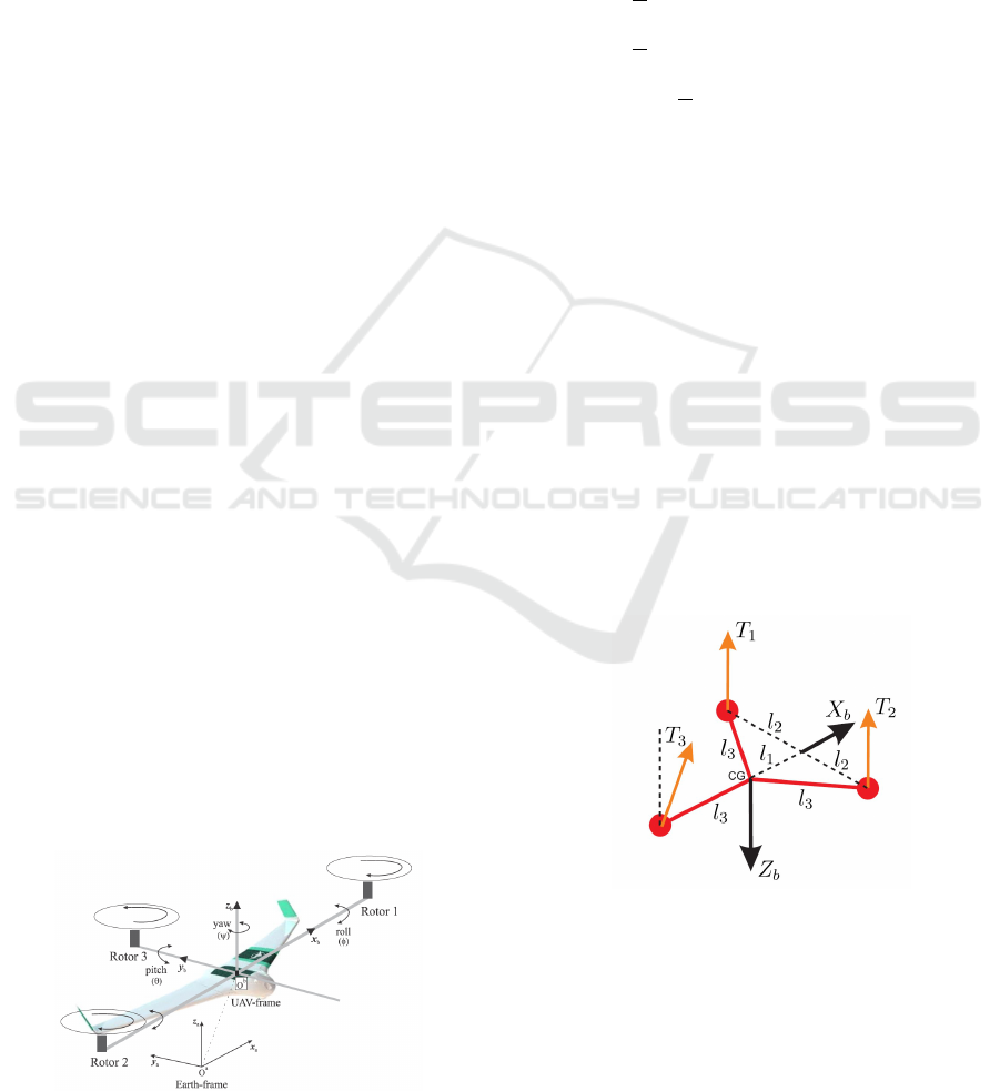
2 TRI-ROTOR UAV MODEL
The considered tri-rotor UAV system is shown in
Fig. 1. The main advantage of this kind of UAVs is
that they require fewer motors than the other propo-
sed multi-rotors UAV systems such as four-rotors or
Figure 1: Tri-rotor UAV.
six-rotors. This advantage allows a reduction in vo-
lume, weight and energy consumption. The two ro-
tors placed in the forward part of the tri-rotor rotate in
opposite direction with respect to the third rotor pla-
ced in the backward part.
2.1 Altitude Model
The altitude model of the considered tri-rotor can be
expressed by the following equation:
¨
X =
1
m
(sin(ψ)sin(θ)cos(φ) −cos(ψ)sin(φ))τ
1
(1)
¨
Y =
1
m
(cos(ψ)sin(θ)cos(φ) + sin(ψ)sin(φ))τ
1
(2)
¨
Z = −g +
1
m
cos(θ)cos(φ)τ
1
(3)
where m denotes the mass of the tri-rotor, g is the
constant of gravity, τ
1
is the collective or the vertical
force and φ, θ, ψ denote the Euler angles (roll φ, pitch
θ and yaw ψ).
2.2 Attitude Model
The attitude model of the considered tri-rotor can be
expressed by the following equation:
J W
¨
Θ + J
˙
W
˙
Θ +
W
˙
Θ ×J W
˙
Θ
= τ (4)
where Θ = [φ, θ, ψ]
T
are the Euler angles, τ =
[τ
φ
, τ
θ
, τ
ψ
]
T
represents the roll, pitch and yaw torques,
J = diag(I
x
, I
y
, I
z
) is the diagonal inertia matrix while
W is the Euler matrix. W and its first-time derivative
˙
W are defined by:
W =
1 0 −sin(θ)
0 cos(φ) cos(θ) sin(φ)
0 −sin(φ) cos(θ) cos(φ)
(5)
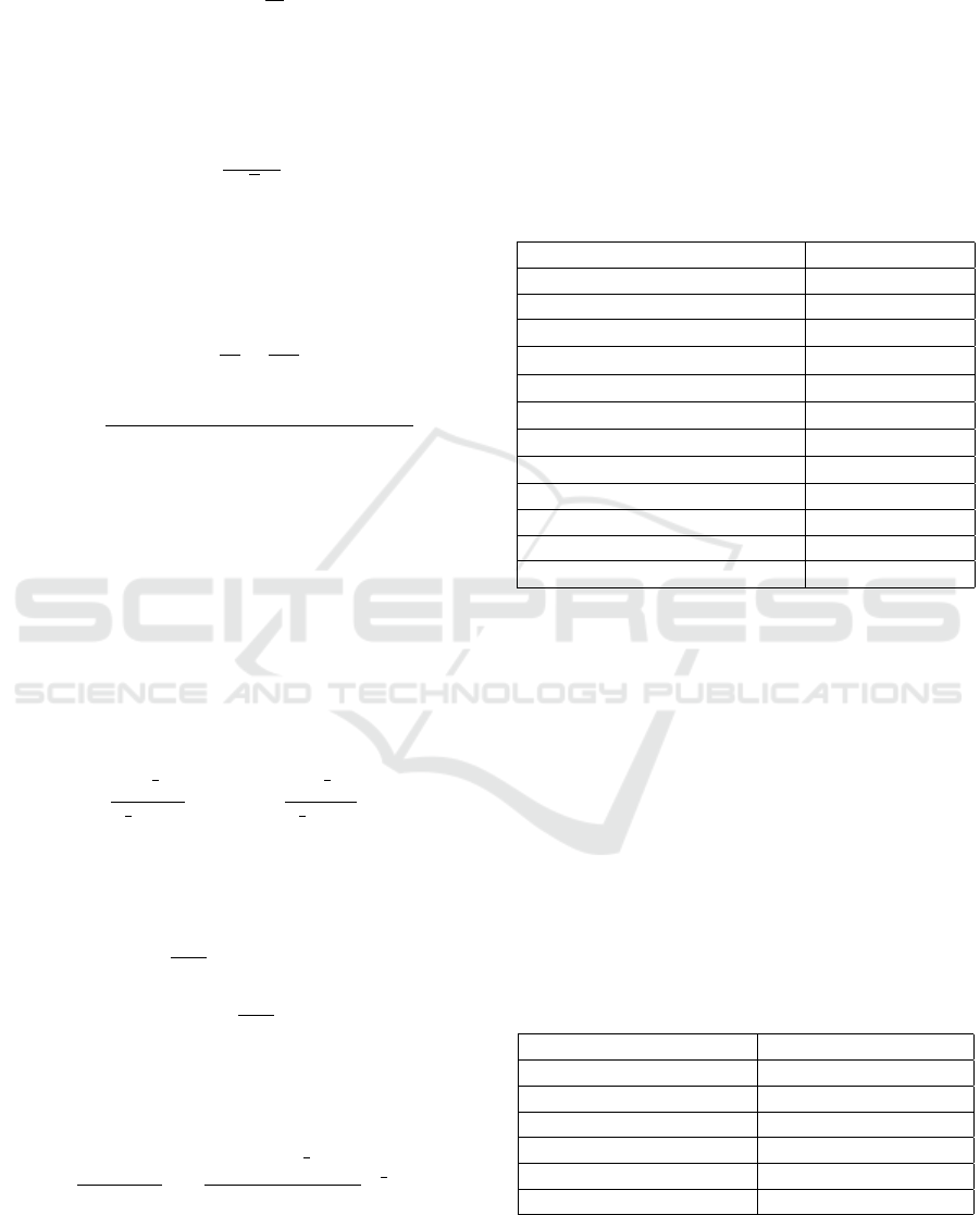
Figure 2: Reference system for the tri-rotor UAV.
Moreover, the control torque inputs can be expres-
sed as follows:
τ
φ
= l
2
( f
1
− f
2
) (6)
τ
θ
= −l
1
( f
1
+ f
2
) + l
3
f
3
cos(α) (7)
τ
ψ
= −l
3
f
3
sin(α) (8)
τ
1
= f
1
+ f
2
+ f
3
cos(α) (9)
ICINCO 2018 - 15th International Conference on Informatics in Control, Automation and Robotics
436

where α represents the tilting angle of the third ro-
tor placed in the backward part, f
i
for i = 1, 2, 3 is
the thrust generated by the rotor i, l
i
for i = 1, 2, 3
are given in Fig. 2. The control torque inputs given
by (6), (7), (8) and (9) can be written in a matrix form
as follows:
τ
1
τ
φ
τ
θ
τ
ψ
=
1 1 cos(α)
l
2
−l
2
0
−l
1
−l
1
l
3
cos(α)
0 0 −l
3
sin(α)
| {z }
F
f
1
f
2
f
3
3 MODIFIED SUPER-TWISTING
In this section, the proposed second order sliding
mode controller based on a modified STA for the
finite-time altitude and attitude tracking of the con-
sidered tri-rotor UAV will be designed. The control
objective is to ensure that the altitude and attitude po-
sitions defined by Z, φ, θ, ψ track with high precision
even in presence of uncertainties and disturbances the
bounded desired trajectories Z
d
, φ
d
, θ
d
, ψ
d
.
Now, let us introduce x = [x
T
1
, x
T
2
]
T
as state va-
riables with x
1
= [Z, φ, θ, ψ]
T
and x
2
= [
˙
Z,
˙
φ,
˙
θ,
˙
ψ]
T
.
Then, the equations of motion are given by:
˙x
1
= x
2
˙x
2
= f (x) + g(x)u + h(t)
(10)
Comparing the above equation with (4) gives the fol-
lowing equivalences:
f (x) =
−g
−(JW )
−1
J
˙
W
˙
Θ +
W
˙
Θ ×JW
˙
Θ
g(x) =
1
m
cos(θ)cos(φ) 0
1×3
0
3×1
(JW )
−1
u =
τ
1
τ
φ
τ
θ
τ
ψ
T
and h(t) ∈ R
4
denotes the uncertain
vector caused by the wind disturbances, unmodelled
dynamics.
In the following, the control law that will force
the system trajectories x
1
to track with high accuracy
the known desired trajectories x
1d
= [Z
d
, φ
d
, θ
d
, ψ
d
]
T
is designed based on the following assumptions:
• Assumption 1: The system trajectories x
1
and
their first-time derivative x
2
are available for mea-
surements.
• Assumption 2: The desired trajectories x
1d
and
their first and second time derivatives x
2d
, ˙x
2d
are
known, bounded and limited to:
−π
2
< φ
d
<
π
2
,
−π
2
< θ
d
<
π
2
, −π < ψ
d
< π.
• Assumption 3: The Euler angles (roll, pitch and
yaw) are limited to:
−π
2
< φ <
π
2
,
−π
2
< θ <
π
2
, −π < ψ < π.
Based on all these assumptions, the uncertain
functions h
i
(t) for i = 1, 2, 3, 4 are globally Lip-
schitz (Derafa et al., 2012):
˙
h
i
(t)
≤ δ
i
where δ
i
> 0 represents the Lipschitz constant.
Let e = x
1
−x
1d
∈ R
4
be the trajectory tracking
error. Then, the first step in the design procedure con-
sists on defining the sliding surface. In this paper, the
integral sliding surface is selected:
S = ˙e + K
p
e + K
I
Z
t
0
e dt (11)
where K
p
= diag(K
p1
, K
p2
, K
p3
, K
p4
) and K
I
=
diag(K
I1
, K
I2
, K
I3
, K
I4
) are diagonal positive definite
matrices. The first time derivative of the above in-
tegral sliding surface is computed using the nominal
model as follows:
˙
S = ¨e + K
p
˙e + K
I
e
= ˙x
2
− ¨x
1d
+ K
p
˙e + K
I
e
= f (x) + g(x) u − ¨x
1d
+ K
p
˙e + K
I
e
(12)
Hence, the modified super-twisting control algorithm
is obtained by resolving the following equation:
˙
S = −K
1
Λ(S) sign(S) −K
2
S + ϖ
˙
ϖ = −K
3
sign(S) −K
4
ϖ
(13)
where Λ(S) = diag
|S
1
|
0.5
, |S
2
|
0.5
, |S
3
|
0.5
, |S
4
|
0.5
,
K
1
= diag(K
11
, ··· , K
14
), K
2
= diag(K
21
, ··· , K
24
),
K
3
= diag(K
31
, ··· , K
34
) and K
4
= diag(K
41
, ··· , K
44
)
are diagonal positive matrices where the coeffi-
cients will be fixed in the stability analysis and
sign(S) = [sign(S
1
), sign(S
2
), ··· , sign(S
4
)]
T
with:
sign(S
i
) =
1, if S
i
> 0
0, if S
i
= 0
−1, if S
i
< 0
(14)
Theorem 3.1. If the modified STA gains are chosen
for i = 1, 2, 3,4 as:
K
1i
= γK
3i
, K
2i
= βK
4i
, K
4i
> 0
K
3i
> max{C1,C2}
(15)
with:
γ >
|β −2|
√
2β
, γ 6= 2, β > 0, δ
i
> 0
C1 =
δ
2
i
γβ
+
4
γ
3
β
Finite-Time Altitude and Attitude Tracking of a Tri-Rotor UAV using Modified Super-Twisting Second Order Sliding Mode
437

C2 =
32 + γ
3
β
2
+ −8γ
2
β + 8γ
2
δ
2
i
−4γ
3
δ
2
i
4γ
3
β(2 −γ)
Then, the modified super-twisting control algorithm
with double closed-loop feedback regulation for the
considered uncertain tri-rotor UAV (10) is given by:
u = −g(x)
−1
[ f (x) + v] (16)
where v is defined as:
v = −¨x
1d
+ K
p
˙e + K
I
e + K
1
Λ(S) sign(S) + K
2
S
+ K
3
Z
t
0
sign(S) dt −K
4
Z
t
0
ϖdt
(17)
ensures finite-time altitude and attitude trajectory
tracking.
Proof. The stability of the closed loop error
will be analyzed using the same methodology used
in (Guzm
´
an and Moreno, 2015). First of all, sub-
stituting the modified super-twisting control algo-
rithm (16) in the equation of motion (10) leads to:
˙
S = −K
1
Λ(S) sign(S) −K
2
S + ϖ
˙
ϖ = −K
3
sign(S) −K
4
ϖ +
˙
h(t)
(18)
The above closed-loop error dynamics can be decom-
posed into 4 sub-systems as:
˙
S
i
(t) = −K
1i
|S
i
|
0.5
sign(S
i
) −K
2
S
i
+ ϖ
i
˙
ϖ
i
= −K
3i
sign(S
i
) −K
4i
ϖ
i
+
˙
h
i
(t).
(19)
Now, let us consider the following candidate positive
definite Lyapunov function:
V = ξ
T
Lξ (20)
where ξ = [ξ
1i
ξ
2i
]
T
with ξ
1i
= |S
i
|
0.5
sign(S
i
) and
ξ
2i
= ϖ
i
and L is a symmetric positive definite ma-
trix. The Lyapunov function in (20) is positive defi-
nite, continuous and differentiable except when the
sliding surface is equal to zero S
i
= 0 and radially
bounded by choosing appropriate matrix L as:
L =
β +
2
γ
2
−
2
γ
−
2
γ
1
(21)
where γ > 0 and β > 0. To calculate the first-time deri-
vative of the Lyapunov function, we need to calculate
first the first-time derivative of the vector ξ. Remark
that |ξ
1i
| = |S
i
|
0.5
. Then,
˙
ξ = [
˙
ξ
1i
,
˙
ξ
2i
]
T
is as follows:
˙
ξ
1i
=
1
2|S
i
|
0.5
˙
S
i
, and
˙
ξ
2i
=
˙
ϖ
i
. (22)
Hence:
˙
ξ =
1
|ξ
1i
|
Aξ +
1
|ξ
1i
|
B
˙
h
i
(t)|ξ
1i
| (23)
where:
A =
−
1
2
(K
1i
+ K
2i
|ξ
1i
|)
1
2
−K
3i
−K
4i
|ξ
1i
|
, B =
"
0
1
#
Moreover, the first time derivative of the Lyapunov
function V is calculated as:
˙
V =
˙
ξ
T
(t)Lξ + ξ
T
L
˙
ξ (24)
Substituting
˙
ξ in
˙
V leads to:
˙
V =
1
|ξ
1i
|
ξ
T
A
T
L + LA
ξ +
2
˙
h
i
(t)
|ξ
1i
|
|ξ
1i
|B
T
Lξ
≤
1
|ξ
1i
|
ξ
T
A
T
L + LA
ξ +
˙
h
2
i
(t)|ξ
1i
|
2
+ ξ
T
LBB
T
Lξ
≤
1
|ξ
1i
|
ξ
T
A
T
L + LA + δ
2
i
C
T
C + LBB
T
L
ξ
≤ −ξ
T
Qξ
(25)
where C = [1 0]
T
. Considering that K
1i
= γK
3i
and
K
2i
= βK
4i
. Then, Q is calculated as follows:
Q = −
1
|ξ
1i
|
(A
T
L + LA + δ
2
i
C
T
C + LBB
T
L)
=
Q
11
Q
12
Q
21
Q
22
(26)
where:
Q
11
=
4β
γ
2
+ β
2
K
4i
+
1
|ξ
1i
|
γβK
3i
−δ
2
i
−
4
γ
2
Q
12
= Q
21
= −
2 + β
γ
K
4i
+
1
|ξ
1i
|
2
γ
−
β
2
Q
22
= 2K
4i
+
1
|ξ
1i
|
2
γ
−1
The above matrix Q can be splitted into two matrices
as follows:
Q = Q
1
+
1
|ξ
1i
|
Q
2
(27)
where
Q
1
=
4β
γ
2
+ β
2
K
4i
−
2+β
γ
K
4i
−
2+β
γ
K
4i
2K
4i
(28)
Q
2
=
γβK
3i
−δ
2
i
−
4
γ
2
2
γ
−
β
2
2
γ
−
β
2
2
γ
−1
(29)
Since Q
1
and Q
2
are symmetrical. Then, they are po-
sitive definite if the four following conditions are met:
4β
γ
2
+ β
2
K
4i
> 0 (30)
ICINCO 2018 - 15th International Conference on Informatics in Control, Automation and Robotics
438
det(Q
1
) > 0 (31)
αβK
3i
−δ
2
i
−
4
γ
2
> 0 (32)
det(Q
2
) > 0 (33)
The condition in equation (30) is always verified. The
inequality in (31) is met if:
γ >
|β −2|
√
2β
(34)
While the inequalities in equations (32) and (33) are
verified if:
K
3i
> max{C1,C2} (35)
with:
C1 =
δ
2
i
γβ
+
4
γ
3
β
C2 =
32 + γ
3
β
2
+ −8γ
2
β + 8γ
2
δ
2
i
−4γ
3
δ
2
i
4γ
3
β(2 −γ)
Therefore, verifying the conditions above,
˙
V is nega-
tive definite. Hence, the stability of the closed-loop is
proven.
To prove the finite-time convergence, let us recall
the fact that the Lyapunov function is radially boun-
ded. Then:
λ
min
{L}kξk
2
2
≤V ≤ λ
max
{L}kξk
2
2
(36)
with λ
min
{L} and λ
max
{L} denote respectively the
minimum and maximum eigenvalues of the matrix L
and kξk
2
2
is the Euclidean norm of ξ. Hence:
V
1
2
λ
1
2
max
{L}
≤ kξk
2
≤
V
1
2
λ
1
2
min
{L}
(37)
In the second part, equation (25) can be rewritten as:
˙
V ≤ −ξ
T
Qξ
≤ −ξ
T
Q
1
ξ −
1
|ξ
1i
|
ξ
T
Q
2
ξ
≤ −λ
min
{Q
1
}kξk
2
2
−
1
|ξ
1i
|
λ
min
{Q
2
}kξk
2
2
(38)
where λ
min
{Q
i
} is the minimum eigenvalue of Q
i
for
i = 1, 2. As |ξ
1i
| ≤ kξk
2
. Then, the above equation
can be written as:
˙
V ≤
λ
min
{Q
1
}
λ
max
{L}
V +
λ
min
{Q
2
}λ
1
2
min
{L}
λ
max
{L}
V
1
2
(39)
According to the equation above, the sliding surface
converges to zero in finite-time. This concludes the
proof.
4 SIMULATION RESULTS
In this section, simulation results are presented in
order to demonstrate the effectiveness of the propo-
sed controller based on a modified STA with double
closed-loop feedback regulation. The controller is si-
mulated on the altitude and attitude model (10) of the
considered tri-rotor UAV described in Section 2 using
Matlab/Simulink software. The physical parameters
of the used tri-rotor are given in Table 1.
Table 1: Physical parameters of the tri-rotor UAV.
Parameters Value
Mass, m 2.5 Kg
Nominal mass, ˆm 2.1 Kg
Moment of inertia, I
x
0.111132 Kg.m
2
Moment of inertia, I
y
0.13282 Kg.m
2
Moment of inertia, I
z
0.249039 Kg.m
2
Nominal moment of inertia,
ˆ
I
x
0.1 Kg.m
2
Nominal moment of inertia,
ˆ
I
y
0.1 Kg.m
2
Nominal moment of inertia,
ˆ
I
z
0.2 Kg.m
2
Length, l
1
0.275 m
Length, l
2
0.42 m
Length, l
3
0.52 m
Gravity, g 9.81 m.s
−2
In this part, an altitude and attitude tracking simu-
lation has been performed. The initial altitude posi-
tions are chosen to be X(0) = 0 m, Y (0) = 0 m and
Z(0) = 0 m while initial Euler angles are chosen to be
φ(0) = 0 rad, θ(0) = 0 rad and ψ(0) = 0 rad. Moreo-
ver, the tracking is performed for the following desi-
red trajectories:
Z
d
(t) = 10 m
φ
d
(t) = 0.17 sin(πt) rad
θ
d
(t) = −0.17 sin(πt) rad
ψ
d
(t) = 0.52 sin(πt) rad
For this scenario, the chosen controller gains are given
in Table 2
Table 2: Modified STA controller gains.
Gains Value
K
p
= diag(K
p1
, ··· , K
p4
) diag(5, 5, 5, 5)
K
I
= diag(K
I1
, ··· , K
I4
) diag(6.5, 6.5, 6.5, 6.5)
K
1
= γ K
3
diag(10, 10, 10, 10)
K
2
= β K
4
diag(2, 2, 2, 2)
K
3
= diag(K
31
, ··· , K
34
) diag(12, 12, 12, 12)
K
4
= diag(K
41
, ··· , K
44
) diag(1, 1, 1, 1)
The simulation results are given in Figs. 3-8. The
proposed modified super-twisting control algorithm
ensures the finite-time convergence of the altitude and
Finite-Time Altitude and Attitude Tracking of a Tri-Rotor UAV using Modified Super-Twisting Second Order Sliding Mode
439
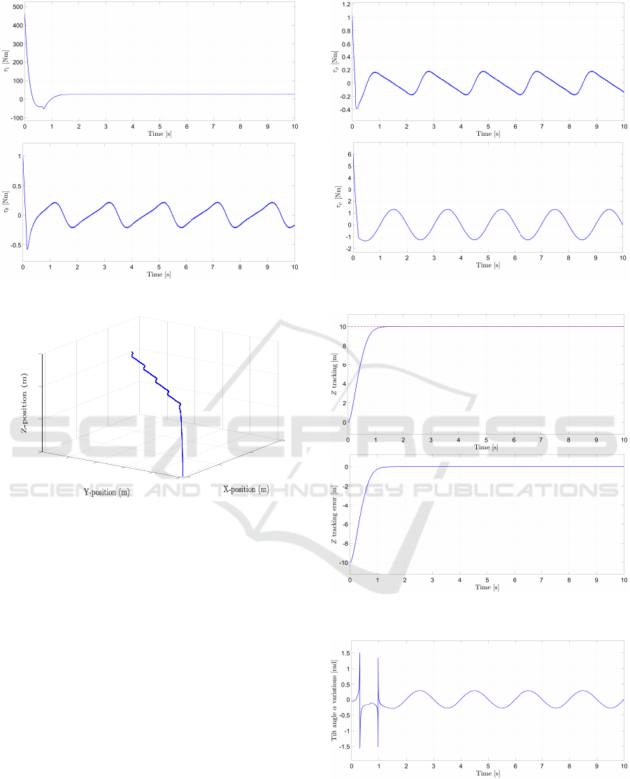
Figure 6: Simulation results of control inputs.
3
0
2
10
5
8
6
10
1
4
15
2
0
0
Figure 3: Simulation results of 3D altitude and attitude
tracking.
attitude positions to their known desired position tra-
jectories with high precision due to the good rejection
of uncertainties and disturbances as shown in Figs. 4
and 7. This is confirmed by the small values of the al-
titude and attitude tracking error as depicted in Figs. 4
and 8. Moreover, the range of variation of the tilt an-
gle α of the third rotor placed in the backward part in
Fig. 5 is fitting the mechanical structure of the system.
Figure 6 shows that the control torque inputs effort is
very small and chattering free. The values of the con-
trol torque inputs are acceptable for our tri-rotor UAV
system.
5 CONCLUSIONS
In this paper, a robust modified second order sliding
mode control has been designed and successfully si-
mulated on a tri-rotor UAV system for the problem of
altitude and attitude tracking in presence of uncertain-
Figure 4: Simulation results of finite-time altitude tracking
and tracking error.
Figure 5: Simulation results of tilt angle variations.
ties and disturbances. The proposed controller ensure
robustness by rejecting the effects of the uncertainties
and allowing chattering elimination. The obtained si-
mulation results on the considered tri-rotor UAV sy-
ICINCO 2018 - 15th International Conference on Informatics in Control, Automation and Robotics
440
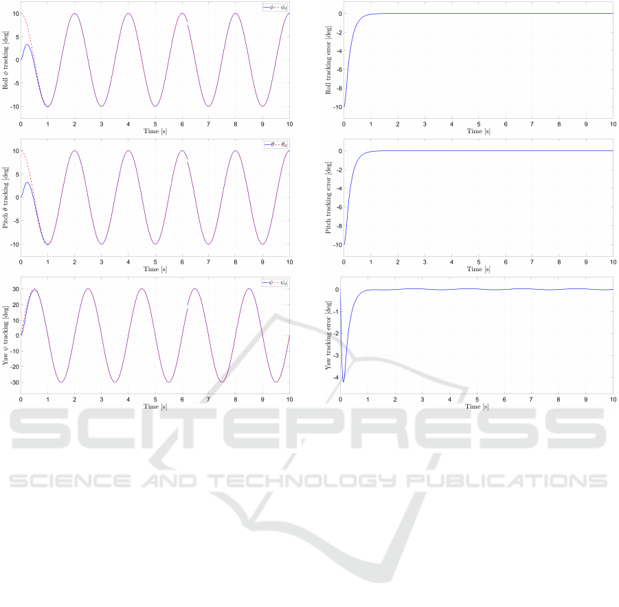
Figure 7: Simulation results of finite-time attitude tracking.
stem show clearly the effectiveness of the proposed
modified super-twisting control algorithm in the alti-
tude and attitude tracking and disturbance rejection.
ACKNOWLEDGEMENTS
This work was supported by the Paraguayan Science
and Technology National Council - CONACYT
(PINV15-0136).
REFERENCES
Ahmed, B., Pota, H. R., and Garratt, M. (2006). Flight
control of a rotary wing UAV using backstepping. In-
ternational Journal of Robust and Nonlinear Control,
20(6):639–658.
Benallegue, A., Mokhtari, A., and Fridman, L. (2008). Hig-
horder slidingmode observer for a quadrotor UAV. In-
ternational Journal of Robust and Nonlinear Control,
18(45):427–440.
Besnard, L., Shtessel, Y. B., and Landrum, B. (2012). Qua-
drotor vehicle control via sliding mode controller dri-
ven by sliding mode disturbance observer. Journal of
the Franklin Institute, 349(2):658 – 684.
Figure 8: Simulation results of attitude tracking error.
Boiko, I. and Fridman, L. (2005). Analysis of chattering in
continuous sliding-mode controllers. IEEE Transacti-
ons on Automatic Control, 50:1442–1446.
Ceccarelli, N., Enright, J. J., Frazzoli, E., Rasmussen, S. J.,
and Schumacher, C. J. (2007). Micro UAV path plan-
ning for reconnaissance in wind. In ACC, American
Control Conference, pages 5310–5315.
Davila, J. and Salazar, S. (2017). Robust control of an un-
certain UAV via high-order sliding mode compensa-
tion. IFAC-PapersOnLine, 50(1):11553 – 11558.
Derafa, L., Benallegue, A., and Fridman, L. (2012). Super
twisting control algorithm for the attitude tracking of
a four rotors UAV. Journal of the Franklin Institute,
349(2):685 – 699.
Fridman, L. (2001). An averaging approach to chattering.
IEEE Transactions on Automatic Control, 46:1260–
1265.
Gonz
´
alez-Hern
´
andez, I., Palacios, F. M., Cruz, S. S., Que-
sada, E. S. E., and Leal, R. L. (2017a). Real-time alti-
tude control for a quadrotor helicopter using a super-
twisting controller based on high-order sliding mode
observer. International Journal of Advanced Robotic
Systems, 14(1):1–15.
Gonz
´
alez-Hern
´
andez, I., Salazar, S., Munoz, F., and Lo-
zano, R. (2017b). Super-twisting control scheme
for a miniature quadrotor aircraft: Application to
trajectory-tracking problem. In ICUAS, Internatio-
nal Conference on Unmanned Aircraft Systems, pages
1547–1554.
Finite-Time Altitude and Attitude Tracking of a Tri-Rotor UAV using Modified Super-Twisting Second Order Sliding Mode
441

Guzm
´
an, E. and Moreno, J. A. (2015). Super-twisting
observer for second-order systems with time-varying
coefficient. IET Control Theory Appl., 9(4):553–562.
Ibarra, E. and Castillo, P. (2017). Nonlinear super twisting
algorithm for UAV attitude stabilization. In ICUAS,
International Conference on Unmanned Aircraft Sys-
tems, pages 640–645.
Kali, Y., Rodas, J., Gregor, R., Saad, M., and Benjelloun,
K. (2018a). Attitude tracking of a tri-rotor UAV based
on robust sliding mode with time delay estimation. In
ICUAS, International Conference on Unmanned Air-
craft Systems.
Kali, Y., Rodas, J., Saad, M., Gregor, R., Benjelloun, K.,
and Doval-Gandoy, J. (2017a). Current control ba-
sed on super-twisting algorithm with time delay es-
timation for a five-phase induction motor drive. In
IEMDC, IEEE International Electric Machines and
Drives Conference, pages 1–8.
Kali, Y., Saad, M., and Benjelloun, K. (2017b). Non-
singular terminal second order sliding mode with time
delay estimation for uncertain robot manipulators. In
ICINCO, International Conference on Informatics in
Control, Automation and Robotics, pages 226–232.
Kali, Y., Saad, M., Benjelloun, K., and Benbrahim, M.
(2015). Sliding mode with time delay control for
mimo nonlinear systems with unknown dynamics. In
2015 International Workshop on Recent Advances in
Sliding Modes (RASM), pages 1–6.
Kali, Y., Saad, M., Benjelloun, K., and Fatemi, A. (2017c).
Discrete-time second order sliding mode with time de-
lay control for uncertain robot manipulators. Robotics
and Autonomous Systems, 94:53 – 60.
Kali, Y., Saad, M., Benjelloun, K., and Khairallah, C.
(2018b). Super-twisting algorithm with time delay es-
timation for uncertain robot manipulators. Nonlinear
Dynamics.
Lee, D., Ha, C., and Zuo, Z. (2013). Backstepping control
of quadrotor-type UAVs and its application to teleo-
peration over the internet. In Lee, S., Cho, H., Yoon,
K.-J., and Lee, J., editors, Intelligent Autonomous Sys-
tems 12, pages 217–225, Berlin, Heidelberg. Springer
Berlin Heidelberg.
Lee, D., Jin Kim, H., and Sastry, S. (2009). Feedback line-
arization vs. adaptive sliding mode control for a qua-
drotor helicopter. International Journal of Control,
Automation and Systems, 7(3):419–428.
Levant, A. (2003). Higher-order sliding modes, differentia-
tion and output-feedback control. International Jour-
nal of Control, 76(9-10):924–941.
Moreno, J. A. (2014). On strict Lyapunov functions for
some non-homogeneous super-twisting algorithms.
Journal of the Franklin Institute, 351(4):1902 – 1919.
Munoz, F., Bonilla, M., Espinoza, E. S., Gonz
´
alez, I., Sa-
lazar, S., and Lozano, R. (2017a). Robust trajectory
tracking for unmanned aircraft systems using high or-
der sliding mode controllers-observers. In ICUAS,
International Conference on Unmanned Aircraft Sy-
stems, pages 346–352.
Munoz, F., Gonz
´
alez-Hern
´
andez, I., Salazar, S., Espinoza,
E. S., and Lozano, R. (2017b). Second order sliding
mode controllers for altitude control of a quadrotor
uas: Real-time implementation in outdoor environ-
ments. Neurocomputing, 233:61 – 71.
Nex, F. and Remondino, F. (2014). UAV for 3d mapping
applications: a review. Applied Geomatics, 6(1):1–15.
Pflimlin, J. M., Soueres, P., and Hamel, T. (2004). Hovering
flight stabilization in wind gusts for ducted fan UAV.
In CDC, IEEE Conference on Decision and Control,
volume 4, pages 3491–3496.
Runcharoon, K. and Srichatrapimuk, V. (2013). Sliding
mode control of quadrotor. In TAEECE, Internatio-
nal Conference on Technological Advances in Elec-
trical, Electronics and Computer Engineering, pages
552–557.
Sankaran, S., Khot, L. R., Espinoza, C. Z., Jarolmasjed, S.,
Sathuvalli, V. R., Vandemark, G. J., Miklas, P. N., Car-
ter, A. H., Pumphrey, M. O., Knowles, N. R., and Pa-
vek, M. J. (2015). Low-altitude, high-resolution aerial
imaging systems for row and field crop phenotyping:
A review. European Journal of Agronomy, 70:112 –
123.
Segales, A., Gregor, R., Rodas, J., Gregor, D., and Toledo,
S. (2016). Implementation of a low cost UAV for pho-
togrammetry measurement applications. In ICUAS,
International Conference on Unmanned Aircraft Sys-
tems, pages 926–932.
Singh, K. K. and Frazier, A. E. (2018). A meta-analysis and
review of unmanned aircraft system (UAS) imagery
for terrestrial applications. International Journal of
Remote Sensing, 0(0):1–21.
Tseng, M. and Chen, M. (2010). Chattering reduction of
sliding mode control by lowpass filtering the control
signal. Asian Journal of Control, 12(3):392–398.
Utkin, V., Guldner, J., and Shi, J. (1999). Sliding mode
control in electromechanical systems. Taylor-Francis.
Voos, H. (2009). Nonlinear control of a quadrotor micro-
UAV using feedback-linearization. In ICMA, Interna-
tional Conference on Mechatronics, pages 1–6.
Yang, S. and Xian, B. (2017). Trajectory tracking cont-
rol design for the system of a quadrotor UAV with a
suspended payload. In CCC, Chinese Control Confe-
rence, pages 777–782.
Zheng, E.-H., Xiong, J.-J., and Luo, J.-L. (2014). Second
order sliding mode control for a quadrotor UAV. ISA
Transactions, 53(4):1350 – 1356.
Zhou, Q. L., Zhang, Y., Rabbath, C. A., and Theilliol, D.
(2010). Design of feedback linearization control and
reconfigurable control allocation with application to a
quadrotor UAV. In SysTol, Conference on Control and
Fault-Tolerant Systems, pages 371–376.
ICINCO 2018 - 15th International Conference on Informatics in Control, Automation and Robotics
442
