
Design and Characterization of a Plug-in Device for Tactile Sensing
Go Otsuka, Masato Niwa, Toshio Kawanishi and Goro Obinata
Department of Robotic Science and Technology, Chubu University, Kasugi 487-8501, Japan
Keywords: Tactile Sensor, Vision-based, Plug-in System, Mechanical Quantity, Adhesiveness.
Abstract: Although the most of the functions of the human upper body can be performed by robotic technologies which
are already developed, the hand and finger functions cannot be achieved by artificial alternatives, particularly
concerning the dexterous manipulation. One of the reasons is the lack of tactile sensors like the ones observed
in the human fingertip. The purpose of this paper is to design a vision-based tactile sensor with the size of a
fingertip, and valuated it under several conditions of contact. The resolution performance of the developed
vision-based sensor for measuring contact force and contact moment is shown based on preliminary
experiments. Moreover, the results of these experiments show the potential of the proposed sensor for
evaluating adhesive surfaces.
1 INTRODUCTION
In industry, there is a demand to replace the work of
human resources by autonomous systems. Although
the most of the functions of the human upper body
can be performed by already developed robotic
technologies, the hand and finger functions
functionalities cannot be achieved by artificial
alternatives, particularly concerning the dextrous
manipulation. One of the reasons is the lack of tactile
sensors like the ones observed in the human fingertip.
Different types of tactile sensors have been proposed
for several purposes (Shinoda, 2002; Lee and
Nicholls, 1999; Maeno, et al., 1998). However, there
are a few artificial fingertip sensors with the
sensibility high as the human`s fingertips. It is
challenging for artificial finger tips to obtain multi
model tactile sensation with small volume and soft
surface of contact. This happens because the
difficulty on installing several single-purpose sensors
in a fingertip-sized chassis, or from the mechanical
requirements of covering the surface of sensor with
soft material. In order to solve this problem, the
MEMS-based sensors can be made compact in size
(Wen and Fang, 2008), but the sensitivity decreases
when the surface is covered with elastic material. The
problem has been improved for obtaining high
sensitivity in temporal and space resolution by several
ideas (Jamone et al., 2015; Shin et al., 2018).
However, there is still the problem of the multi-modal
haptic sensing with single sensor.
Vision-based sensors with soft surface were
proposed to achieve tactile sensation like the ones
observed in human fingertips (Obinata, et al., 2007;
Ito, et al., 2011a; Ito, et al., 2011b; Ito, et al., 2012;
Ito, et al., 2014). Its design consists of a digital camera,
LED light and a soft-pad for touching. The
measurement is based on deformations of the pad
surface, which reflects the contact surface. A very
small camera captures the alterations in the pad
surface, and an algorithm is able to analyze the
changes in the images in order to measure the contact
surface. The sensor is able to measure dynamic
characteristics: multi-dimensional force and moment,
degree of adhesion and shape of the contact surface.
The important feature worth noting is that the sensor
is able to estimate the adhesion degree with the
contact surface, then determine whether the contact
object moves (macro slipping) or stays with the
sensor surface (incipient slip) under a certain
amplitude of pressure force. This means that the
sensor is able to provide information in order to
prevent from macro slipping based on the estimating
degree of adhesion with the contact surface (Ito, et al.,
2011a). This type of sensor has been designed to the
medical use of palpation for pathological soft tissues
because the sensor could be integrated with the
endoscope (Yeh et al., 2010).
Although vision-based sensors have various
advantages, such as the ability of estimating adhesion
degree, these sensors still did not reached the high
implementability performance. One of the main
488
Otsuka, G., Niwa, M., Kawanishi, T. and Obinata, G.
Design and Characterization of a Plug-in Device for Tactile Sensing.
DOI: 10.5220/0006890304880493
In Proceedings of the 15th International Conference on Informatics in Control, Automation and Robotics (ICINCO 2018) - Volume 1, pages 488-493
ISBN: 978-989-758-321-6
Copyright © 2018 by SCITEPRESS – Science and Technology Publications, Lda. All rights reserved
reason is the usage of analog cameras and the signal
converters used, which require dedicated hardware
and software resources (Ito, et al., 2014). This
situation has changed nowadays due to the usage of
digital cameras and its accessible firmware. Also, the
size and cost reduction of digital cameras, has
potentially raised the application which uses digital
cameras on robotic applications.
The purpose of this paper is to design a vision-
based tactile sensor with the size of fingertip using
small digital cameras which have been recently
available with low cost, and to characterize it under
several conditions of contact. This paper is described
as follows: The structure and the components are
illustrated in chapter 2. Chapter 3 describes the
developed software to read the obtained image. The
preliminary results of the experiments, which shows
the resolution of the sensor for measuring contact
force and contact moment, are given in chapter 4.
Then in chapter 5, it is described experiments with
compliant objects having adhesive surfaces. Finally,
the chapter 6 show the conclusion and future works
2 STRUCTURE OF SENSOR
The designed vision based tactile sensor consists of a
CMOS camera, a touch pad, a half mirror and a
surface-emitted LED. The components are shown
with the placements in Figure.1. The values are L =
12mm, B = 7mm, W = 27mm, H = 20mm, and D =
19mm. The CMOS camera works with preinstalled
lens. The angular field of view of the lens is 53
degrees, and the focal length is 19mm. The size of
the sensor is defined according to these values. The
pad is transparent and soft, and it is installed to the
casing with a transparent rigid liner.
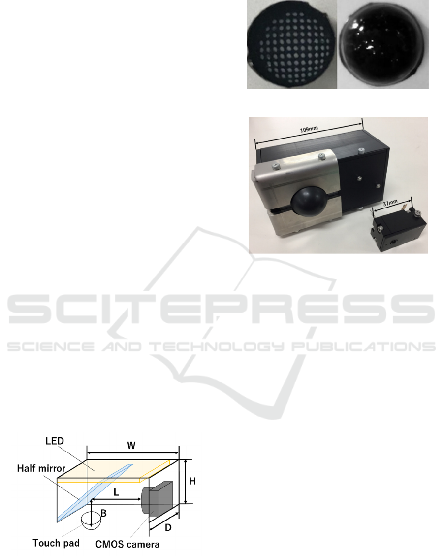
Figure 1: Structure and dimensions of the sensor.
Figure 2: Touch pad.
Figure 3: Examples of different sizes for the developed
sensor.
The rigid liner is set to prevent the pad from being
moved inward the sensor structure. The CMOS
camera captures the inside image of the touch pad
through the half mirror. A picture of the touch pad is
shown in Figure 2. A black rubber membrane covers
the pad surface. White dots are printed into a lattice
pattern inside of the membrane, with pitches of
0.1mmin, on both directions. Through the dots
position, it is possible to calculate the deformation of
the pad. The details about the method of analyzing the
deformation of the touch pad to estimate the targets
are described in the following chapters. The structure
of the entire sensor has only 4 components, allowing
large freedom in scalability of sensor design as show
in Figure 3, where the sensor can have different sizes.
3 SPECIFICATION AND
SOFTWARE
In this chapter it is described the details regarding the
software used to analyze the image from the touch
pad, and specification regarding the implementation
of the components present in the sensor structure.
Table 1 and Table 2 show the specification of COMS
camera and the USB interface to PC.
Design and Characterization of a Plug-in Device for Tactile Sensing
489
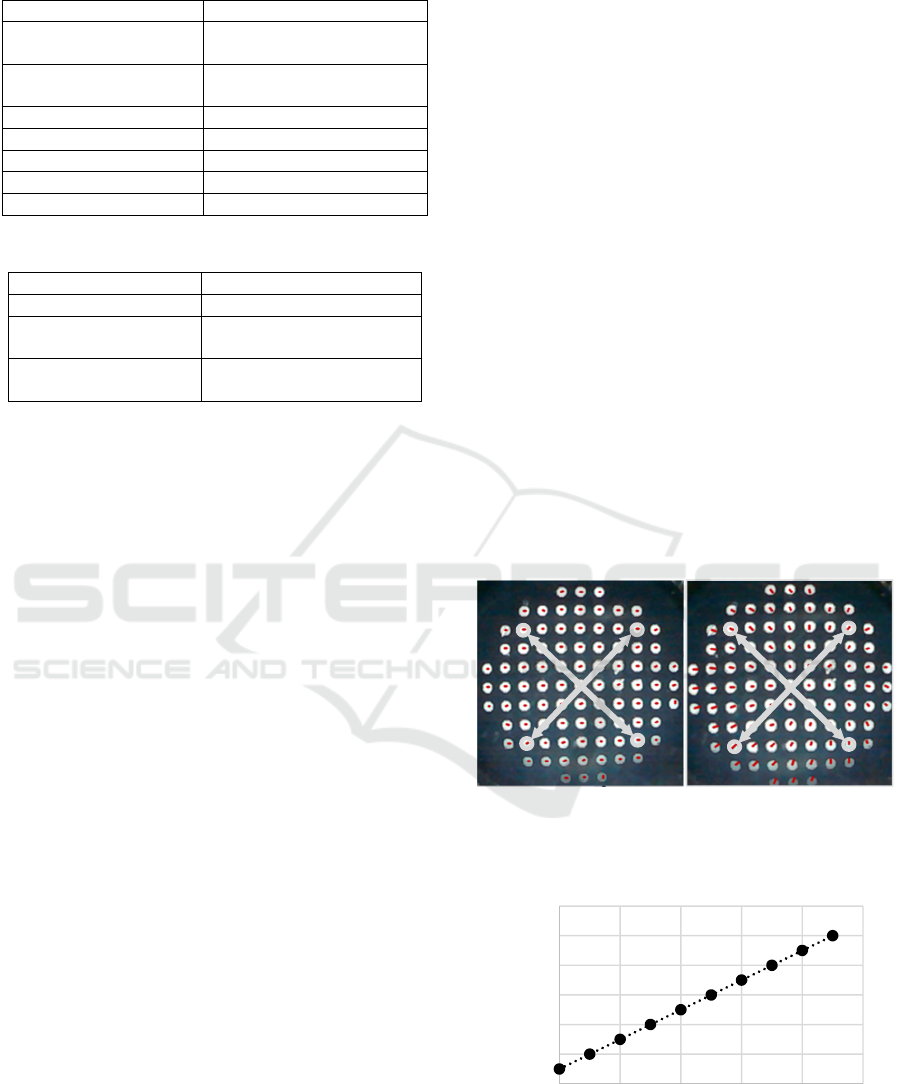
Table 1: CMOS camera (Asahi Electro. Lab., PPV404C).
External dimensions 8.0mm×8.0mm×5.5mm
Image pickup device 1/4 inch CMOS Color
image sensor
Digital output
compatible
YUV422/RGB565
8bit Parallel output
Pixel size 5.55μm×5.55μm
Angle of view 51°
Focal length 19mm
Number of pixels 640(H) ×480(V)
Frame cycle MAX30fps
Table 2: USB interface (AEL-USB-A).
External dimensions 20mm×45mm×7.3mm
Input voltage USB bus power
External connection
method
USB-mini B
Operation guarantee
temperature
0~70
The USB interface makes it possible for the sensor
to transmit the captured images to a desktop computer.
There is no particular requirement for that
communication, since the USB interface in the
operational system handle the process. It was
developed a program which translates the
deformation of the pad to desired contact information.
The program (written in C++) includes openCV
functions for the image processing.
Depending on the application, it should be
selected the appropriate configuration for the digital
camera, which relies on two main aspects: the
communication frame rate and the camera resolution.
The image acquisition frame rate of the touch pad is
highly related to the required sampling rate of the
control loop, if the sensor is applied for robot gripper
control. If the control loop requires a reference
parameter with a higher rate, then the communication
speed need to be higher as possible.
Nowadays digital cameras are available with high
communication speed. However, higher resolution of
measuring physical quantity, like multi-dimensional
force, requires the higher space resolution of the
camera. Such higher resolution means much image
information, and results in more computational time.
This means that there is a trade-off between the
measuring resolution and the speed of processing.
4 EXPERIMENTAL RESULTS OF
FORCE MEASUREMENT
In order to show the potential of the designed sensor,
experiments of force sensing were carried out. It was
assumed that the contact object for the sensor has flat
surface. The idea for measuring the force and
moment at the sensor pad is to observe the relation
between the amount of characteristics in the captured
image from the pad and the physical quantities, such
as force and moment.
4.1 Normal Force
When a normal force is applied to the sensor pad with
a flat surface, the dots on the captured image move
radially from the center to the outside of the pad. This
movement is quantified according to the default
distance between the dots in the touch pad to the
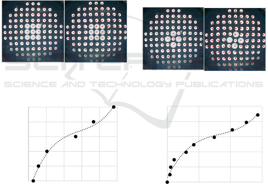
distance presenting in the image. The distance
between two dots located at each opposing corner, as
show in Figure 4, is taken for the quantification.
The two distances are measured, and its average
value is calculated. In Figure 5, the average values
are compared with the applied normal forces, which
are measured by a calibrated equipment (3
dimensional force sensor: USL06-H5200N-C, Tec
Gihan). There is a linear direct relationship between
the applied normal force and the distance on the
captured image. This makes it possible to estimate the
normal force from the image of the pad.
(a) (b)
Figure 4: Definition of the distances. (a) Image in non-
contact state. (b) Image under a normal force.
Figure 5: The normal force and the average of the two
normalized distances.
0
2
4
6
8
10
12
1 1,2 1,4 1,6 1,8 2
Nomal Force[N]
Normalized distance
ICINCO 2018 - 15th International Conference on Informatics in Control, Automation and Robotics
490
4.2 Tangential Force
The dots on the captured image move to the opposite
direction when a tangential force is applied to the
sensor pad flat surface. This movement is quantified
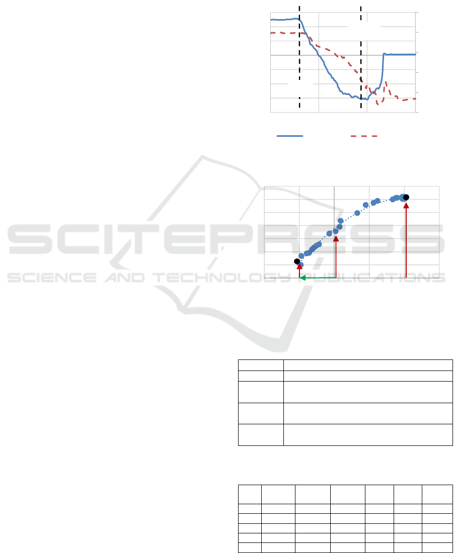
according to the dots displacements on the image. We
take the displacements of nine dots around the center
of the touch pad (see the red circles in Figure 6). It is
measured the displacements of these dots, and the
average value is calculated. In Figure 7, the average
values are compared with the applied tangential
forces, which are measured by the same equipment as
normal force calibration. The relationship between
the tangential force applied to the dots deformation is
show in the Figure 7. From this information it is
possible to estimate the tangential force applied to the
touch pad surface.
(a) (b)
Figure 6: Definition of the nine dots and the displacements.
(a) Image in non-contact state. (b) Image under a tangential
force.
Figure 7: The relation between the tangential force and the
average value of the nine dots displacements.
4.3 Moment
When a certain amount of rotational moment is
applied to the sensor pad flat surface, some dots
around the center on the captured image do a
rotational movement in the opposite rotational
direction to the moment applied. The rotation is
quantified following the same procedure used for the
tangential and normal forces. The calculation focus
on the four dots around the center dot, and it is
calculated the rotation angle based on the touch pad
when no rotational force is applied (see the red circles
in Figure 8). It is measured the rotation angles from
the four dots locations. In Figure 9, the values are
compared with the applied moments, which are
measured by a calibrated device for moment value.
The estimation of the moment is calculated in the
same way as the tangential and normal force.
(a) (b)
Figure 8: Definition of distances. (a) Image in non-contact
state. (b) Image under a moment.
Figure 9: The relation between moment and the rotation
angle.
0,2
0,3
0,4
0,5
0,6
0,7
12,545,578,5
Tangential force[N]
Displacement in pixels
0
5
10
15
20
25
0123
Moment[N・mm]
Average angle of dots [deg]
Design and Characterization of a Plug-in Device for Tactile Sensing
491
5 SENSING WITH ADHESIVE
SURFACE
One of the feature present in the developed sensor is
the ability to measure contact area of interaction. It is
possible to apply the sensor observation to analyze
the slide processes from adhesive objects.
This indicates the possibility for evaluating
adherence property. To confirm this possibility, series
of experiments were conducted where the sensor
touched an adhesive surface with a certain amount of
pressure and peeled off.
It is measured the change in the different types of
forces during the sliding process. Figure 10 shows an
example of the time response in the normal force
acting between the sensor pad and the object surface.
The temporal sequence of the contact area is also
shown in the figure. First, the initial force with
predefined amplitude was applied to the object
surface with the touch pad of sensor, and then started
a process to lower the force from time T1. The force
reached the minimum at time T2. It is noted that the
pressure at T2 took negative value and it relaxed
afterwards. The final value of the contact area did not
become zero, even if the force became zero. This
happens because the estimation algorithm of the
sensor for measuring the contact area has a certain
error. The algorithm is based on distinguishing the
border of the contact area and the non-contact area on
the captured image. Improvement on this approach
will be required to obtain better estimates.
Two different objects were selected to measure
the force and the contact area during experiments of
attaching/peeling-off. Those objects are different
both in the elastic compliance and in the adhesiveness.
The behaviour of the peeling-off process can be
illustrated in force-area space; one example of force-
area plot is given in Figure 11. The peeling-off
process starts at Pb and the point indicated by the pair
of forces and contact area moves towards the left
lower region along the dotted line and reaches Pe. To
characterize the adherence property, five parameters
are defined in the force-area space, and the notations
are given in Table 3. The other parameters defined
below are normalized ones for evaluation over
different materials of touching objects.
The So/Sb is the normalized residual area, and
Se/Sb is the normalized area at the maximum
tensional force. The -Fp/Fi is the normalized force
amplitude which is required for starting peeling-off.
The experimental results with two objects are
shown in Table 4 and Table 5. Table 4 summarizes
the result for the surface of absorption in gel
(polyurethane, Cram Works), which is a material used
to isolate vibrations waves.
The force for peeling -Fp increased according to
the initial applied force Fi. The normalized values –
Fp/Fi took a certain value bigger than 1 and decreased
to 1 as the initial force increased. The residual area is
Figure 10: The time responses in force and contact area.
Figure 11: Force-area space of sliding.
Table 3: Notations on sliding process.
Fi[N] Initial applied force
Sb[mm
2
] Initial contact area
So[mm
2
] Contact area when the applied force becomes
zero (Residual area)
Se[mm
2
] Contact area at the maximum tension with the
adhesive surface and the sensor surface
Fp[N] Force for tearing-off (Adhesive strength just
before tearing off).
Table 4: Parameters for adhesiveness (surface:adsorbing
gel, body:polyurethane).
Fi
[N]
Sb
[mm
2
]
So
[mm
2
]
Se
[mm
2
]
Fp
[N]
So
/Sb
-Fp
/Fi
1 240 200 80 -3.7 0.83 3.7
2 240 215 90 -4.6 0.9 2.3
3 350 275 100 -4.3 0.79 1.43
4 380 320 100 -4.3 0.84 1.075
5 400 350 130 -5.5 0.88 1.1
0
100
200
300
400
500
-8
-6
-4
-2
0
2
4
6
0 5 10 15
Area[mm
2
]
Force[N]
Time[s]
Force[N] Area[mm²]
0
50
100
150
200
250
300
350
-2 -1 0 1 2 3
Area[mm
2
]
Force[N]
Se
So
S
b
Fp
Pb
Pe
T2
T1
ICINCO 2018 - 15th International Conference on Informatics in Control, Automation and Robotics
492

Table 5: Parameters for adhesiveness. (surface:
polyethylene and inorganic mineral filler, body:synthetic
rubber).
Fi
[N]
Sb
[mm
2
]
So
[mm
2
]
Se
[mm
2
]
Fp
[N]
So/
Sb
-Fp
/Fi
1 190 155 150 -0.25 0.82 0.25
2 300 175 100 -0.4 0.58 0.2
3 430 220 100 -0.4 0.51 0.133
4 400 220 100 -0.4 0.55 0.1
5 450 225 100 -0.45 0.5 0.09
then increased according to the initial applied force
Fi; However, the normalized values So/Sb showed
approximately constant values without depending on
the initial force Fi. The normalized residual area
So/Sb showed the values over 0.8 and there was no
large variation. From the results, it is observed a
certain amplitude of force is required to peel off;
however, larger forces are required to peel off when
larger initial forces are applied. It is also observed that
there is a contact area which is independent on the
initial force.
The results of another adhesive object:
polyethylene and inorganic mineral filler (synthetic
rubber, Kokuyo) are summarized in Table 5. The
force for peeling-off –Fp kept constant except for the
case of weakest initial force. The normalized residual
area showed small values in comparison with the
former surface. The normalized residual area So/Sb
decreased when the initial force increased, and the
values are smaller in comparison with the former
object. The tendencies of the parameters in those two
adhesive surfaces are different; therefore, the
parameters may characterize the adhesiveness.
These experimental results suggest the possibility
for evaluating adhesive surfaces. There exist
problems for generalizing the parameters; for an
example, the parameter values are dependent on the
radius of the touch pad of the sensor. Moreover, the
results may depend on the stiffness properties of the
sensor pad and the object on contact.
6 CONCLUSIONS
This paper shows the design of a vision-based tactile
sensor with the size of fingertip. All the components
found in the mechanical design are accessible for the
present market. The main component is a digital
camera, and the data communication interface can be
found in most of PC operational system. The software
is designed to be used widely by other modules (by a
control module for example). The preliminary
experimental results show the resolution performance
of the sensor for measuring contact force and contact
moment. The paper also describes the experiments
with compliant objects having adhesive surfaces.
From these experiments, parameters for evaluating
adhesive surfaces have been proposed. The results on
the parameters show the potential of this sensor for
evaluating adhesiveness.
The design variation will be required for the
specific applications of the medical devices, haptic
feedback systems, human interfaces, and so on. The
less number of components of this sensor will make
it easy to develop for such applications. More
precious arrangement and estimation method for
measuring contact area are expected to adhesive
evaluation with this type of sensor.
ACKNOWLEDGEMENTS
The authors would like to thank BYNAS Co., Ltd,
OOTAHIRO Co., Ltd, ITOBIGEISHA-SEIHAN-
SHO Co., Ltd for their helps in production of the
sensor.
The authors would like to thank Nicholas de
Bastos Melo for his kindly improving English
expressions in the manuscript.
REFERENCES
Ito, Y., Kim, Y., and Obinata, G. (2011a). IEEE Sensors
Journal, 11(9):2037-2047.
Ito, Y., Kim, Y., Nagai, C., and Obinata, G. (2011b). Int. J.
Adv. Robot. Syst, 8(4):25-234.
Ito, Y., Kim, Y., Nagai, C., and Obinata, G. (2012). IEEE
Trans. Autom. Sci. Eng, 9(4):734-744.
Ito, Y., Kim, Y., and Obinata, G. (2014). Adv. Robot. Autom,
3(1):1-9.
Jamone L., Natale L., Metta, G., Sandini G. (2015). IEEE
Sensors Journal, 15(8):4226-4233.
Lee, M. H. and Nicholls, H. R. (1999). Mechatronics, 9:1-31.
Maeno, T., Kobayashi, K., Kawai, T., and Hirano, Y. (1998).
Japanese Society of Mechanical Engineers, 64(620):
1258-1265.
Obinata, G., Ashish, D., Watanabe, N., and Moriyama, N.
(2007). Mobile Robots: Perception & Navigation, pro
literature Verlag, Mammendorf, Germany: 137-148.
Shin, K., Sim, M., Park, H., Cho, Y., Sohn, J. I., Cha, S. N.,
Jang, J. E. (2018). Proceedings of Haptic Symposium,
San Francisco: 95-99.
Shinoda, H. (2002). Japanese Robotic Society, 20(4):385-
388.
Wen, C. and Fang, W. (2008). Sensors and Actuators A:
Physical, 145–146:14–22.
Yeh, C. S., Ju, M. S., Martynenko, Y., Goryacheva, I. Su, F.
C. (2010), 6
th
World Congress of Biomechanics,
Singapore, IFMBE Proceedings, 31:1270-1273.
Design and Characterization of a Plug-in Device for Tactile Sensing
493
