
Dynamic Estimation of Visco-elastic Mechanical Characteristics of
Biological Samples under Micro Manipulation
Paolo Di Giamberardino
1
, Maria Laura Aceto
1
, Oliviero Giannini
2
and Matteo Verotti
2
1
Dept. Computer, Control and Management Engineering Antonio Ruberti, Sapienza University of Rome, Italy
2
University Niccol Cusano, Via Don Carlo Gnocchi 3, Rome, Italy
Keywords:
Micro Manipulation, Nano Scale Devices, Biological Samples Analysis, Visco-elastic Characteristic Measu-
rement, Dynamic Parameters Estimation.
Abstract:
This paper focuses on the possibility of using a recently fabricated micro gripper for the on line estimation
of the mechanical characteristics (damping and elasticity) of a sample pinched by the jaws, with particular
reference to biological tissues. A classical on line dynamical parameter estimator is computed for the given
system with different estimation computations, and its effectiveness has been verified by numerical simulati-
ons. Results confirm the feasibility of a micro-robotic clinical device for surgery use equipped with a tissue
recognition ability.
1 INTRODUCTION
Robotics has gained a continuously increasing impor-
tance in medical fields, especially in surgery and di-
agnostic aspects. Great attention has been given to
robotic assisted surgery, where the robots in use are
of human scale (Fontanelli et al., 2017).
However, there are several cases in which the di-
mensions of the robotic devices are required to be as
small as possible, like in vascular surgery or mini in-
vasive interventions. During these operations, the ca-
pability of detecting and identify the tissues under ex-
amination, or the different characteristics of part of
them, could help the surgeon to perform its task.
One of the most promising technique is based on
the estimation of the mechanical characteristics of the
samples, specifically their visco-elastic properties.
The possibility of detecting the characteristics of
tissues both in surgery and in analysis operations is a
strong opportunity for clinical developments. In fact,
Literature contains a large number of works confir-
ming the importance of measuring the visco-elastic
characteristics of a tissue. Foe example, brain tissues
are addressed in (Morrison III et al., 1998), human
skin in (Edsberg et al., 2000), reconstituted tissues in
(Wakatsuki et al., 2000). In (Guido et al., 2011), the
use of dielectrophoretic forces are used to distinguish
cell types by means of stretching tests.
The dynamic characteristics of tissues play a fun-
damental role in the analysis methods, and the results
of some tests about the dynamic response of the tis-
sues are reported in (Kiss et al., 2004).
The usefulness of the identification of the tissue
elasticity properties during surgical operations is dis-
cussed in (Tavakoli et al., 2006). For example, the
relationships between elastic and viscoelastic proper-
ties of undifferentiated adipose-derived stem cells and
lineage-specific metabolite production are studied in
(Gonz
´
alez-Cruz et al., 2012). To perform these tasks,
additional sensors like vision systems can also be im-
plemented (Boonvisut and C¸ avus¸o
ˇ
glu, 2013).
In order to better investigate the characterization
and the influence of the mechanical response of tis-
sues in physiological or pathological aspects, the de-
velopment of mathematical models plays an impor-
tant role for successful results. A review of this aspect
can be found in (Choi, 2016), whereas mechanical
concepts can be applied to interpret deformation pro-
file of aspirated soft tissues, as in (Nava et al., 2004;
Nava et al., 2008).
All the recalled examples show the importance of
being able to recognise the mechanical characteristics
of a tissue, often at a micro or nano scale. Displace-
ment and force sensors can help for acquiring measu-
rements to be used for system identification.
Parameter estimation problems are not limited to
small scale systems; the often arise in robotic cont-
rol applications. Still referring to medical systems,
for example in (Wilkening and O., 2014), the estima-
tion of mass parameters for a safe and comfortable
Giamberardino, P., Aceto, M., Giannini, O. and Verotti, M.
Dynamic Estimation of Visco-elastic Mechanical Characteristics of Biological Samples under Micro Manipulation.
DOI: 10.5220/0006914405030510
In Proceedings of the 15th International Conference on Informatics in Control, Automation and Robotics (ICINCO 2018) - Volume 2, pages 503-510
ISBN: 978-989-758-321-6
Copyright © 2018 by SCITEPRESS – Science and Technology Publications, Lda. All rights reserved
503

human–robot interaction is considered for robot assis-
ted rehabilitation of patients after surgical interventi-
ons.
In (Cao et al., 2015), a two arms nursing care ro-
bot is studied. The knowledge of mechanical parame-
ter as the contact points between the two arms and a
carried body, or the full system center of gravity du-
ring body manipulation, plays an important role for a
efficient and effective control operations. Then, the
possibility of estimating the center of mass position
in different cases of contact situation is studied.
These examples, among many others, in several
fields of robotic applications are a valid demonstra-
tion of the importance and the interest in the parame-
ter estimation problems.
Several solutions are available for parameter esti-
mation of dynamical systems, depending on the cha-
racteristics of the sensor signals, the linearity or the
non linearity of some relationships, and other structu-
ral properties of the model.
In this work, the possibility of using a microgrip-
per for the evaluation of the mechanical characteris-
tics of biological samples is presented, considering an
estimation algorithm for the viscosity and elastic pa-
rameters under generic control torques. The paper is
organised as follows. The microdevice is introduced
in Section 2, whereas the mathematical model is dis-
cussed in Section 3. The adopted identification algo-
rithms are described in Section 4, and some numerical
results are reported and discussed in Section 5.
2 THE EXPERIMENTAL DEVICE
The microsystem considered in this paper, depicted
in Figure 1, is described in detail in (Bagolini et al.,
2017) and (Di Giamberardino et al., 2018). The de-
vice is fabricated as a silicon monolithic structure,
arranged with a comb drive at the anchor of each
jaw. The comb actuators exert the input torques that,
through the deflections of a flexure hinge (Verotti
et al., 2015; Verotti et al., 2017), move the jaws during
the gripping tasks (Cecchi et al., 2015). As reported in
(Bagolini et al., 2017), the fabrication method adop-
ted makes use of Deep Reactive-Ion Etching applied
on Silicon on Insulator wafer.
The operative situation is drawn in Figure 1, in
which the sample is pinched by the gripper and is kept
between the jaws. The points A and D represent the
hinges/actuators, while the points B and C are the con-
tact points between the jaws and the sample.
The operational problem has been already inves-
tigated in (Bagolini et al., 2018) and (Di Giamberar-
dino et al., 2018), where an estimation of the elas-
Figure 1: The gripping system in a generic configuration.
tic and viscous coefficients of the mechanical mo-
del of the sample was provided during simulations
with input signals of suitable waveform. In particular,
in (Bagolini et al., 2018), the elastic coefficient was
obtained gripping the sample by actuating the comb
drive connected to the first jaw, until the second comb
drive reached a predefined angular displacement (suf-
ficiently small to guarantee the safeness of the sam-
ple). This particular actuation choice arises from the
fact that the device is not equipped with a force or
torque sensor. The hypothesis of gripper joints cha-
racterized by a lower elastic coefficient than the one
of the sample should assure that, for small joint angle
displacements, the gripping force would not be dan-
gerously high.
This critical action is provided by means of a feed-
back control scheme in which the safe displacement
of the second joint is the reference signal. The elastic
coefficient is then computed, at steady state conditi-
ons, from the measurement of the jaws angular dis-
placements.
The measurement scheme was improved in
(Di Giamberardino et al., 2018), in order to estimate
also the viscosity coefficient. At the basis of the com-
putation there is the almost linearity conditions un-
der small and slow state variables evolution. Then, a
sinusoidal input of sufficiently small amplitude was
added to the first joint. The viscous coefficient was
obtained by making use of the linearised dynamics or
of the nonlinear characteristics of the viscosity as a
function of the frequency of the input torque.
In this paper, the possibility of using an estimation
algorithm for the viscosity and elastic parameters of
the crimped sample under generic control torques is
presented.
The algorithm is based on the particular structure
of the mathematical model: despite its general non
linearity, it results linear with respect to the unknown
parameters. Section 3 is devoted to a brief recall of
the mathematical model which is used in Section 4 to
design the estimator system.
ICINCO 2018 - 15th International Conference on Informatics in Control, Automation and Robotics
504

3 THE MATHEMATICAL MODEL
The mathematical model refers to the case of full con-
tact condition between the jaws and the sample at
points B and C of Figure 1, i.e. during the measu-
rement phase. Then, the quadrilateral ABCD consti-
tute a closed chain composed by the links AD (the
base), AB and CD (the jaws), and BC (the sample).
All the links have a fixed length with the exception
of the sample dimension BC, whose compression is
at the basis of the measurement. The different mate-
rials constituting the device and the sample is at the
basis of the assumption that the stiffness of the jaws
is much greater than the one of the sample.
For sake of simplicity in the model representation,
all the considered variables are referred to an initial
condition in which the gripper, in a symmetrical con-
figuration, is in touch without deformation of the sam-
ple.
Then, following the notation introduced in (Di Gi-
amberardino et al., 2018) and with reference to Figure
1, the orientation of the two jaws are denoted by
˜
θ
i
,
and the reference values by
ˆ
θ
i
. Therefore, the angles
θ
i
=
˜
θ
i
−
ˆ
θ
i
represent the relative angular displace-
ments of the two links from their neutral configura-
tion, with i = 2 for the left link and i = 4 for the right
one.
Simple geometric considerations give
ˆ
θ
2
= π−
ˆ
θ
4
.
Considering the two contact points B and C, the
orientation of the line BC has the same notation, with
i = 3 and
ˆ
θ
3
= 0. The angles are defined according
to the counter clockwise rule. The reference value for
the distance BC, corresponding to zero elastic reaction
force of the sample, is denoted by ˆu, and its actual
value by ˜u. Therefore, the deformation is equal to
u = ˜u − ˆu.
The values of the variables in the neutral condition
are given in Table 1.
Table 1: Constants.
Parameter Numerical value
ˆ
θ
2
1.44 rad
ˆ
θ
4
1.70 rad
ˆu 150 · 10
−6
m
The following parameters are defined:
i. l is the common length of the two links which con-
stitutes the jaws, i.e. the distances AB and CD;
ii. d is the distance between the hinges (AD);
iii. k
2
, k
4
and K are the torsional stiffness of the two
jaws and the stiffness coefficient of the tissue sam-
ple, respectively;
iv. c
2
, c
4
and c are the viscous damping coefficients
of the two jaws and of the sample, respectively;
v. I
2
and I
4
are the two jaws moments of inertia
around A and D;
vi. τ
2
and τ
4
are the input torques generated by the
comb drives.
The symmetry of the neutral configuration implies
the relationship ˆu = d −2l cos
ˆ
θ
2
.
The angular dynamical model of each of the two
links can be computed. For the first joint, with
subscript 2, from the torque balance condition and as-
suming the inertia of the sample negligible, one has
I
2
¨
θ
2
= −c
2
˙
θ
2
− k
2
θ
2
− cl sin
˜
θ
2
− θ
3
˙u
−kl sin
˜
θ
2
− θ
3
u + τ
2
, (1)
while for the second one, with subscript 4, the corre-
sponding expression is
I
4
¨
θ
4
= −c
4
˙
θ
4
− k
4
θ
4
+ cl sin
˜
θ
4
− θ
3
˙u
+kl sin
˜
θ
4
− θ
3
u + τ
4
. (2)
For the device here considered, the values of the
parameters appearing in (1) and (2) are reported in
Table 2. These values, together with the ones in Table
1, can help to figure out the whole dimension of the
gripper.
Table 2: Numerical values of the parameters.
Parameter Numerical value
d 5.47 · 10
−4
m
l 1.496 · 10
−3
m
I
2
, I
4
1.25 · 10
−14
kg m
2
k
2
, k
4
0.30 · 10
−6
(Kg m
2
) / (s
2
rad)
c
2
, c
4
1.24 · 10
−12
(Kg m
2
) / (s rad)
The system has two degrees of freedom and then
it is fully described by equations (1) and (2). In fact,
since the closed kinematic chain configuration is con-
sidered, it is possible to compute the remaining vari-
ables θ
3
and u and their time derivatives as functions
of the state variables θ
2
, θ
4
,
˙
θ
2
and
˙
θ
4
.
Such computations are reported in (Di Giamber-
ardino et al., 2018) and follow geometric considerati-
ons on the quadrilateral ABCD. The results are here
reported:
θ
3
= arctan
−l sin
˜
θ
2
+ l sin
˜
θ
4
d − l cos
˜
θ
2
+ l cos
˜
θ
4
, (3)
˜u =
q
d − l cos
˜
θ
2
+ l cos
˜
θ
4
2
+
l sin
˜
θ
4
− l sin
˜
θ
2
2
u = ˜u − ˆu (4)
˙u =
˙
θ
2
l sin
˜
θ
2
− θ
3
−
˙
θ
4
l sin
˜
θ
4
− θ
3
. (5)
An interesting observation is that the computation
of
˙
θ
3
is not required.
Dynamic Estimation of Visco-elastic Mechanical Characteristics of Biological Samples under Micro Manipulation
505

4 MECHANICAL
CHARACTERISTICS
ESTIMATION OF SAMPLES
As discussed in the Introduction, important aspects
when dealing with robotics in surgery are the recog-
nition of the different tissues, as well as the different
characteristics of parts of the same tissue. Robotic
assisted tissue identification and characterization for
a pure diagnostic purpose is another important aspect
that is usually addressed.
As recalled in Section 2, a measurement scheme
has been proposed for the elastic properties (Bagolini
et al., 2018) and then for the viscous characterization
(Di Giamberardino et al., 2018). The necessity of par-
ticular input signal waveforms to perform such mea-
surements is compatible with clinical diagnostic tests
applications, but it is not suitable for a tissue mani-
pulations during surgery operations. This latter case
implies the adoption of a measurement scheme able to
work under any input and operative conditions. The-
refore, an on line dynamical estimator is proposed as
a more efficient strategy for the sample characteriza-
tion.
A simple approach to system parameters identi-
fication makes use of numerical solutions based on
recursive least square methods. The condition under
which this kind of techniques can be successfully ap-
plied is that the set of parameters to be estimated ap-
pear linearly in the dynamics. In fact, in this case,
the model can be rearranged in the form of a linear
time varying systems in which the parameters to be
identified are the unknowns, and all the other terms
are function of the state and of the output variables,
supposed measurable. This technique has been fruit-
fully used in several applications, as for example in
((Flacco et al., 2011; Lundquist and Sch
¨
on, 2009; Va-
hidi et al., 2005; Lee and Jung, 2016)).
The structure in which the dynamics has to be re-
written is
y
i
(t) = M
i
(t)ω
i
(t), i ∈ [1, . . . , m], (6)
where m are the degrees of freedom of the system. In
our case, m = 2, making reference to equations (1) or
(2). The term ω
i
(t) is one of the of unknown para-
meters, whereas y
i
(t) and M
i
(t) are known quantities
coming from the dynamics expressions.
All the quantities in (6) are time varying, since
they are computed during the dynamics evolution;
this means that also ω
i
(t), despite it is referred as the
parameters vector, is a function of time because the
estimated values change at each update of the proce-
dure, converging to the constant values of the parame-
ters.
The application of this approach needs the dyn-
amical equations (1) and (2) be rewritten in a linear
form with respect to the unknown parameters. Accor-
ding to the notation in (6), one can set
y(t) =
y
1
(t)
y
2
(t)
=
I
2
¨
θ
2
+ c
2
˙
θ
2
+ k
2
θ
2
− τ
2
I
4
¨
θ
4
+ c
4
˙
θ
4
+ k
4
θ
4
− τ
4
(7)
M(t)=
M
1
(t)
M
2
(t)
=
−lsin(
˜
θ
2
− θ
3
)
lsin(
˜
θ
4
− θ
3
)
˙u u
(8)
ω(t)=
ω
1
(t)
ω
2
(t)
=
c(t)
k(t)
(9)
A recursive least squares (RLS) filtering algorithm
is adopted for the on–line identification of the vis-
cous damping and the stiffness coefficient of the tis-
sue sample.
Referring to (7)–(9), the general expressions to be
defined for a generic recursive least squares (RLS) fil-
tering algorithm are (Ljung, 1999):
ˆ
ω
i
(t) =
ˆ
ω
i
(t − 1) + K
i
(t)ε
i
(t),
ε
i
(t) = y
i
(t) − ˆy
i
(t),
ˆy
i
(t) = φ
T
i
(t)
ˆ
ω
i
(t − 1),
K
i
(t) = Q
i
(t)φ
i
(t), (10)
for i = 1, 2, where
ˆ
ω
i
(t) and ˆy
i
(t) are the current es-
timation values of ω
i
(t) and y
i
(t), ε
i
(t) is the current
prediction error, the gain K
i
(t) determines how much
the prediction error affects the update in the parame-
ters estimation, and φ
i
(t) represents the gradient of
the predicted model output with respect to ω
i
(t).
The RLS filtering algorithm is applied considering
different ranges of values of the parameters to be es-
timated, in order to show how much the different vis-
cous and elastic characteristics of the dynamical sy-
stem affects the convergence of the algorithm and the
steady state behaviour.
4.1 Forgetting Factor based RLS
Estimator
The estimation method adopted is a forgetting factor
based RLS algorithm. In equations (10), the follo-
wing choices are performed
Q
i
(t) =
P
i
(t − 1)
λ + φ
i
T
(t)P
i
(t − 1)φ
i
(t)
, (11)
where
P
i
(t) =
1
λ
(P
i
(t − 1) − R
i
(t)) , (12)
and
R
i
(t) =
P
i
(t − 1)φ
i
(t)φ
T
i
(t)P
i
(t − 1)
λ + φ
i
T
(t)P
i
(t − 1)φ
i
(t)
. (13)
ICINCO 2018 - 15th International Conference on Informatics in Control, Automation and Robotics
506
i = 1, 2. It is assumed that the residual ε
i
(t) (the diffe-
rence between the estimated and the measured value
for y
i
(t)) is affected by a white noise with covariance
equal to 1.
According to previous equations, the
ˆ
ω
i
(t) are
computed in order to minimize the sum of residuals
squares
ˆ
ω
i
(t) = arg min
θ
t
∑
k=1
λ
t−k
ε
2
i
(t) (14)
In (11), (12), (13) and (14), λ ∈ R, is the so-called
forgetting factor. It is introduced in order to consi-
der differently the time sequence of the errors ε
i
(t),
according to an exponentially decreasing weight if
λ ∈ (0, 1). This choice is effective in case of time
varying parameters. When dealing with constant pa-
rameters, the choice λ = 1 is usually adopted.
The algorithm (10), with positions (11)–(13), has
been applied to the case here considered. In all the si-
mulations, the initial values of the parameters have
been chosen quite differently from the real values.
The initial covariance, proportional to P
2
, has been
fixed taking into account that the covariance matrix
has to be chosen according to a priori knowledge of
the parameters at t = 0: very high values of the cova-
riance matrix elements correspond to almost comple-
tely unknown parameters.
Remark: note that the forgetting factor method is a
particular case of the Kalman filter.
5 SIMULATIONS
Numerical simulations, using Matlab
R
and
Simulink
R
tools, have been performed in order
to show effectiveness, benefits and differences of the
proposed estimation methods.
Three numerical cases are considered. The first
one corresponds to a realistic case with elastic and
damping coefficient much greater than the ones of the
mechanical structure, with c = 8.4 · 10
−6
N m s/rad
and k = 2.5 · 10
−3
N m/rad, and with the elastic coef-
ficient greater than the damping one.
The second one has been chosen considering a
sample with a damping coefficient greater than the
elastic one in order to check, by comparison, the de-
pendency of the algorithm convergence from the two
different mechanical characteristics. The order of
magnitude for the two coefficients have been exchan-
ged, getting c = 8.4·10
−3
N m s/rad and k = 2.5·10
−6
N m/rad.
The last choice has been performed in order to
check the algorithm behaviour for a very poorly dam-
ped sample. In fact, the dumping coefficient is assu-
med as c = 8.4 · 10
−11
N m s/rad while k = 2.5 · 10
−5
N m/rad.
The initial parameters values, for all the simulati-
ons, have been chosen as c(0) = 10
−9
N m s/rad and
k(0) = 10
−7
N m /rad.
For the forgetting factor RLS estimator, the 2 × 2
square covariance matrix has been set as a diagonal
matrix, with both the diagonal elements equal to 10
20
,
while the forgetting factor λ is fixed to λ = 0.99.
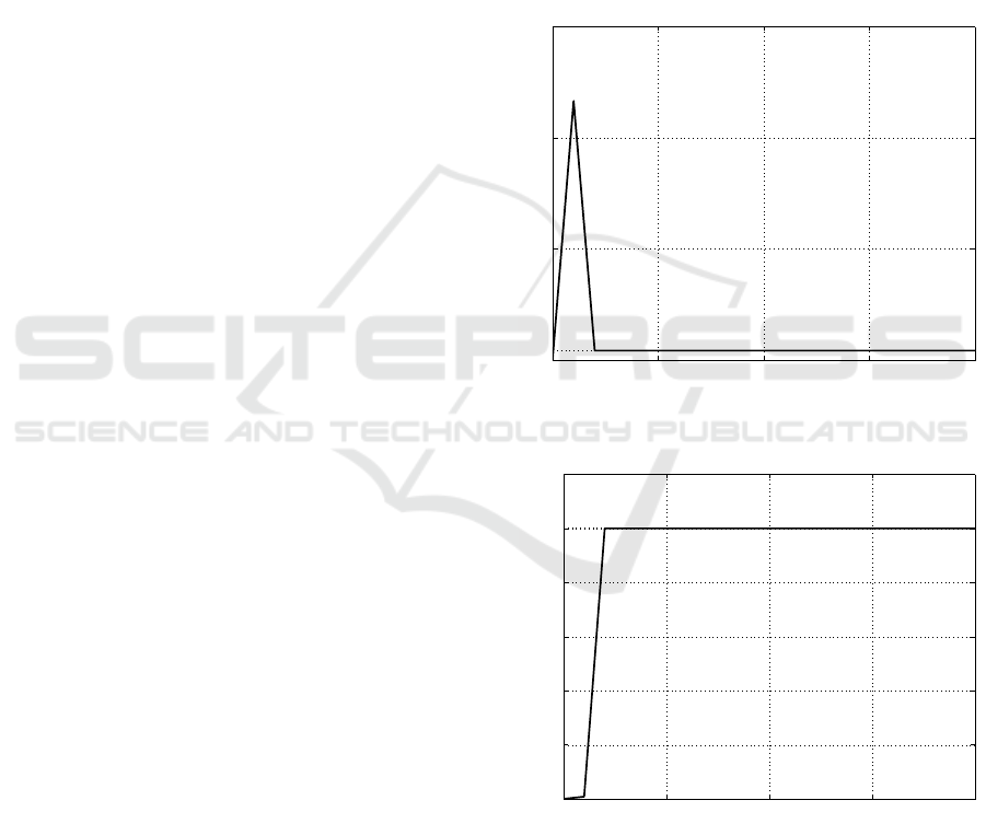
Simulation results obtained for the first case (c =
8.4 · 10
−6
N m s/rad and k = 2.5 · 10
−3
N m/rad) are
depicted in Figure 2 for the damping coefficient c, and
in Figure 3 for the elastic one k.
0 0.5 1 1.5 2
0
1
2
x 10
−4
Time (s)
Parameter c
Figure 2: Time evolution of the estimated value c.
0 0.5 1 1.5 2
0
0.5
1
1.5
2
2.5
3
x 10
−3
Time (s)
Parameter k
Figure 3: Time evolution of the estimated value k.
The solid lines denote the estimations evolution,
the dotted lines correspond to the true values of the
parameters, plotted as a reference. As expected, the
algorithm converges. Moreover, from Figures 4 and
5 that depict the estimation errors for parameter c and
K respectively after 5s (t ∈ [5, 10]s), it is possible to
Dynamic Estimation of Visco-elastic Mechanical Characteristics of Biological Samples under Micro Manipulation
507
5 6 7 8 9 10
0
0.5
1
1.5
2
2.5
3
3.5
x 10
−14
Time (s)
Estimation error on parameter c
Figure 4: Estimation error on parameter c after the transient.
5 6 7 8 9 10
−3.5
−3
−2.5
−2
−1.5
−1
−0.5
0
x 10
−13
Time (s)
Estimation error on parameter k
Figure 5: Estimation error on parameter k after the transient.
0 0.5 1 1.5 2
0
1
2
3
4
5
6
7
8
9
x 10
−3
Time (s)
Parameter c
Figure 6: Time evolution of the estimated value c.
0 0.5 1 1.5 2
0
1
2
3
4
5
6
7
8
x 10
−4
Time (s)
Parameter k
Figure 7: Time evolution of the estimated value k.
5 6 7 8 9 10
−6
−5.5
−5
−4.5
−4
−3.5
−3
−2.5
−2
−1.5
x 10
−14
Time (s)
Estimation error on parameter c
Figure 8: Estimation error on parameter c after the transient.
5 6 7 8 9 10
0
0.2
0.4
0.6
0.8
1
1.2
1.4
x 10
−13
Time (s)
Estimation error on parameter k
Figure 9: Estimation error on parameter k after the transient.
ICINCO 2018 - 15th International Conference on Informatics in Control, Automation and Robotics
508
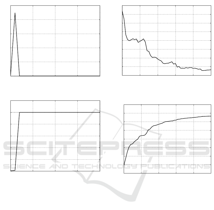
0 0.5 1 1.5 2
0
0.5
1
1.5
2
2.5
x 10
−6
Time (s)
Parameter c
Figure 10: Time evolution of the estimated value c.
0 0.5 1 1.5 2
0
0.5
1
1.5
2
2.5
3
x 10
−5
Time (s)
Parameter k
Figure 11: Time evolution of the estimated value k.
observe that the convergence is very fast, being the
order of magnitude of the errors 10
−14
for c and 10
−13
for k.
For the second case (c = 8.4 · 10
−3
N m s/rad and
k = 2.5 · 10
−6
N m/rad), the simulation results are de-
picted in Figure 6 for the damping coefficient c, and
in Figure 7 for the elastic one k. Again, the solid li-
nes refer to the estimations evolution while the dotted
ones are the true reference values.
Also in this case the fast convergence of the al-
gorithm can be confirmed observing Figure 8 and Fi-
gure 9: the order of magnitude of the errors, after 5s,
(t ∈ [5, 10]s), is equal to the previous case.
The results obtained by simulation of the third
case (c = 8.4 · 10
−11
N m s/rad and k = 2.5 · 10
−5
N
m/rad) are reported in Figure 10 for the damping coef-
ficient c, and in Figure 11 for the elastic one k, where
the solid lines mark the estimations evolution and the
dotted lines denote the true values of the parameters.
5 6 7 8 9 10
0
0.5
1
1.5
2
2.5
3
3.5
4
x 10
−16
Time (s)
Estimation error on parameter c
Figure 12: Estimation error on parameter c after the tran-
sient.
5 6 7 8 9 10
−3.5
−3
−2.5
−2
−1.5
−1
−0.5
0
0.5
x 10
−15
Time (s)
Estimation error on parameter k
Figure 13: Estimation error on parameter k after the tran-
sient.
The time evolutions of the errors are plotted in Fi-
gure 12 and Figure 13. The same considerations as
in the previous case can be performed, with the errors
even smaller than in the two cases above.
6 CONCLUSIONS
In this paper, the possibility of using a recently con-
structed micro gripper device for the estimation of the
elastic and the damping coefficients of a sample ele-
ment by pinching it is proved. A classical forgetting
factor based recursive least squares algorithms for the
parameter estimation is proposed, showing how it is
possible to obtain the values of the parameters wit-
hout the necessity of a specific testing operation, but
also during any operative conditions for the gripper.
From the methodological point of view, a successive
Dynamic Estimation of Visco-elastic Mechanical Characteristics of Biological Samples under Micro Manipulation
509

step is the design of a high-performance algorithm for
the parameters estimation, more robust with respect
of the presence of noise and of model parameters un-
certainties.
REFERENCES
Bagolini, A., Bellutti, P., Di Giamberardino, P., Rudas,
I.J.and DAndrea, V., Verotti, M., Dochshanov, A., and
Belfiore, N. (2018). Stiffness characterization of bi-
ological tissues by means of mems-technology based
micro grippers under position control. In Mechanisms
and Machine Science, volume 49, pages 939 – 947.
Bagolini, A., Ronchin, S., Bellutti, P., Chiste, M., Ver-
otti, M., and Belfiore, N. (2017). Fabrication of no-
vel mems microgrippers by deep reactive ion etching
with metal hard mask. IEEE J. Microelectromechani-
cal Syst., 26:926 – 934.
Boonvisut, P. and C¸ avus¸o
ˇ
glu, M. C. (2013). Estimation of
soft tissue mechanical parameters from robotic mani-
pulation data. IEEE/ASME Transactions on Mecha-
tronics, 18(5):1602–1611.
Cao, S., Luo, Z., and Quan, C. (2015). Estimation of an
objects physical parameter by force sensors of a dual-
arm robot. In Proceedings of the 2015 IEEE Confe-
rence on Robotics and Biomimetics.
Cecchi, R., Verotti, M., Capata, R., Dochshanov, A., Brog-
giato, G. B., Crescenzi, R., Balucani, M., Natali, S.,
Razzano, G., Lucchese, F., et al. (2015). Develop-
ment of micro-grippers for tissue and cell manipula-
tion with direct morphological comparison. Microma-
chines, 6(11):1710–1728.
Choi, D.-K. (2016). Mechanical characterization of biolo-
gical tissues: Experimental methods based on mathe-
matical modeling. Biomedical Engineering Letters,
6(3):181–195.
Di Giamberardino, P., Bagolini, A., Bellutti, P., Rudas, I. J.,
Verotti, M., Botta, F., and Belfiore, N. P. (2018). New
mems tweezers for the viscoelastic characterization of
soft materials at the microscale. Micromachines, 9(1).
Edsberg, L. E., Cutway, R., Anain, S., and Natiella, J. R.
(2000). Microstructural and mechanical characteriza-
tion of human tissue at and adjacent to pressure ulcers.
Journal of Rehabilitation Research and Development,
37(4):463–471.
Flacco, F., De Luca, A., Sardellitti, I., and Tsagarakis, N. G.
(2011). Robust estimation of variable stiffness in flex-
ible joints. In in Proc. of 2011 IEEE/RSJ International
Conference on Intelligent Robots and Systems.
Fontanelli, G. A., Ficuciello, F., Villani, L., and Siciliano,
B. (2017). Modelling and identification of the da vinci
research kit robotic arms. In 2017 IEEE/RSJ Interna-
tional Conference on Intelligent Robots and Systems
(IROS), pages 1464–1469.
Gonz
´
alez-Cruz, R. D., Fonseca, V. C., and Darling, E. M.
(2012). Cellular mechanical properties reflect the dif-
ferentiation potential of adipose-derived mesenchy-
mal stem cells. Proceedings of the National Aca-
demy of Sciences of the United States of America,
109(24):E1523–E1529.
Guido, I., Jaeger, M., and Duschl, C. (2011). Dielectrop-
horetic stretching of cells allows for characterization
of their mechanical properties. European Biophysics
Journal, 40(3):281–288.
Kiss, M. Z., Varghese, T., and Hall, T. J. (2004). Viscoelas-
tic characterization of in vitro canine tissue. Physics
in Medicine and Biology, 49(18):4207–4218.
Lee, S. D. and Jung, S. (2016). A recursive least square ap-
proach to a disturbance observer design for balancing
control of a single-wheel robot system. 2016 IEEE In-
ternational Conference on Information and Automa-
tion (ICIA), pages 1878–1881.
Ljung, L. (1999). System Identification: Theory for the
User. Prentice Hall, 2nd edition.
Lundquist, C. and Sch
¨
on, T. B. (2009). Recursive identifi-
cation of cornering stiffness parameters for an enhan-
ced single track model. IFAC Proceedings Volumes,
42(10):1726 – 1731. 15th IFAC Symposium on Sy-
stem Identification.
Morrison III, B., Meaney, D. F., and McIntosh, T. K. (1998).
Mechanical characterization of an in vitro device de-
signed to quantitatively injure living brain tissue. An-
nals of Biomedical Engineering, 26(3):381–390.
Nava, A., Mazza, E., Furrer, M., Villiger, P., and Reinhart,
W. H. (2008). In vivo mechanical characterization of
human liver. Medical Image Analysis, 12(2):203–216.
Nava, A., Mazza, E., Kleinermann, F., Avis, N. J., and
McClure, J.and Bajka, M. (2004). Evaluation of
the mechanical properties of human liver and kidney
through aspiration experiments. Technology and He-
alth Care, 12(3):269–280.
Tavakoli, M., Aziminejad, A., Patel, R., and Moallem, M.
(2006). Multi-sensory force/deformation cues for stif-
fness characterization in soft-tissue palpation. Annual
Int. Conference of the IEEE Engineering in Medicine
and Biology Society. IEEE Engineering in Medicine
and Biology Society, pages 837–840.
Vahidi, A., Stefanopoulou, A., and Peng, H. (2005). Recur-
sive least squares with forgetting for online estimation
of vehicle mass and road grade: Theory and experi-
ments. Vehicle System Dynamics, 43(1):31–55.
Verotti, M., Crescenzi, R., Balucani, M., and Belfiore, N. P.
(2015). Mems-based conjugate surfaces flexure hinge.
Journal of Mechanical Design, 137(1):012301.
Verotti, M., Dochshanov, A., and Belfiore, N. P. (2017).
Compliance synthesis of csfh mems-based microgrip-
pers. Journal of Mechanical Design, 139(2):022301.
Wakatsuki, T., Kolodney, M. S., Zahalak, G. I., and Elson,
E. L. (2000). Cell mechanics studied by a reconsti-
tuted model tissue. Biophysical Journal, 79(5):2353–
2368.
Wilkening, A. and O., I. (2014). Estimation of mass para-
meters for cooperative human and soft-robots as basis
for assistive control of rehabilitation devices. In Pro-
ceedings of the RAAD 2014, 23rd International Con-
ference on Robotics in Alpe-Adria-Danube Region.
ICINCO 2018 - 15th International Conference on Informatics in Control, Automation and Robotics
510
