
A Guidance and Control Law for Autonomous Formation of
Quadrotors
Xun Zhu and Shuguang Zhang
1
School of Transportation Science and Engineering, Beihang University, Beijing 100191, China
Keywords: Formation flying, Quadrotor, Relative kinematic, Formation algorithm.
Abstract: Formation flying means two or more flight vehicles maintain an organizational flight mode. In autonomous
formation, the guidance is normally divided into formation configuration and task assignment. This paper is
focused on the formation configuration of quadrotors from their initial random positions to an expected
configuration in response of the leader quadrotor. Based on the position and velocity of the leader, the
formation controller will generate the guidance and control instructions from the relative dynamic system.
The updated positions of the followers are compared with the expected positions and furtherly processed by
PI controllers to form speed instructions for the followers, and feedforward controllers are included to shape
commands to provide better tracking performance. Simulations with five quadrotors result show that the
designed guidance and control algorithm can help quickly achieve and keep the desired formation
configuration even to follow complex motions of the leader quadrotor.
1 INTRODUCTION
The multi rotor unmanned aerial vehicle (UAV), as
an important member of the UAV family, has been
evolving rapidly with the development of the control
theory and high technology (Giulietti F, 2005).
Compared with fixed wing unmanned aerial vehicle
and unmanned helicopter, the multi rotor aircraft has
the advantages in terms of vertical take-off and
landing, hovering, simple mechanical structures, easy
maintenance, flexible operability and so on, in spite
of the disadvantage of poor load capability due to
limits in blade size, speed, and flapping. Therefore,
the idea of multi UAV cooperative formation to
accomplish complex mission has been proposed to
employ its potential value while avoid the
disadvantage (Sun N P, 2014; Samaneh H S, 2015).
Multi UAV cooperative formation flying has the
following advantages over single UAV (Escareno J,
2013; Rudio J D 2014):
(1) Redundancy is increased, because any UAV in
the formation can take the place of the others;
(2) Formation flying is more adaptive to complex
tasks;
(3) Information perceived in formation is more
stereoscopic and more accurate
In autonomous formation, the guidance can be
divided into two phases of formation configuration
and task assignment, in which the formation
configuration can be further divided into three sub-
phases of configuration generating, configuration
keeping and configuration adjustment. Current
formation control methods include behaviour mode
based formation, ‘leader-follower’ structure based
formation, virtual structure based formation, artificial
potential field based formation, etc (
Salim N D, 2014;
Karimoddini A, 2013
), as compared in Table 1.
The behaviour mode based formation divides the
behaviour response of each member to its input
information into a number of fixed modes, and
completes formation control by assigning weight. In
the ‘leader-follower’ structure based formation, the
follower sense the information of the leader and form
and keep the configuration by changing its speed. The
virtual structure based formation let the members in
formation follow their respective trajectories by
defining a virtual leader. The artificial potential field
based formation keep the configuration and avoid
collision by imitating the repulsion and gravitation
between particles in a molecular structure.
204
Zhu, X. and Zhang, S.
A Guidance and Control Law for Autonomous Formation of Quadrotors.
In 3rd International Conference on Electromechanical Control Technology and Transportation (ICECTT 2018), pages 204-209
ISBN: 978-989-758-312-4
Copyright © 2018 by SCITEPRESS – Science and Technology Publications, Lda. All rights reserved
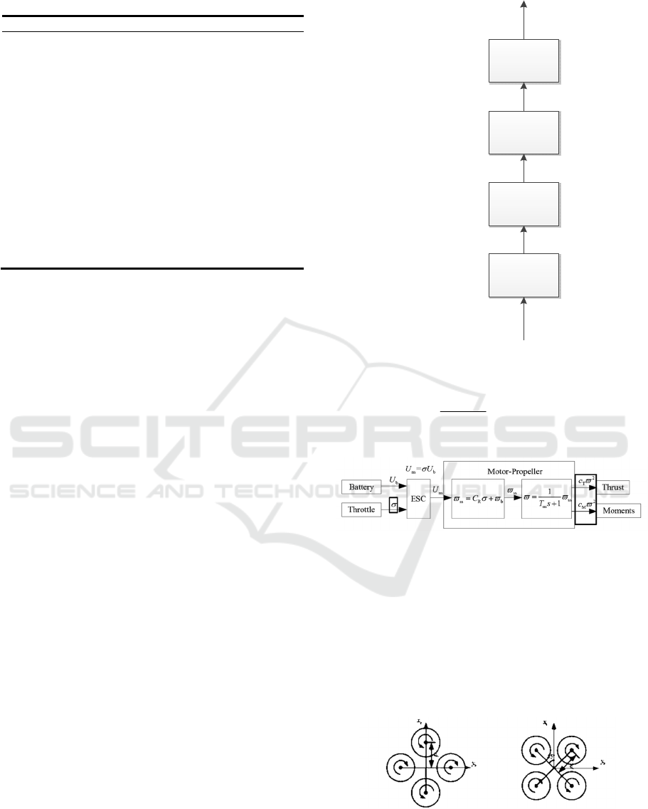
Table 1: Current mainstream formation algorithms
Al
g
orithm Advanta
g
es Disadvanta
g
es
Behaviour
mode
Formation
flexibility;
High reliability;
Strong robustness
Poor formation
keeping
performance
Leader-
follower’
structure
Simple principle;
Easy to
implement
Poor
environmental
adaptability;
Poor reliability
Virtual
structure
Accurate
formation keeping
Hard to expand
Artificial
potential
fiel
d
High reliability
Slow response
In this paper, to achieve good formation flexibility
and keeping performance, while to be easy to
implement, a guidance and control law for
autonomous formation of quadrotors is based on
combination of PI control and feedforward control,
and the followers track the guidance instructions
generated by the formation controller in order to keep
the formation configuration.
2 MODEL DESCRIPTION
The quadrotors in this paper are small and driven by
batteries. Besides the rotors, all airframe parts are
taken as rigid. So, the control models include rigid
body kinematics model, rigid body dynamic model,
control allocation model and power system model as
shown in Figure 1.
2.1 Power system model
The input and output relation of the battery, throttle,
ESC and motor is described by the power system
model. Among them, the motor throttle
σ
is input,
the motor speed
ϖ
is output,
m
T
is the dynamic
response constant of motor. The power system model
is shown in Figure 2, and the mathematical model is
described as:
rigid body
kinematics
model
rigid body
dynamic model
control
allocation
model
powersystem
model
Position and attitude
Veloc ity and angu lar velocity
Force and moment
Propeller speed
PWM
Figure 1: Quadrotor control model
1
()
1
Rb
m
C
Ts
ϖσϖ
=+
+
(1)
Figure 2: Signal transmission diagram of power system
2.2 Control allocation model
The input and output relation of the motor speed and
force and moment is described by the control
allocation model. There are two ways to control
distribution of the ‘
+
’ configuration and the ‘
×
’
configuration, as shown in Figure 3.
Figure 3: The ’
+
’ configuration and ‘
×
’ configuration
A Guidance and Control Law for Autonomous Formation of Quadrotors
205
For the ‘
+
’ configuration quadrotor, the
mathematical model is as follows:
2
1
2
2
2
3
2
4
00
00
TT T T
xTT
yT T
zMMMM
fcccc
dc dc
dc dc
ccc c
ϖ
τ
ϖ
τ
ϖ
τ
ϖ
⎡⎤
⎡⎤⎡ ⎤
⎢⎥
⎢⎥⎢ ⎥
−
⎢⎥
⎢⎥⎢ ⎥
=
⎢⎥
⎢⎥⎢ ⎥
−
⎢⎥
⎢⎥⎢ ⎥
−−
⎢⎥
⎣⎦⎣ ⎦
⎣⎦
(2)
For the’
×
’ configuration quadrotor, the
mathematical model is as follows:
2
1
2
2
2
3
2
4
2222
2222
22 2 2
22 2 2
TTTT
TTTT
x
y
TT T T
z
MMM M
cccc
f
dc dc dc dc
dc dc dc dc
ccc c
ϖ
τ
ϖ
τ
ϖ
τ
ϖ
⎡⎤
⎢⎥
⎡⎤
⎡⎤
⎢⎥
−−
⎢⎥
⎢⎥
⎢⎥
⎢⎥
⎢⎥
=
⎢⎥
⎢⎥
⎢⎥
⎢⎥
−−⎢⎥
⎢⎥
⎢⎥
⎢⎥
⎣⎦
⎣⎦
⎢⎥
−−
⎣⎦
(3)
Where,
f
is the total tension acting on the body,
while
x
τ
,
y
τ
, and
z
τ
are the moments produced by
propellers along the pitching, roll and yaw axes
respectively.
2.3 Control rigid body model
The control rigid body model contains dynamic and
kinematic parts to determine the Euler angles
,,
θφψ
as in the following mathematical model:
33
[]
()
ee
b
bbb T
drag
bb b
a
pv
W
f
vvgReeKv
m
JJG
ω
ω
ωω ω τ
=
Θ=
=− × + − −
=− × + +
&
&
&
&
(4)
Where,
p
,
v
,
Θ
,
ω
represent position, attitude
angle and angular velocity respectively, the left tag e
is expressed in the inertial system and the left tag b is
expressed in the body coordinate system. The
W
is
the coordinate transformation matrix of the body
coordinate system to the inertial system. The
ω
and
J
are the mass and inertia of the quadrotor.
a
G
is the
gyroscopic moment and it is overlooked here. All
these quantities are vector forms.
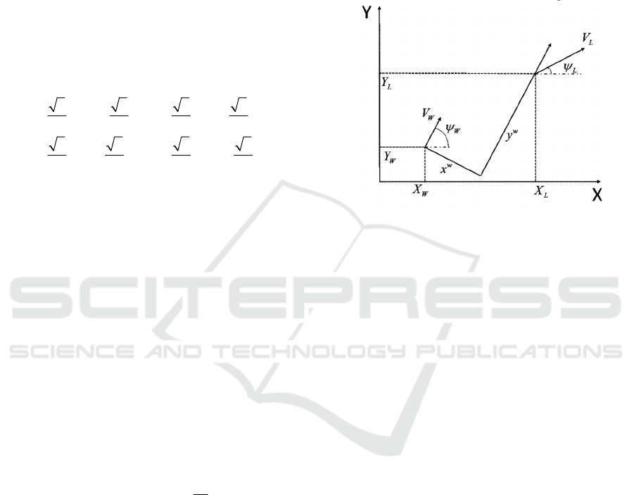
3 FORMATION ALGORITHM
3.1 Formation objective
The formation configuration is defined in the leader’s
speed coordinate system as
w
x
and
w
y
, it can also
be converted to distance and azimuth angle. The
relative kinematic model is shown in Figure 4.
Figure 4: Geometric relation diagram of formation flying
The mathematical model is described as the
following model:
cos( )
sin( )
ww
LLWWW
ww
LLWW
xV yV
yV x
ψψ ψ
ψψ ψ
=−+−
=−−
&
&
&
&
(5)
In the inertial coordinate system, the expected
position of followers can be computed through the
measured leader’s position and relative kinematic
relational expression as:
.
.
.
.
sin cos
cos sin
ww
WEx L L L
ww
WEx L L L
Wx Ex Lx
Wy Ex Ly
YYx y
XXx y
VV
VV
ψψ
ψψ
=− −
=− −
=
=
(6)
The state error of the follower can be calculated
by its expected state and current state, as shown in
Figure 5.
ICECTT 2018 - 3rd International Conference on Electromechanical Control Technology and Transportation
206
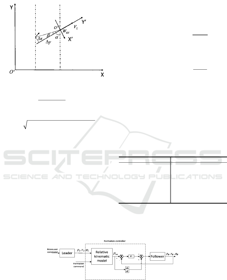
Figure 5: Expected and current states of the follower
.
.
22
..
.
.
arctan
()()
cos
sin
WEx w
WEx w
L
WEx w WEx w
w
w
xWxExWxLxWx
yWyExWyLyWy
YY
XX
DX X YY
xxx D
yyy D
vV V V V
vV V V V
α
βαψ
β
β
−
=
−
=−
=−+−
Δ= − =
Δ= − =
Δ= − = −
Δ= − = −
(7)
The control objective is for the follower to fly
from current state to the expected state with minimal
errors:
( , , , ) (0, 0, 0, 0)
xy
xyv vΔΔΔ Δ ≡
(8)
3.2 Formation algorithm
To achieve the above control objective, the formation
controller is designed according to the forward and
lateral channels.
(1) The forward channel. The control amount is
x
Δ
, and the differential effects of follower’s
expected position is added to the speed control as a
feedforward control:
.
0
t
WEx
Wxc xp xl
dX
Vkxkxdt
dt
=Δ+ Δ+
∫
(9)
(2) The lateral channel. Similar to the forward
channel, the lateral control is as:
.
0
t
WEx
Wyc yp yl
dY
Vkykydt
dt
=Δ+ Δ+
∫
(10)
4 SIMULATIONS
The control structure of the bottom adopts double
loop PID, the formation controller of the top adopts
the combination of PI and position instruction
differential feedforward. The block diagram of the
formation control structure is shown in Figure 6.
The parameters of the quadrotor used in the
simulation are shown in Table 2.
Table 2: Quadrotor parameters
Parameter Value Parameter Value
/mkg
1.15
T
c
5
1.57*10
−
/lm
0.177
M
c
7
7.5*10
−
2
/
x
I
kg m⋅
0.0109
2
/
z
I
kg m⋅
0.021
2
/
y
I
kg m⋅
0.0109
drag
K
0.0013
Figure 6: Block diagram of formation control
A Guidance and Control Law for Autonomous Formation of Quadrotors
207
4.1 Simulations of single quadrotor
control
To verify the single quadrotor control law, the initial
position of quadrotor is set to
(0,0,3)
m and the
initial state of quadrotor is hover. The quadrotor starts
from the initial position and tracks the given
trajectory instructions. The 3D graphs of trajectory
tracking are shown in Figure 7.
Figure 7: 3D graph of trajectory tracking
It can be seen from Figure 7, the actual tracking
trajectory is approximately coincident with the
desired trajectory, the height changes when the
quadrotor turns, but the change is so small that can be
ignored.
4.2 Formation flight simulation of five
quadrotors
To verify the performance of multi aircraft formation,
five quadrotors are taken as examples. Table 3
presents the initial and desired formation position of
five quadrotor, followers read leader for reference to
guide. The detailed formation configuration is shown
in
Figure
8.
Table 3: Initial and desired position for five quadrotor
formation
Quadrotor
000
,,/
x
yz m
,, /
x
yzm
ΔΔΔ
Leader
0, 0, 3
/
Follower 1
2, 3, 3−
1, 1, 0−−
Follower 2
1, 2 , 3−−
2, 2,
0
−−
Follower 3
2, 1, 3−−
1, 1, 0−
Follower 4
1, 4 , 3−−
2, 2, 0−
Figure 8: Five quadrotor formation configuration
In order to test the formation effect of various
motion situation in the leader quadrotor, let the leader
quadrotor carry out all kinds of movement including
uniform motion, uniform transmission motion in the
forward and lateral directions, curvilinear motion and
so on. Speed command and actual speed response of
the leader quadrotor in the forward and lateral
directions is shown in Figure 9.
Figure 9: Speed command and actual speed response of the
leader quadrotor in two direction
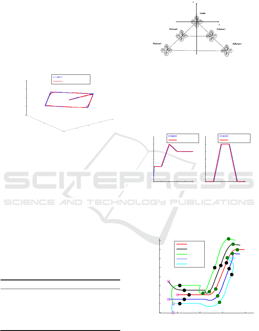
Figure 10 gives the result of the simulated five
quadrotor formation.
Figure 10: Five quadrotor formation configuration
As can be seen from Figure 10, in the forward and
lateral directions, four following quadrotors
accurately reach the desired positions in the formation.
-10
-5
0
5
10
-10
0
10
2
2.5
3
3.5
4
X/ m
Y/m
Z/m
Expected trajectory
Actual trajectory
0 5 10 15 20 25
0
0.1
0.2
0.3
0.4
0.5
0.6
t/s
Vx/(m/s)
Expected speed
Actual speed
15 20 25 30 35 40
0
0.2
0.4
0.6
0.8
1
1.2
t/s
Vy/(m/s)
Expected speed
Actual speed
0 5 10 15
-4
-2
0
2
4
6
8
10
12
X/ m
Y/m
Leader
Follower1
Follower2
Follower3
Follower4
ICECTT 2018 - 3rd International Conference on Electromechanical Control Technology and Transportation
208
The altitude and yaw angle channel is decoupled, and
the change is so small that it is negligible.
The variation of speed in the forward and lateral
directions of four follower quadrotor and the leader
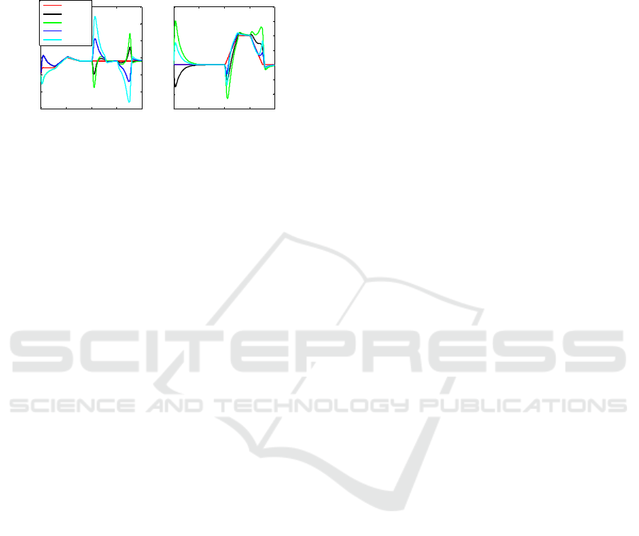
quadrotor in the formation is shown in Figure 11.
Figure 11: The speed in the forward and lateral
directions of five quadrotors
As can be seen from Figure 10 and Figure 11,
leader and followers form a stable formation at about
7 seconds. After that, formation configuration can be
maintained nice in the case of a variety of movements
in the leader quadrotor. Among them, under the
condition of unidirectional linear uniform motion and
uniformly variable motion of the leader, the speed in
the forward and lateral directions of any follower will
converge to the speed value of the leader. Under the
condition of curvilinear motion of the leader, the
speed of the follower in the outer circle will become
larger in order to keep the formation configuration,
the speed of the follower in the inner circle will
become smaller and even move in reverse in order to
keep the formation configuration. In this process,
although the speed of any follower will not converge
to the speed value of the leader, the formation
configuration has been kept very well. If the leader
quadrotor is allowed to continue to do circular motion,
the speed in the forward and lateral directions of any
follower will converge to a corresponding value.
5 CONCLUSIONS
This paper uses the combination of classical PI
control and feedforward control to design the
guidance law of autonomous formation of multiple
quadrotors. Simulation results of single quadrotor
trajectory tracking and formation of five quadrotors
are given. The accuracy and response speed of
trajectory tracking are verified. The formation control
law as a top layer controller commands the position
and controller of single quadrotor. Simulation results
show that the guidance instruction generated by the
presented formation control law can guide the
followers to form expected formation configuration
and keep the formation quite well.
REFERENCES
Giulietti F, Innocenti M, Napolitano, et al. Dynamic and
control issues of formation flight[J]. Aerospace Science
and Technology, 2005, 36(9): 65-71.
Sun N P. An alternative flocking algorithm with additional
dynamic conditions[C]//Ninth International Conference
on Broadbrand and Wireless Computing. Guangdong:
IEEE, 2014: 491-496.
Samaneh H S. Semi-flocking algorithm for motion control
of mobile sensors in large-scale surveillance
systems[J]IEEE Transactions on Cybernetics, 2015,
45(1):129-135.
Escareno J, Salazar S, Romero H. Trajectory control
quadrotor subject to 2D wind disturbances: robust-adap-
tive approach[J]. Journal of Intelligent and Robotic
Systems: Theory and Applications, 2013, 70(1-4):51-63.
Rudio J D, Cruz J H P, Zamudio Z, et al. Comparison of
two quadrotor dynamic models[J]. IEEE Latin America
Transactions, 2014, 12(4): 531-537.
Salim N D, Derawi D, Abdullah S S, et al. PID plus LQR
attitude control for hexarotor MAV[C].IEEE
International Conference on Industrial Technology
(ICIT). Busan, Korea, 2014:85-90.
Karimoddini A, Lin H, Chen B M. Hybrid three-
dimensional formation control for unmanned
helicopters[J]. Automatica, 2013, 49(2):424-433.
0 10 20 30 40
-1
-0.5
0
0.5
1
1.5
2
t/s
Vx/(m/s)
Leader
Follower1
Follower2
Follower3
Follower4
0 10 20 30 40
-1.5
-1
-0.5
0
0.5
1
1.5
2
t/s
Vy/(m/s)
A Guidance and Control Law for Autonomous Formation of Quadrotors
209
