
MOCONT LOCATION MODULE: A CONTAINER LOCATION
SYSTEM BASED ON DR/DGNSS INTEGRATION
Joseba Landaluze, Victoria del Río, Carlos F. Nicolás, José M. Ezkerra, Ana Martínez
IKERLAN Research Centre, Arizmendiarrieta 2, 20500 Arrasate/Mondragon, The Basque Country (Spain)
Keywords: DR/DGNSS, DR, GPS, DGPS, inertial navigation system, location system
Abstract: The problem of identifying and adequately positioning containers in the terminal yard during handling with
Reach Stackers still remains to be solved in an appropriate manner, while this is extremely important in
making the identification and positioning operations automatic. A precise knowledge in the Terminal
Operating System (TOS) of such data in Real Time would have considerable economic impact on the
logistic treatment of operations. The MOCONT system sets out to provide a solution to this lack. In
particular, the MOCONT Location Module establishes the position of the container in the yard while it is
being handled by a Reach Stacker. This system is based on the integration of the Differential Global
Navigation Satellite System (DGNSS) with a Dead Reckoning (DR) inertial system. This article presents the
general characteristics of the MOCONT Location Module, its structure, and the structure of data fusion,
besides some results obtained experimentally.
1 INTRODUCTION
The problem of localising the containers in the yard
of container terminals had been partially solved for
terminals equipped with huge machines, such as
Rubber Tyre (RTG) and Rail Mounted Gantry
Cranes (RNG) or even Straddle Carriers, but is still a
problem for those terminals equipped with Reach
Stackers or Front Loaders. Moreover, the automatic
identification of containers on board the handling
machine is still a problem remaining to be solved.
The European projects MOCONT (“Monitoring
the yard in container terminals”, IST-1999-10057)
and MOCONT-II (“Monitoring the yard in container
terminals – Trials”, IST-2001-34186), aimed at
providing a system to track the containers in the yard
in Real Time. The projects aimed at developing a
system that automatically identified containers and
localised them when moved by small machines,
called Reach Stackers.
This paper presents the Location Module of the
MOCONT system, developed in said European
projects, and more particularly, the development of
the inertial navigation system or Dead Reckoning
(DR) system. The Location Module is based on the
integration of a Differential Global Navigation
Satellite System (DGNSS) and an inertial DR
system. Data are integrated by means of a Kalman
Filter. This system reckons the position of the
vehicle at all times, improving estimates supplied by
the DGNSS. The exact position of the container is
determined by means of a transformation of
coordinates from the vehicle body since the length
and angle of inclination of the boom are known. The
system is particularly useful when the GNSS does
not supply quality data or is interrupted, due to few
satellites being accessible, multipath phenomena or
due to working inside container canyons or in dark
areas. The DR inertial system is able to continue
estimating vehicle position with precision for short
time intervals, with bounded errors, until GNSS
signals with sufficient quality are available.
In the literature, different structures of inertial
systems appear for land vehicles. The most common
case is the use of a sensor for rotation speed of yaw
angle and odometric information obtained from
vehicle wheels (Aono, 1999; Ramjattan, 1995).
Other redundant sensors are often used to help, each
being different depending on the type of vehicle and
application in question (Aono, 1999; Zhang, 1999).
In some cases, especially in vehicles for agricultural
purposes, a digital compass or a geomagnetic
direction sensor are used instead of a yaw angle
speed gyroscope (Benson, 1998; Zhang, 1999). In
order to avoid errors, which may be introduced by
odometric sensors on wheels due to slipping,
Sukkarieh (1999) proposes an Inertial Measurement
Unit (IMU), comprising three accelerometers, three
227
Landaluze J., del Río V., Nicolás C., Ezkerra J. and Martínez A. (2004).
MOCONT LOCATION MODULE: A CONTAINER LOCATION SYSTEM BASED ON DR/DGNSS INTEGRATION.
In Proceedings of the First International Conference on Informatics in Control, Automation and Robotics, pages 227-234
DOI: 10.5220/0001132802270234
Copyright
c
SciTePress

gyroscopes and two pendular gyroscopes, by which
vehicle acceleration and yaw and tilt rotation speeds
are obtained. Rogers (1999) presents an inertial
system consisting of a low cost fibre optic rate
gyroscope and of a radar ground speed sensor.
Due to the specifications of the MOCONT
project, according to which it was not possible to
change the structure of the Reach Stacker machines
and nor was it possible to install encoders in the
wheels to obtain odometric information, initially a
structure based on a triad of accelerometers and a
triad of solid state gyroscopes was selected.
Although this set up may be valid for on-road
vehicles, once field data were obtained for a Reach
Stacker in normal work tasks, it was concluded that
this set up was not valid for such a machine; due to
the low speeds and considerable degree of vibration
to which this machine is subject during operations,
the accelerometers did not provide information on
machine movements on the yard, and only the yaw
rate ant tilt rate gyroscope signals could be used
(Landaluze, 2003). Therefore, a sensor structure
similar to that proposed in (Rogers, 1999) was
chosen. Finally, since a subcentimetric receiver was
replaced by a submetric receiver, and taking into
account the “non-collocation” between the Reach
Stacker chassis sensors and the GPS antenna, fitted
on the highest point of the Reach Stacker boom,
sensoring was completed with a digital compass.
This paper firstly presents an overview of the
MOCONT project, followed by an explanation of
the structure of the Location Module in the
MOCONT system. Then follows a description of the
DR inertia system and the Kalman Filter
implemented. Lastly, some experimental results are
shown, as well as a statistical evaluation of the
results obtained by the Location Module of the
MOCONT system in the course of the MOCONT-II
project.
2 OVERVIEW OF THE MOCONT
SYSTEM
The MOCONT project was presented as a new
landmark in the application of telematics in
intermodal transport, especially in the control of
container terminals. The main objective of the
project was to develop a system to identify the
position of containers in the yard in Real Time.
Although said follow-up problem had already been
partially solved in the case of large loading and
unloading cranes (Rubber Tyre RTD, Rail Mounted
Gantry Crane RMG, Straddle Carriers), this was and
is a problem in terminals with Reach Stacker
machines. It was in these machines, therefore, where
the project comes to bear (Figure 1).
The Reach Stacker is an off-road machine used
to handle containers in the terminal yard. It is
characterised by a small body with an extensible
boom (the arm) mounted over of the operator cabin.
It is equipped with a spreader, namely the handling
device used to pick and keep containers by the
machine itself. The Reach Stacker can stack up to
the fourth height (up to the fifth height in case of
empty containers).
Taking into account the main objective of the
project, the MOCONT system should perform the
following operations:
• Identify the container, reading the identification
code when picked up by each Reach Stacker.
• Follow each movement of the container in the
terminal yard while being handled by the Reach
Stacker, recording (i.e., the position of the
container in the yard – row, column, height)
where the container is picked up or released.
• Inform on the position of the container and its
identification without the intervention of human
operators.
YARD
Ship Gate
Buffer
Rail Gate
Buffer
Truck Gate
Figure 1: Overall scheme of a container terminal and Reach Stacher container handling machine.
ICINCO 2004 - ROBOTICS AND AUTOMATION
228
• In Real Time, update the position of any
container handled by a Reach Stacker in the
Terminal Operating System (TOS).
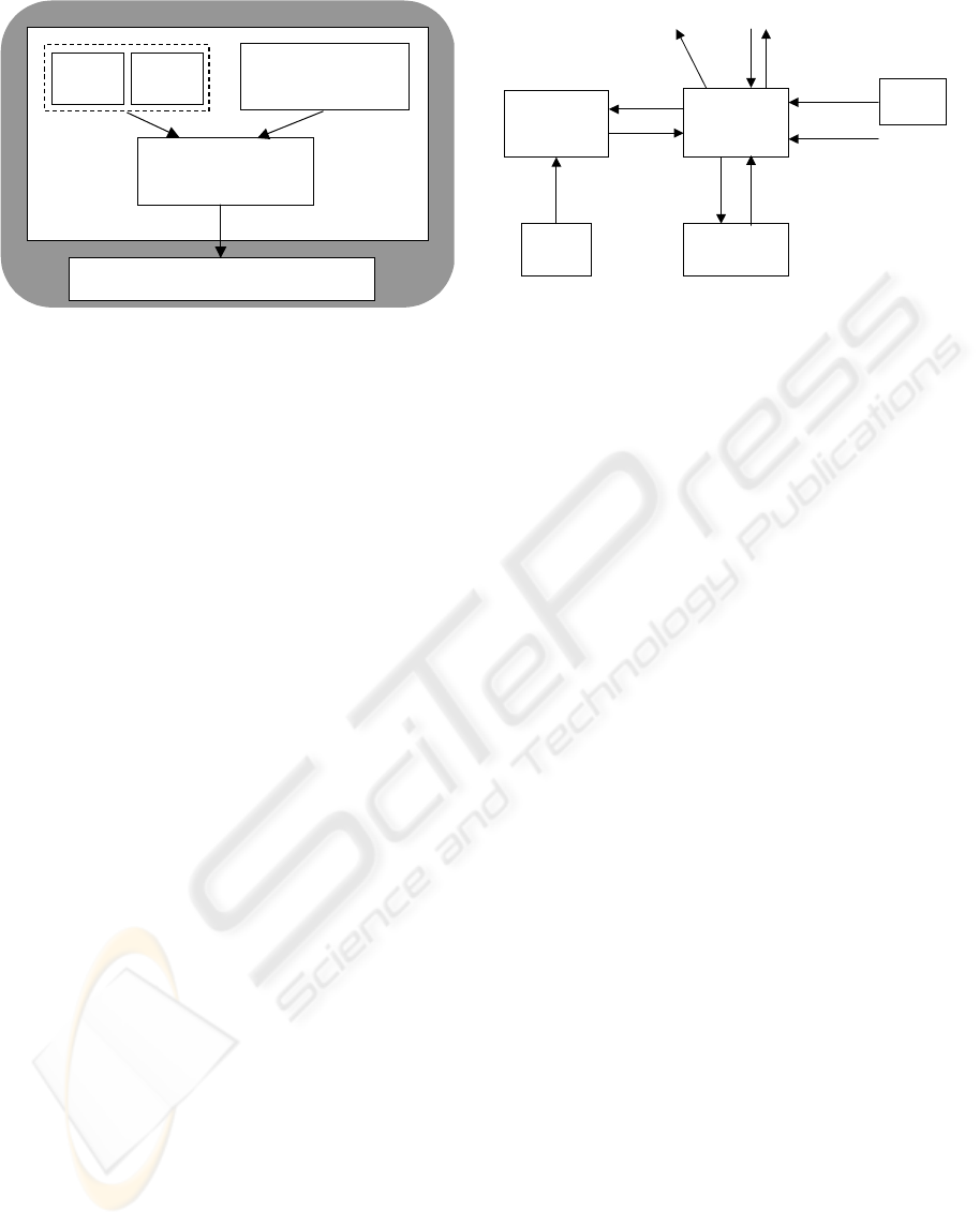
In order to obtain the objectives proposed, the
MOCONT system incorporates three different
modules (Figure 2): the Location Module, the Visual
Identification Module and the Synchronisation and
Communication Module. The Location Module
determines the position of the container in the
terminal yard; the Visual Identification Module
reads the container’s identification code; the
Synchronisation and Communication Module
acquires the identification and position data on the
container and informs the TOS.
3 STRUCTURE OF THE
LOCATION MODULE
The Location Module consists of two subsystems:
the DR subsystem and the DGNSS subsystem. This
last one has two different parts: the GPS receiver
and the GNSS Processing Module.
In the final MOCONT Location Module
Trimble’s Ag132 GPS receiver is used at the heart of
the GNSS and, therefore, of the location system, for
the positioning of the Reach Stacker. The Ag132
GPS receiver combines high-performance GNSS
reception with radio-beacon DGNSS capability in a
single durable waterproof housing, ideal for use in
the yard environment. The receiver uses differential
GNSS to provide sub-metre accuracy.
Differential GNSS requires two or more
receivers. One receiver, called the reference or base
station, is located at a known point to determine the
GNSS measurement errors. This could be housed on
the roof of the main administration buildings, to
allow easy access and constant monitoring. An
unlimited number of AgGPS receivers, sometimes
called rovers, collect GNSS data at unknown
locations onboard each Reach Stacker. Over a radio
band, the reference station broadcasts correction
values, which are applied to the Ag132 GPS receiver
positions. Errors common at both the reference and
rover receivers and then removed from the solution.
The performance of the Ag132 GPS receiver is
improved by direct GNSS augmentation with height
aiding. Height aiding improves the solution by
enhancing satellite visibility, and reducing the
positioning challenge from a three-dimensional to a
two dimensional problem. Using a DTM of the port
and the current location of the Reach Stacker, an
interpolation algorithm provides an accurate
measure of the current ground height. With
knowledge of the Reach Stacker geometry, the boom
extension and boom inclination, the height of the
GNSS antenna on board the vehicle, and indeed the
height of the container carried by the Reach Stacker,
can be continually computed.
In addition, the Location Module provides
complimentary DR augmentation for periods when
GNSS positioning with height aiding is not possible.
The DR subsystem consists of a Processing Unit and
some DR sensors, by means of which the Reach
Stacker position is continuously estimated. The
GNSS Processing Module continually provides the
DR subsystem with the current position from the
Ag132 GPS receiver (in projected UTM
coordinates) and some indication of the quality of
that position fix (by means of a covariance matrix of
the computed parameters). In return the DR
subsystem continually updates the GNSS Processing
Module with the best estimate of the current
position.
The GNSS Processing Module will then pass the
position information to the driver and the rest of the
MOCONT system.
The GNSS Processing Module, which interfaces
with the Ag132 GPS receiver, the DR subsystem,
Terminal Operating System (TOS)
DR Inertial
N
avigation
DGNSS Visual Identification
Synchronisation and
Communication
Middleware
LM VIM
MOCONT
SCM
Figure 2: MOCONT functional architecture.
GNSS
Processing
Unit
Port DTM
Ag132 GPS
Receiver
DR
Processing
Unit
Dis
p
la
y
MOCONT
DR
sensors
Boom
sensors
Figure 3: Scheme and flow data of the Location Module.
MOCONT LOCATION MODULE: A CONTAINER LOCATION SYSTEM BASED ON DR/DGNSS INTEGRATION
229

the boom sensors and the Synchronisation and
Communication Module, has been developed using
the robust and compact AgGPS 170 Field Computer.
The AgGPS 170 is designed to withstand the
environmental extremes that are typical of the
container port environment.
A scheme of the Location Module, with its
components and the flow of data, is shown in Figure
3 and Figure 4. As can be observed, the
communication between the two subsystems of the
Location Module is by means of a CAN bus. The
communication between the GNSS subsystem and
the Synchronisation and Communication Module is
also by another CAN bus (Figure 4). The values
measured by the boom sensors are supplied by the
MOCONT middle-ware through this bus.
4 DR SUBSYSTEM DESIGN
4.1 Description of the DR subsystem
Although initially different sensorings were tested
for the DR subsystem, a sensor structure similar to
that proposed by Rogers (1999) was finally selected.
Likewise, replacing the MS750 subcentimetric GPS
receiver in the final structure of the Location
Module with an Ag132 submetric receiver, made it
necessary to complete sensoring in the DR
subsystem with a digital compass. As a result of
these changes, the final structure used for the DR
subsystem was as follows:
• The DR Processing Module, which consisted of
a sandwich of three PC/104 boards: a CPU
based on a 233 MHz Pentium Processor, an I/O
data acquisition board and a 2-channel CAN
communication board.
• The DR sensor set. This included the following
sensors: a solid state gyroscope to measure the
speed of rotation around the yaw axis; a radar
technology Ground Speed Sensor, which
provided the forward/backward speed of the
vehicle; a stop/direction sensor, in order to
detect if the vehicle is stopped or not, as well as
the movement direction of the vehicle, forward
or backward; a digital compass, to measure the
vehicle heading angle.
Figure 4 shows the main elements of the
Location Module and the structure of the DR
subsystem. A laptop computer was used to monitor
and configure the DR subsystem, as well as to
collect raw data. Most of the elements of the DR
subsystem were included in two boxes, the Location
Module box and the Heading box, as they appear in
Figure 5.
4.2 DR/DGNSS integration
Although different data fusion algorithms were
tested, a kinematical Kalman Filter was finally
chosen due to its simplicity and the good results
obtained. For the navigation equations, it is assumed
that the vehicle is moving on a tangent-plane, as it
was a point, so the positioning involves locating the
vehicle in cardinal directions: N-S-E-W. Figure 6
shows the local level geographic navigation and the
Gyro
Radar
Sensor
Stop/direct
Sensor
Laptop
Computer
PC/104
DR
Proc. Module
AgGPS 170
GNSS
Processing Module
Ag132
GPS
receiver
24 V
24 V
CAN
CAN
CAN
CAN
RS-232
DR subsystem
GNSS subsystem
MOCONT
Digital
Compass
Figure 4: Elements of the Location Module.
Figure 5: Heading box and Location Module box.
N
E
X
Y
ψ
Figure 6:Local level geographic and body frames.
ICINCO 2004 - ROBOTICS AND AUTOMATION
230
body reference frames. It is assumed that the only
transformation between these two frames is via the
heading angle
ψ
.
The DR navigation system implements a
distance travelled (integrated velocity) and a travel
direction. The distance travelled is referenced to the
body frame, which is then transformed into a local
level geographic navigation frame through the angle
ψ
. This implementation assumes that other vehicle
attitudes, i.e., roll and pitch, are sufficiently small as
to be ignored.
The body referenced velocity is represented as a
nominal velocity v, defined such that the X-
component is along the primary direction of travel,
plus velocity errors as a result of speed sensor scale
factors
v
ε
.
The computed body referenced velocity is
represented as
vB
vvv
ε
⋅+= (1)
where v is the measured or estimated vehicle
velocity.
Assuming that the body to navigation frame
transformation and body-referenced velocity are
approximately constant over a small time interval,
the sampling time, it can be written:
ψεψψ
ψεψψ
sinsinsin
coscoscos
⋅⋅+⋅=⋅=
⋅⋅+⋅=⋅=
vB
vB
vvve
vvvn
&
&
(2)
where
n
&
and e
&
are the velocities in the local frame
and v is the measured vehicle velocity.
The heading angle rate could be expressed as
follows:
ψψψψψ
ε
α
ψ
bVV +
⋅
+
⋅
=
&
(3)
where
ψ
α
: gyroscope gain
ψ
ε
: gyroscope scale factor error
ψ
b : gyroscope bias
ψ
V : measured gyroscope voltage
The speed sensor scale factor error
v
ε
, the
gyroscope scale factor error
ψ
ε
and the gyroscope
bias
ψ
b
are modelled as random-walk processes.
From equations (1), (2) and (3) the continuous-time
state-space realisation for the DR/DGPS is deduced:
vxhy
wuxfx
+=
+
=
)(
),(
&
(4)
where
[
]
′
=
ψ
Vvu ,
[
]
′
=
ψψ
εψε
benx
v
and
w and v are random variables. The augmented
state equations for the DR subsystem can be stated
in direct form or in terms of residual errors, and
therefore the structure of the Extended Kalman Filter
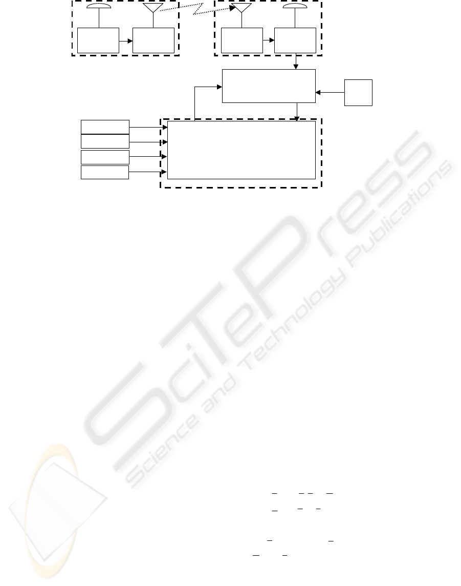
can be deduced, the measurement vectors being:
DGPS
Receiver
Radio
Modem
Radio
Modem
Gyroscope
Speed sensor
Stop/dir sensor
GNSS
Processing Module
n, e, R
UTC,
Φ
,
λ
,h,
PDOP, #sat,
GPS quality
ψ
&
v
ψ
ˆ
,
ˆ
,
ˆ
en
DGPS
Receiver
Base Station
Rover Unit
DR Software Im
p
lementation
Compass
ψ
Extended Kalman Filter
Boom
sensors
Figure 7: DR/DGNSS integration scheme.
MOCONT LOCATION MODULE: A CONTAINER LOCATION SYSTEM BASED ON DR/DGNSS INTEGRATION
231

⎥
⎦
⎤
⎢
⎣
⎡
=
ψ
V
v
ku
)( with a frequency of 200 Hz
⎥
⎥
⎥
⎦
⎤
⎢
⎢
⎢
⎣
⎡
=
ψ
e
n
kz )( with a frequency of 2 Hz
Figure 7 shows the DR/DGNSS integration
scheme. As outputs of the prediction steps of the
Extended Kalman Filter, a vehicle position estimate
is obtained with a frequency of 200 Hz, although the
correction of state estimate is applied with a
frequency of 2 Hz.
5 EXPERIMENTAL RESULTS
Figure 8 shows how all the MOCONT Location
Module elements are fitted in a Reach Stacker. In
the course of the MOCONT project, a system
prototype was tested at the Terminal Darsena
Toscana (TDT) in Livorno (Italy). In the MOCONT-
II project, however, the system was implemented on
8 prototypes tested intensively over a six-month
period at the TDT and at the VTE terminal in Genoa
(Italy), taking a considerable number of data for
statistical analysis.
The main objective of the Location Module is to
locate precisely the container in the terminal yard.
The yard is the surface of the terminal dedicated to
the container storage. It is subdivided into modules,
each one composed of corridors (carriageways used
to move containers within a module and between
different modules) and groups of slots. A group of
slot is referred to as a lane. Lanes are numbered
using capital letters, starting from A. One slot is
uniquely identified within a lane by its yard
coordinates: row, column and height (Figure 1).
Therefore, the container position in the
corresponding slot should be accurately estimated.
During the project MOCONT-II more than 5600
container position messages were collected. Results
presented in the Final Public Report (MOCONT-II,
2004) led to the conclusion that the performance of
the MOCONT Location Module was 99.7% of
correct localisation resulting from the wide set of
trials carried out.
The advantages of the DR subsystem are
highlighted during the work inside container
canyons, and generally, in the work near high stacks
of containers which, on the other hand, are the most
important moments for the correct position
identification as this is when the Reach Stacker is
picking up or releasing a container in a given slot.
Figure 9 shows typical results of a Reach Stacker
handling a container. It corresponds to data collected
in Livorno, where the cases of container canyons
were quite common. The figure shows the GNSS
estimate for the position of the vehicle chassis and
the estimate conducted by the DR subsystem, which
Figure 8: Installation of all elements of the MOCONT Location Module on a Reach Stacker.
ICINCO 2004 - ROBOTICS AND AUTOMATION
232

is transmitted to the GNSS on a frequency of 2 Hz.
North and east relative position components, with
respect to the starting point O, appear. The vehicle
moves forward from the origin O to point A (instant
28 s). It then moves backward to point B (instant 30
s) from where it moves forward once again to point
E (instant 85 s), after having passed through points
C (instant 40 s) and D. It is at point E until instant 91
s, when it then moves backward to point F (instant
104 s). Covariance is not very good (always greater
than 1), but also, between points C and D, it is
approximately 3. As shown in the graph of Figure 9,
when the covariance of the GNSS estimate is
relatively low (about 1), the DR estimate continues
to be in line with that of the GNSS. When the value
of the covariance is large, particularly in the D-E-F
stretch, the DR estimate is based mainly on the
information provided by its own sensors
.
In Figure 10 a detail of results obtained in Genoa
is shown. In Genoa true container canyons rarely
appeared, but sometimes the influence of high stacks
of containers was evident, as in the case shown in
the figure. The movement of the Reach Stacker
starts at the point O, point considered as the origin of
coordinates. The vehicles moves forward to point A
(instant 12 s) and it is stopped at that point until
instant 74 s, when it then moves backward to point B
(instant 78 s). The Reach Stacker is at point B until
instant 106 s. Then it goes forward to point C
(instant 110 s) and after 17 s at that point the vehicle
moves backward to point D (instant 130 s). After 11
s it continues going backward to point E (instant 153
s), changes movement direction and moves forward
to point F (instant 188 s) and then it continues its
travel. As it can be deduced from the figure, the
Reach Stacker performed operations with containers
at points A and C. A container was picked up from a
slot at point A and then it was released in other slot
at point C.
The GNSS data covariance was very bad from
instant 6 s until instant 78 s and from instant 106 s
until instant 110 s (east covariance value higher than
3.5 and north covariance value higher than 9).
Therefore, from point A to point C the GNSS
estimates have poor quality, as it can be observed in
Figure 10, but DR estimates show very well the
movement carried out.
6 CONCLUSIONS
Analysis of a large number of experimental data
obtained in the course of the MOCONT-II project
has proven the success of the MOCONT Location
Module in tasks involving tracking the position of
containers in terminal yards while these are being
handled by the Reach Stackers, recording the slot
(row, column, tier), where the container is picked up
or released. Integration of the Differential Global
Figure 9: Example of experimental results at the TDT terminal in Livorno.
MOCONT LOCATION MODULE: A CONTAINER LOCATION SYSTEM BASED ON DR/DGNSS INTEGRATION
233

Navigation Satellite System (DGNSS) with a Dead
Reckoning (DR) inertial system has been
demonstrated to be effective in estimating the
position of the vehicle and of the container.
Positioning is effective even when working in
container canyons, on the condition that it be for a
limited movement time of some 40 s. Apart from the
general characteristics of the MOCONT system, the
structure of the MOCONT Location Module has
been presented as well as the data fusion diagram.
Likewise, typical experimental data and the final
evaluation of effectiveness are also presented.
ACKNOWLEDGEMENT
The material in this paper has been partially funded
by the European Union under the scope of the
Information Society Technologies programme
(research projects MOCONT: IST-1999-10057 and
MOCONT-II: IST-2001-34186).
REFERENCES
Aono, T., K. Fujii and S. Hatsumoto. 1999. Positioning of
a Vehicle con Undulating Ground Using GPS and
Internal Sensors. T. SICE, vol. 35, no. 8, pp.
1004/1001.
Benson, E.R., T.S. Stombaugh, N. Noguchi, J.D. Will and
J.F. Reid. 1998. An evaluation of a geomagnetic
direction sensor for vehicle guidance in precision
agriculture applications. ASAE paper 983203.
Landaluze, J., V. del Río, A. Milo, J. M. Ezkerra and A.
Martínez. 2003. Desarrollo de un sistema de
localización DR/DGPS para vehículos “off-road”. 5ª
Semana Geomática. Barcelona, 11-14 febrero.
MOCONT-II. 2004. Final Public Report.
www.mocont.org.
Ramjattan, A.N. and P.A. Cross. 1995. A Kalman Filter
Model for an Integrated Land Vehicle Navigation
System. Amy 1995, vol. 48 (no.2), pp. 293-302.
Rogers, R.M. 1999. Integrated DR/DGPS using Low Cost
Gyro and Speed Sensor. ION National Technical
Meeting.
Sukkarieh, S., E.M. Nebot and H.F. Durrant-Whyte. 1999.
A High Integrity IMU/GPS Navigation Loop for
Autonomous Land Vehicle Applications. IEEE
Transactions on Robotics and Automation, vol. 15, no.
3.
Zhang, Q, J.F. Reid and N. Noguchi. 1999. Agricultural
Vehicle Navigation Using Multiple Guidance Sensors.
FSR'99 International Conference on Field and Service
Robotics.
Figure 10: Example of experimental results at the VTE terminal in Genoa.
ICINCO 2004 - ROBOTICS AND AUTOMATION
234
