
EXPLORATIVE UML MODELING
Comparing the Usability of UML Tools
Martin Auer, Ludwig Meyer and Stefan Biffl
Institute of Software Technology and Interactive Systems,
Vienna University of Technology, Favoritenstr. 9-11, A-1040 Vienna, Austria
Keywords:
Usability measures, UML tools, user interface design, UML modeling.
Abstract:
UML tools are used in three main ways: (1) to exploratively sketch key system components during initial
project stages; (2) to manage large software systems by keeping design and implementation synchronized;
and (3) to extensively document a system after implementation.
Professional tools cover (3) to some extent, and attempt to cover (2), but the vast number of languages, frame-
works and deployment procedures makes those tasks all but impossible. By aiming at these two goals, tools
must enforce formal UML language constructs more rigorously and thus become more complicated. They can
become unsuitable for (1).
This paper looks at explorative modeling with the leading UML tool Rational Rose and the open-source
sketching tool UMLet. We define usability measures, assess both tools’ performance for common UML
design tasks, and comment on the consequences for the application of UML tools.
1 INTRODUCTION
The Unified Modeling Language (UML) (Booch
et al., 2005) has become the standard graphical no-
tation in software engineering. Different diagram
types support most phases and workflows of the soft-
ware process, including requirement engineering, de-
sign, implementation and deployment. UML is sup-
ported by a variety of tools trying to deliver on the
elusive promise of computer-aided software engineer-
ing (Eichelberger, 2002).
In practice, UML is applied in three main scenar-
ios. First, UML is the notation of choice when cre-
ating early drafts of requirement specifications, and
software or database designs. Use case diagrams and
design sketches are often created from scratch and
modified over several iterations. The diagrams do not
have to adhere to the strict UML standards; they are
used in an explorative way (Rumbaugh et al., 2004).
Second, in large-scale software engineering en-
vironments, software design and implementation are
kept in sync using sophisticated round-trip engineer-
ing tools (Medvidovic et al., 1999). These are capa-
ble of generating code stubs from design blueprints,
of generating diagrams from existing code, and of
propagating changes from one artifact to others. The
models and diagrams must conform to formal crite-
ria; only in this way are the tools able to handle the
relations between diagrams and code.
Finally, such round-trip engineering tools are also
able to effortlessly generate UML documentation
from large existing code bases. This is an easy way
to provide clients with a seemingly vast amount of
system documentation, which is often required by
contract but seldom maintained consistently during a
project’s lifetime.
This paper looks at the first application scenario—
UML sketching—, and more precisely at tools sup-
porting the sketching process. We argue that UML
is applied differently in that scenario, and that tools
aimed at providing formal UML support and complex
round-trip-engineering might be inadequate to cover
it. We compare the commercial UML tool Ratio-
nal Rose to the open-source tool UMLet (Auer et al.,
2003) and quantitatively assess the tools’ usability for
explorative sketching. Rational Rose was chosen be-
cause it is the leading UML modeling tool in large-
scale industrial environments. UMLet, on the other
466
Auer M., Meyer L. and Biffl S. (2007).
EXPLORATIVE UML MODELING - Comparing the Usability of UML Tools.
In Proceedings of the Ninth International Conference on Enterprise Information Systems - ISAS, pages 466-473
DOI: 10.5220/0002351804660473
Copyright
c
SciTePress

hand, provides a low-complexity user interface and
thus a baseline for our comparison.
We assess the tools’ usability by measuring the
complexity of 16 common UML modeling patterns,
or use cases. Examples for such use cases are
changing class attributes, modifying dependencies, or
adding messages in a UML diagram. The applied us-
ability measures rely on concepts outlined in (Raskin,
2000).
The remaining paper is structured as follows: Sec-
tion 2 provides links to related work. Section 3 gives a
short introduction to Rational Rose and UMLet, high-
lighting their user interface principles and features.
Section 4 discusses the three usage types of UML
tools. Section 5 gives an overview on the method and
use cases on which our evaluation is based. Section
6 discusses the results. Section 7 concludes and gives
an outlook on further research.
2 RELATED WORK
UML (Booch et al., 2005) was originally developed
by Grady Booch, James Rumbaugh, and Ivar Jacob-
son in 1994. The main reason was to standardize the
many existing graphical notations like Booch, OMT,
or ERM, and to provide a unified way of describ-
ing different software artifacts (classes, components,
packages, etc.) arising in different software environ-
ments (object-oriented platforms, real-time systems,
state machines, etc.). Typical types of UML diagrams
are use case, class, or activity diagrams (Fowler,
2003). UML has become a de-facto standard since
then. The Object Management Group (OMG), a non-
profit industry consortium, is responsible for defin-
ing and maintaining the UML language specifica-
tion (The Object Man Group, 2006). As of early
2006, the various parts of UML are being upgraded
to version 2.0.
UML has been applied in many different areas of
software engineering. Evans and Wellings (Evans and
Wellings, 1999) report on the application of UML in
real-time systems. Kohler et al. (Kohler et al., 2000)
use a subset of UML in describing a decentralized
production control system. Astesiano and Reggio ap-
ply UML in the context of distributed systems; they
rely on the language’s standardized extension features
to adapt it to their specific domain. UML is also be-
ing taught in many software engineering courses; for
an experience report please refer to (Dagdeviren et al.,
2004).
Many tools attempt to provide UML
support, e.g., IBM’s Rational Rose
(http://www.ibm.com/software/rational),
Artisan’s Real-Time Studio
(http://www.artisansw.com), or Borland’s To-
gether (http://www.borland.com/together). These
tools provide round-trip-engineering capability,
i.e., they can produce code stubs from diagrams,
diagrams from existing source code, and ways to
keep them in sync when one artifact changes. Other
tools, e.g., UMLet (http://www.umlet.com) or Violet
(http://www.horstmann.com/violet/) focus on the fast
creation of UML sketches (Chen et al., 2003; Auer
et al., 2003). An extensive overview of UML tool
features is available at http://www.jeckle.de.
User interface design (Raskin, 2000; Tidwell,
2005) is not a strictly quantitative engineering disci-
pline: it requires intuition of users’ habits and envi-
ronments, common sense, an understanding of graph-
ical representations and their effects, and attention
to psychological processes during user tasks. An
ubiquitous aspect of user interfaces—used widely in
any windows-based operating system—are so-called
modal dialogs. Such dialogs are windows that pop
up to request a user input, while freezing input to
the rest of the application. These disruptive dialog
windows are described by Quan et al. (Quan et al.,
2003) as follows: “Dialog boxes that collect parame-
ters for commands often create ephemeral, unnatural
interruptions of a program’s normal execution flow.”
Many developers, too, seem to become aware of this
intrusive effect; several well-known applications, like
Microsoft’s suite of development tools or the Firefox
Web browser, for example, now rely on non-modal
windows or unobtrusive task bars to provide docu-
ment search functionality.
For applications with a largely graphical user
interface, Moran et al. (Moran et al., 1997) imple-
mented and refined an alternative user interaction
approach—a pen based gesture recognition. While
the gesture-based approach requires some initial
learning effort, the authors report that users found it
understandable and easy to use. Chen et al. (Chen
et al., 2003) apply a whiteboard approach to the
creation of UML diagrams in early project stages.
Auer et al. (Auer et al., 2003) describe a text-based
user interface to modify the graphical representation
of UML diagrams. Several other authors report
on possible user interface improvements for UML
tools (Tenzer, 2004; Zhang and sho Chen, 2005;
Lahtinen and Peltonen, 2003).
It is notoriously tricky to quantify how good a
user interface is. Users with different background,
experience levels, and goals can’t possibly agree on
a single “best” user interface. Yet several user inter-
EXPLORATIVE UML MODELING - Comparing the Usability of UML Tools
467

face guidelines attempt to provide formal criteria that
should at least minimize bad interface choices and
provide some cross-platform standardization (Apple
Computer Inc., 1992).
Other authors, most notably Raskin (Raskin,
2000), attempt to provide metrics to measure the qual-
ity or usability of user interfaces. Indeed, a whole
family of so-called GOMS methods (goals, operators,
methods, selection rules) try to measure usability. For
example, KLM-GOMS relies on 6 primitive opera-
tions (pressing a key, moving the mouse pointer, drag-
ging the mouse pointer, mental preparation, moving
hands, and waiting for command execution), and em-
pirically determined execution times. This paper uses
a similar, simplified approach to evaluate how two
UML tools perform some fundamental UML design
workflows.
3 EVALUATED UML TOOLS
3.1 Rational Rose
Rational Rose is one of the leading UML tools used in
large-scale software development environments. Ra-
tional Rose is no longer sold as a stand alone applica-
tion, but it is integrated into a number of CASE soft-
ware products offered by IBM.
Rational Rose is not intended to be used as a sim-
ple sketching tool—it aims at providing assistance in
designing large software systems. It relies on a for-
mal, internal object model that allows one to view the
design from different model perspectives.
Rational Rose was originally developed in 1992
at Rational Software Labs, using ADA and later
Smalltalk. Version 1.0 supported the Booch nota-
tion only, since it was based on a tool developed by
Grady Booch that created graphical representations
of ADA program structures. Version 2.0 was re-
leased in 1993, supporting Microsoft Windows. After
James Rumbaugh joined Rational, version 3.0 sup-
ported the OMT notation and featured some of the
first round-trip engineering capability for C++. In
1996, Rose 4.0 was released, including Ivar Jacob-
son’s use cases, improved round-trip engineering, and
basic support for Visual Basic. Rose 98 featured
UML notation, activity diagrams, and Java support.
Rose 2000 shipped with an HTML generator and in-
creased UML conformity. Rose 2001 supported J2EE
and IBM’s VisualAge for Java. Rational Software was
acquired by IBM in 2003.
Model Views and Round-Trip Engineering
Rational Rose uses a formal model framework to store
all design elements and their relationships. This way,
Rational Rose can create different views of the design
and ease the transformation of one diagram type to
another. As an example, if the user changes the name
of an element in one diagram view, it changes consis-
tently in all other diagrams.
Rational Rose allows one to create a model from
scratch or to start from a set of predefined models.
Users can select from model templates like Java, VC-
MFC, VB, etc. Figure 1 shows Rose’s model browser.
It is used to navigate through the model, and to add
and delete diagrams, entities and relationships.
Figure 1: Rational Rose’s model browser.
A key feature of Rational Rose is its round-trip
engineering capability which allows one to generate
source code from the model and model elements from
source code. Round trip engineering consists of two
parts:
• Forward Engineering: Changes to the UML
model are translated into source code changes.
• Reverse Engineering: Changes to the source code
are updated in the model’s elements.
In our own experience, and based on reports from
several fellow IT managers, this round-trip engineer-
ing process is not flawless. Large-scale industrial IT
projects involve several different programming lan-
guages, operating systems, databases, class frame-
ICEIS 2007 - International Conference on Enterprise Information Systems
468

works and batch scripts, in addition to a version con-
trol system, a code documentation tool, etc. This di-
versity alone makes keeping these systems and arti-
facts in sync a complex challenge.
3.2 UMLet: Lightweight UML
Modeling
UMLet is a small UML sketching tool. It aims at
early life-cycle UML modeling and UML education.
It is distributed as open source tool under the terms
of the GNU General Public License. Since it is
developed in Java it is operating system independent.
UMLet may also be used as a plug-in within the
integrated development environment Eclipse to better
integrate UML models with a project’s source code
artifacts.
UMLet was originally developed in 2001 at the
Vienna University of Technology. The first versions
were designed to run as an applet in a browser, with
diagrams being stored on a central server. The setup
of this client/server solution proved too tedious for av-
erage UML users and students; the following versions
were therefore released as a stand-alone Java appli-
cation. Several features were added in the following
years: versions 1 to 3 provided export capabilities, in-
tegration in the Eclipse IDE, and user-defined element
palettes. Versions 4 to 7 added new UML diagram
types and user-defined UML elements via on-the-fly
Java compilation. The main user interface concept re-
mains the text-based UML element description.
Text-Based Modeling
UML tools usually treat UML elements as visual ob-
jects, whose appearance can be edited by changing
their attributes. This is mostly done through pop-up
dialog boxes. See figure 2 for an example of Rose’s
dialog to edit a UML class element and its attributes.
The dialog contains 8 tabs, and approximately 40 user
interface elements.
UMLet’s user interface is different: it allows users
to define the look of a UML element by editing a tex-
tual description of it. For example, the UML class
element in figure 3 is defined by the following lines:
MyClass
--
id: Long
ClassAttribute: Long
--
MyClass(i: int)
someOperation(): Object
The double dash denotes the lines that are sepa-
rating class title, attributes and methods. Changing
Figure 2: Rational Rose: Class Specification Dialog.
MyClass
id: Long
ClassAttribute: Long
MyClass(i: int)
someOperation(): Object
Figure 3: Class element.
the title, or adding and removing new attributes and
methods is done by editing the textual description of
the class.
Not only simple UML elements like classes can be
modified like this. UMLet also provides more com-
plex diagram types entirely defined by a text gram-
mar. The sequence diagram of figure 4, for example,
is defined as follows:
title: Sequence Diagram
_alpha:A_|_beta:B_|_gamma:G_
1->>2:1,2
2-/>1:async Msg.
3->>>1:1,3
1.>3:1,3:async return Msg
1->1:1:self
iframe{:interaction frame
2-/>3:2,3:async Msg.
iframe}
When the textual description of a UML element
is edited by the user, the element’s graphical repre-
sentation is updated in real time—no separate dia-
log or confirmation is necessary. The text editor also
provides standard copy/paste functionality, which is
useful, for example, when adding several private at-
tributes and corresponding get/set-methods to a class.
EXPLORATIVE UML MODELING - Comparing the Usability of UML Tools
469

sequence diagram
interaction frame
Figure 4: Sequence diagram using a simple grammar.
Figure 5 shows the user interface’s three main
parts: diagram panel, element palette panel and the
text panel to edit the UML element attributes.
Figure 5: UMLet’s user interface.
UMLet’s element palettes are normal UML dia-
grams: they show the available diagram elements in
real size rather than as tiny, abstract icons. The users
can quickly identify the elements without having to
interpret icons or navigate menus; see figure 5. And as
a palette is just another UML diagram, it can be rear-
ranged or modified to show the most useful elements
or element configurations for a given environment.
4 UML TOOL USAGE
This section describes the three main usages of UML
tools: explorative UML sketching, round-trip engi-
neering, and system documentation. To perform the
complex round-trip engineering and documentation,
tools must enforce formal language constructs more
rigorously. They can thus become unsuitable for
simple explorative sketching.
Explorative UML modeling is the fast creation
of UML sketches. Those sketches often do not have
to be precise or final or completely UML compliant.
The goal of explorative sketching is to play and
experiment with the model, to reach a better idea of
the design iteratively, and to discuss the model with
colleagues and other stakeholders in the requirements
analysis phase. Explorative sketching may also
be used in UML education—UML examples can
focus on key language elements while disregarding
distracting details. A simple and fast modification of
the diagram and its elements is crucial.
Round-Trip engineering aims to keep the design
and the actual implementation of the software project
synchronized. This should guarantee that the high-
level abstraction and the low-level implementation
both remain valid over the project’s lifetime. This is
important, for example, if changes to an application’s
overall software architecture should be made—the
abstract design view is the natural starting point for
such a refactoring effort. If the design view, however,
does no longer represent the actual implementation,
the refactoring must start on the implementation level
and it becomes less transparent and more tedious.
Documenting existing artifacts is another major
application for UML tools. It is often motivated by
the fact that large projects require extensive system
documentation. Unfortunately, a common measure
for the quality of the documentation is its size, as
precision and understandability are difficult to assess.
An easy way to create massive amounts of documen-
tation is to reverse-engineer diagrams from existing
code. These generated diagrams are often very hard
to interpret since, unlike hand made diagrams, they
can’t hide unnecessary details or make use of the
elements’ spatial orientation.
This paper focuses on the first application of UML
tools, UML sketching. This is a fundamental UML
tool application—every design tool, at several points
in a project’s life cycle, is likely to be used as a
UML sketchpad. If it is too cumbersome to use, users
will turn away and settle for improvised PowerPoint
graphs or scanned notes.
ICEIS 2007 - International Conference on Enterprise Information Systems
470

5 TESTING SCENARIOS AND
RULES
There are several methods to examine the usability
and ergonomics of user interfaces. The most straight-
forward method might be to examine user behav-
ior while they execute well defined use cases. This
method can be combined with video recordings or
even eye tracking recordings. Examinations like this,
however, are very time consuming and expensive.
Raskin (Raskin, 2000) discusses an alterna-
tive method for quantifying user interface usability:
GOMS (Goals, Operators, Methods, and Selections
rules). GOMS, developed by Stuart Card, Thomas
Moran and Allen Newell, evaluates a user interface by
analyzing elementary actions like pointing and click-
ing with the mouse, or typing on the keyboard. These
elementary actions are weighted with time factors.
We simplify this method by concentrating on
mouse clicks and combined keyboard inputs, while
disregarding mouse movements or individual key
presses. We also do not weight the elementary
actions, and only count the number of actions needed
to complete a given use case.
The following list gives a set of representative use
cases which are typical to the creation of UML di-
agrams. We concentrate on class diagrams and se-
quence diagrams, since the creation and modification
of other UML diagram types is very similar.
1. Create a simple class: Starting from an empty diagram
we create a simple class element without defining any
attributes or operations.
2. Extend a simple class with attributes: Extend the
simple class with one attribute without specifying spe-
cial characteristics.
3. Extend a simple class with operations: Extend the
(simple) class with one operation without specifying a
special return value or input parameters.
4. Modify an attribute’s characteristics: Modify the at-
tribute; define it to be protected and specify its type as
Object.
5. Duplicate a class: Make a copy of the class.
6. Add an aggregation to a two-class diagram: Add an
aggregation dependency between two classes.
7. Modify an aggregation to a generalization: Change
the aggregation dependency to a generalization depen-
dency.
8. Change the direction of a generalization: Change the
direction of the generalization, so the specialized class
becomes the parent class.
9. Delete one class: Remove one class from the diagram.
10. Undo class delete: Undo removing one class from the
diagram.
11. Create a simple class diagram: Create a slightly
more complex class diagram. The composite design
pattern—consisting of 4 classes and three different re-
lationship types—is implemented.
12. Create a simple sequence diagram: Create a simple
sequence diagram consisting of two objects. Object
One sends a synchronous message to object Two.
13. Change the message direction: Change the direction
of a message in a sequence diagram.
14. Change the message type: Change the message type
from synchronous to asynchronous.
15. Add a message to the sequence diagram: Add a
named message to the sequence diagram from object
One to object Two.
16. Create a sequence diagram: Create a sequence dia-
gram of the process of browsing with a Web browser
to a Web site. The involved objects are User, Browser,
Web server, DNS. Object types and message types are
not specified.
As an example, these are the individual user interac-
tions required for use case 1, with Rational Rose and
UMLet:
Create a simple class:
Starting from an empty diagram we create a simple class
element without defining any attributes or operations.
• Starting point: An empty diagram
• Goal: A diagram with a simple class element
User interactions required by UMLet: 2
1. Create the class by double clicking on the simple class
on the palette.
2. Rename the class to “MyClass”.
User interactions required by Rational Rose: 4
1. Select the class element by clicking on the class icon on
the tool bar.
2. Place the class element by clicking in the diagram win-
dow.
3. Rename the class to “MyClass”.
4. Click into the diagram window to complete the naming
operation.
For an extensive description of all use cases, please
refer to (Auer et al., 2007).
6 DISCUSSION
The results of the test are summarized in table 1 and
figure 6. It shows that UMLet requires substantially
fewer user interactions than Rational Rose; there are
only a few tasks that can be executed faster in Rational
EXPLORATIVE UML MODELING - Comparing the Usability of UML Tools
471
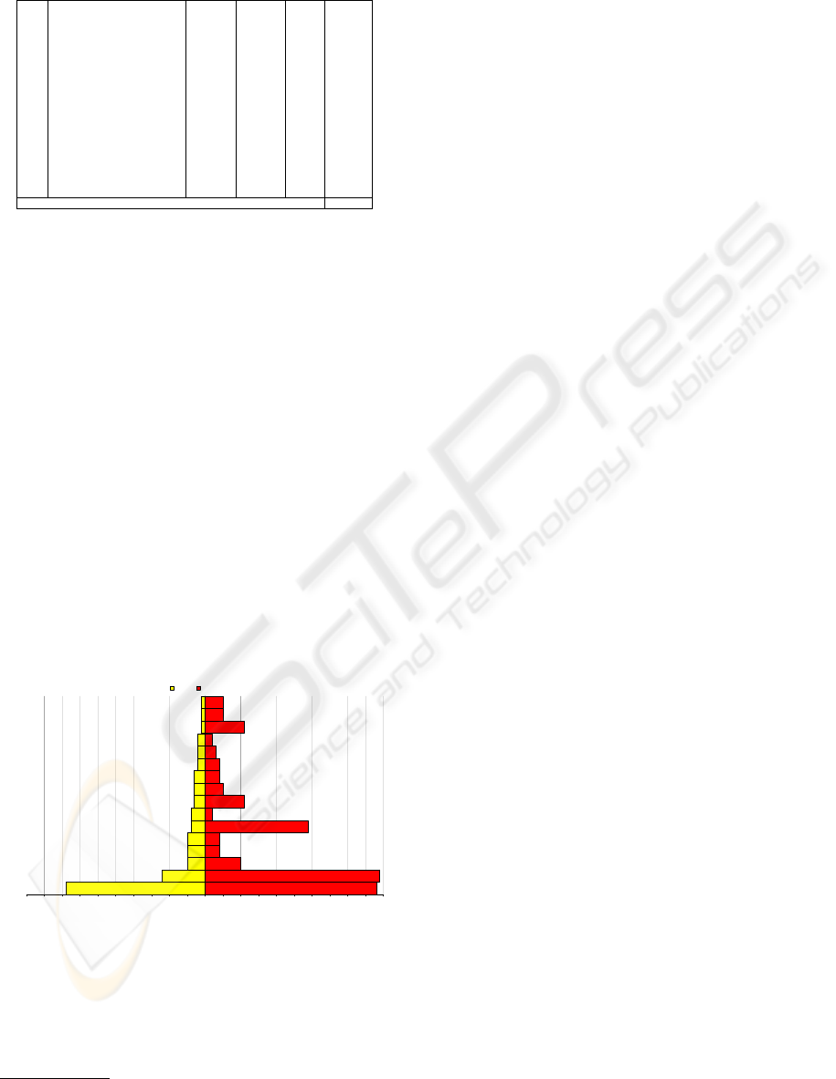
Table 1: Results.
# Use Case # UI # UI Abs. Rel.
UMLet R.Rose Diff. Diff.
1 Create a class 2 4 +2 100%
2 Extend class with attributes 5 4 -1 -20%
3 Extend class with one o peration 5 4 -1 -20%
4 Modify an attribute 5 10 +5 100%
5 Duplicate a class 1 11 +10 1000%
6 Add an aggregation 4 2 -2 -50%
7 Modify an aggregation 1 5 +4 400%
8 Change a generalization 1 5 +4 400%
9 Delete a class 2 3 +1 50%
10 Undo class delete 2 2 +/-0 0%
11 Simple class diagram 39 48 +9 23%
12 Simple sequence diagram 4 29 +25 625%
13 Change message direction 3 11 +8 266%
14 Change message type 3 5 +2 66%
15 Add a message 3 4 +1 33%
16 Create a sequence diagram 12 49 +37 308%
Median Relative Difference 83%
# UI = number of user interactions
Rose. To complete simple but frequent tasks when
creating UML sketches, users are required to perform
about 80% more interactions with Rational Rose than
UMLet.
1
Surprisingly, duplicating a class element (use case
5) in Rational Rose is an extremely cost intensive
task. It requires 11 interactions in Rose, and just one
in UMLet. Apart from use case 5, use case 16 shows
the maximum performance advantage of all tested use
cases. The reason is UMLet’s special grammar for se-
quence diagrams. It especially frees the user from the
task of placing and resizing the various sub-elements’
graphical representations. In order to keep the gram-
mar’s syntax simple, UMLet makes some trade-offs
and does not support the full functional range of the
UML sequence diagram. UMLet does provide sup-
port for creating such diagrams conventionally, using
individually placed elements. In this case, however,
UMLet’s advantage shrinks.
50 45 40 35 30 25 20 15 10 5 0 5 10 15 20 25 30 35 40 45 50
11
16
4
2
3
12
6
13
14
15
1
9
10
5
7
8
Use Case ID
User Interactions
UMLet Rational Rose
Figure 6: Results.
As documented in table 1, operations like chang-
ing the direction of dependencies (use case 8) or
changing the type of dependencies (use case 7) are
very simple using UMLet. Rational Rose’s way of
1
The sign test rejects the null hypothesis of a zero me-
dian difference; it is significant at the 5% level.
dealing with this is more time-consuming. In theory,
this seems to be o.k.—after all, a dependency’s direc-
tion or type seems to be so fundamental that changing
it does not make sense in most cases. We found, how-
ever, that these use cases actually occur quite often
when sketching diagrams, especially if the wrong re-
lation was inadvertently added to the diagram, if the
classes responsibilities change, or if inheritance struc-
tures are broken up and changed to looser class rela-
tions.
Although not covered by our test, even the simple
task of adding multiplicities can turn out to be a strug-
gle. Rational Rose offers two ways of adding multi-
plicities to a relation. Either the user selects it from
a list box in one of the tabs of the specification dia-
log (requiring 6 user interactions), or the user selects
the multiplicity type from the context menu (requir-
ing 3 user interactions). The problem is that the user
then often realizes that the multiplicity was added at
the wrong side of the relation. So he is often forced
to delete the multiplicity and re-add it. Mistakes like
these occur in UMLet, too, but the correction can be
done in a single user interaction using the text-based
attribute specification, whereas Rose requires the en-
tire process to be repeated.
The comparison of the two tools should not deter-
mine a “better” UML tool—after all, the tools have
widely different aims. UMLet, in this paper, should
merely denote a baseline, a low-complexity approach
to which Rational Rose, one of the leading UML
tools, can be compared with respect to fast UML
sketching. Our comparison indicates that Rational
Rose, on average, requires almost two times as many
user interactions as necessary.
Is this merely the consequence of the fact that Ra-
tional Rose has many more features, and has to en-
force more formal UML standards? Or, more gener-
ally, do tools dealing with complex demands neces-
sarily become more complex?
We don’t think so. A good example is Mi-
crosoft’s suite of integrated development environ-
ments, Visual Studio. While offering an astonish-
ing array of options and features, the basic func-
tionalities of programming—typing, searching, look-
ing up object members—continue to be very easy to
use. The search functionality was actually improved
over time (it is now non-modal, and offers a history
of searches) without sacrificing usability; the object
member lookup still hides complex functionality be-
hind an unobtrusive and efficient user interface.
Tools thus are able to both tackle complex require-
ments, and to provide intuitive base functionality. In
the quest to offer ever-more features, this goal should
not be neglected.
ICEIS 2007 - International Conference on Enterprise Information Systems
472

7 CONCLUSION AND FURTHER
RESEARCH
This paper compares two UML tools with respect to
their suitability for explorative UML sketching. Sev-
eral common UML design tasks were tested to deter-
mine the number of required user interactions.
The large, standard-conforming and -enforcing
Rational Rose was found to require substantially more
user interactions than UMLet. As Rational Rose’s de-
sign goals have to accommodate a wide range of re-
quirements, fast and explorative UML sketching be-
comes less intuitive and more tedious. This is as-
sessed by comparing Rational Rose to UMLet, a tool
specifically tailored to creating UML sketches.
We argue that as tools get more complex, develop-
ers must make sure to avoid compromising on impor-
tant base functionality—otherwise, a tool will cover
more requirements, but important ones less well.
Further research will focus on
• aspects of tool complexity and integration, espe-
cially on ways to integrate separate interactive and
highly graphical applications;
• refined user interaction measures, that take into
account not just the number of user interactions,
but their type and complexity (like decoding an
icon’s meaning, or clicking on small, scattered
buttons).
REFERENCES
Apple Computer Inc. (1992). Macintosh Human Interface
Guidelines (Apple Technical Library). Addison Wes-
ley, 2nd edition.
Auer, M., Meyer, L., and Biffl, S. (2007). An approach for
testing the usability of UML tools (TR TU:IFS:QSE
07-001). Technical report, Institute of Software Tech-
nology and Interactive Systems, University of Vienna.
Auer, M., Tschurtschenthaler, T., and Biffl, S. (2003). A fly-
weight UML modeling tool for software development
in heterogeneous environments. In Proceedings of the
29th Euromicro Conference (EUROMICRO’03), An-
talya.
Booch, G., Rumbaugh, J., and Jacobson, I. (2005). Uni-
fied Modeling Language User Guide, The. Addison
Wesley, 2nd edition.
Chen, Q., Grundy, J., and Hosking, J. (2003). An e-
whiteboard application to support early design-stage
sketching of UML diagrams. In Proceedings of the
2003 IEEE Symposium on Human Centric Computing
Languages and Environments (HCC’03), pages 219–
226, Auckland.
Dagdeviren, H., Juric, R., and Lees, P. (2004). Experi-
ences of teaching UML within the information sys-
tems curriculum. In Proceedings of the 26th Interna-
tional Conference on Information Technology Inter-
faces (ITI’04), volume 1, pages 381–386, Dubrovnik.
Eichelberger, H. (2002). Evaluation-report on the layout
facilities of UML tools. Technical report, Department
of Computer Science, University of W
¨
urzburg.
Evans, A. S. and Wellings, A. J. (1999). UML and the for-
mal development of safety-critical real-time systems.
In IEE Colloquium on Applicable Modelling, Verifica-
tion and Analysis Techniques for Real-Time Systems
(Ref. No. 1999/006), pages 2/1–2/4, London.
Fowler, M. (2003). UML Distilled: a brief guide to the
standard object modeling language. Addison Wesley,
3rd edition.
Kohler, H., Nickel, U., Niere, J., and A.Zundorf (2000). In-
tegrating UML diagrams for production control sys-
tems. In Proceedings of the 22nd International Con-
ference on Software Engineering (ICSE’00), pages
241–251, Limerick.
Lahtinen, S. and Peltonen, J. (2003). Enhancing usability of
UML case-tools with speech recognition. In Proceed-
ings of the 2003 IEEE Symposium on Human Centric
Computing Languages and Environments (HCC’03),
pages 227–235, Auckland.
Medvidovic, N., Egyed, A., and Rosenblum, D. S. (1999).
Round-trip software engineering using UML: From
architecture to design and back. In Proceedings of
the 2nd Workshop on Object-Oriented Reengineering
(WOOR’99), Toulouse.
Moran, T. P., Chiu, P., and van Melle, W. (1997). Pen-based
interaction techniques for organizing material on an
electronic whiteboard. In Proceedings of the 10th an-
nual ACM Symposium on User Interface Software and
Technology (UIST’97) , pages 105–114, Alberta.
Quan, D., Huynh, D., Karger, D., and Miller, R. (2003).
User interface continuations. In Proceedings of the
16th Symposium on User interface software and tech-
nology (UIST’03), pages 145–148, Vancouver.
Raskin, J. (2000). The Humane Interface: New Directions
for Designing Interactive Systems. Addison Wesley.
Rumbaugh, J., Jacobson, I., and Booch, G. (2004). The
Unified Modeling Language Reference Manual, Sec-
ond Edition, page 125. Addison Wesley.
Tenzer, J. (2004). Improving UML design tools by formal
games. In Proceedings of the 26th International Con-
ference on Software Engineering (ICSE’04), pages
75–77, Edinburgh.
The Object Man Group (2006). www.omg.org.
Tidwell, J. (2005). Designing Interfaces. O’Reilly Media.
Zhang, B. and sho Chen, Y. (2005). Enhancing UML con-
ceptual modeling through the use of virtual reality. In
Proceedings of the 38th International Conference on
System Sciences (HICSS’05), pages 11b–11b, Hawaii.
EXPLORATIVE UML MODELING - Comparing the Usability of UML Tools
473
